

Samsung CF21M Troubleshooting
5 Troubleshooting
5-1 Parts Level Troubleshooting
Notes: 1. If a picture does not appear, Click the Brightness and Contrast button on the front panel, and then increase the value
of Brightness and Contrast.
2. Check the following circuits.
• No raster appears: Power circuit, Horizontal output circuit, H/V control circuit, and H/V output circuit.
• High voltage develops but no raster appears: Video output circuits.
• High voltage does not develop: Horizontal output circuits.
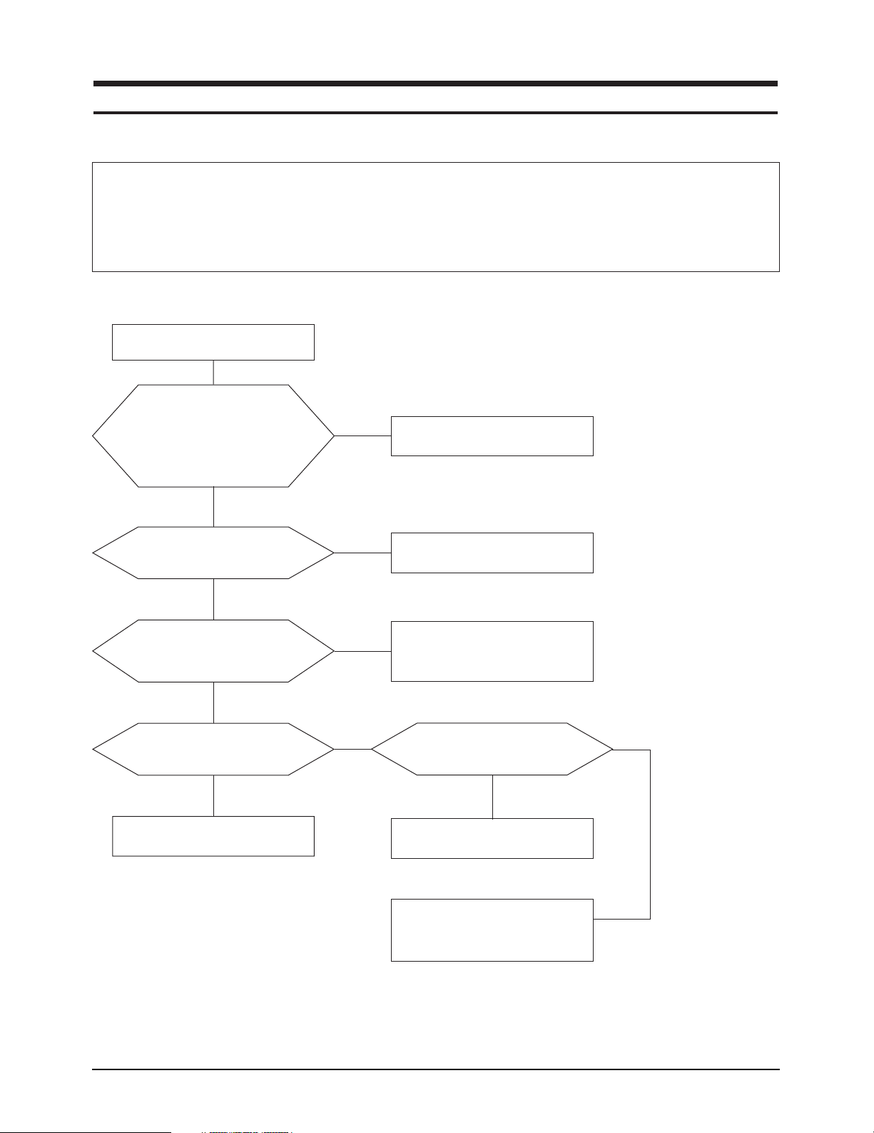
5-1-1 No Power Supply
Check and replace FG601, D601,
D701, Q701, IC601 and ZD601.
Check the Voltage at
C607 plus polarity point.
Is the Voltage 400VDC?
with PFC : 400VDC
without PFC : it is different
according to input voltage
Yes
No
Check and replace
FG601, D601, D703.
IC601 Pin 1 waveform is right?
Yes
The secondary voltage of
T601 is right?
(Is it same the schemetic diagram)
Yes
Check IC651 (KA78R12) Pin 12?
•
Is the voltage 12VDC?
•
Yes
Done.
No
No
No
Check and replace
IC601, ZD601, D606, IC701.
Check TR, IC and biode
related to every B+line.
Appear 4VDC Pin 4 of IC651?
No
Check and Micom. (IC201)
•
Check and replace IC651.
•
Check every IC connected to 12V.
Yes
CF21M* 5-1
5 Troubleshooting
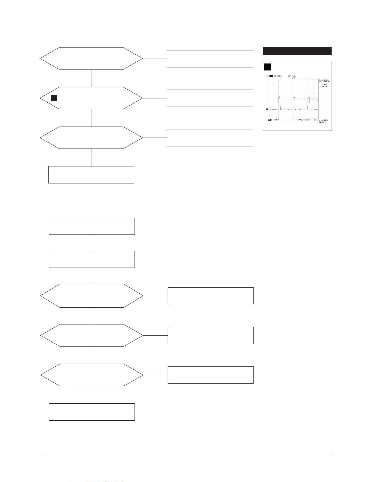
5-1-2 PFC Failure
Check the Voltage at IC701 Pin5.
The Voltage is around 10VDC?
Yes
1
Q701 Gate waveform is right?
Yes
Check the Voltage at D701 cathode.
The Voltage is about 400VDC?
Yes
Done.
5-1-3 DPMS Failure
Check signal source
H/V sync. video signal.
No
No
No
Check and Replace D702,
R711, ZD705, ZD706.
Replace IC701.
Replace Q701, D701.
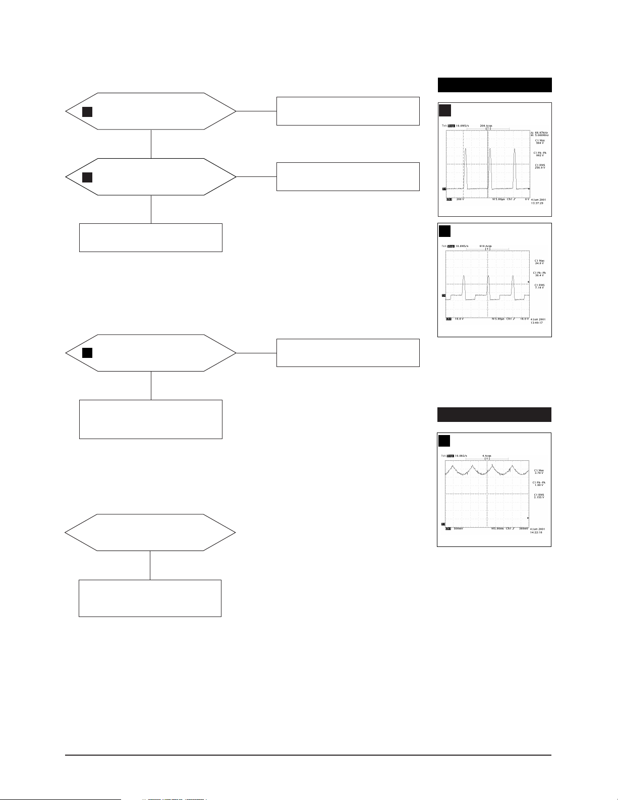
WAVEFORMS
368 V (IC601, #1)
1
Make No H/V sync.
( That is power off mode).
LED blinks?
Does +12V Line off?
(Check the IC651 output Pin 2)
Yes
Does +14V_V Line off?
(Check the Q670 Collector)
Yes
Does the Q620 activate?
Yes
Done.
No
No
No
Check IC201 Pin 25
or replace IC201.
Check Q671, D670.
Check IC201 Pin 23
or replace IC201.
5-2 CF21M*
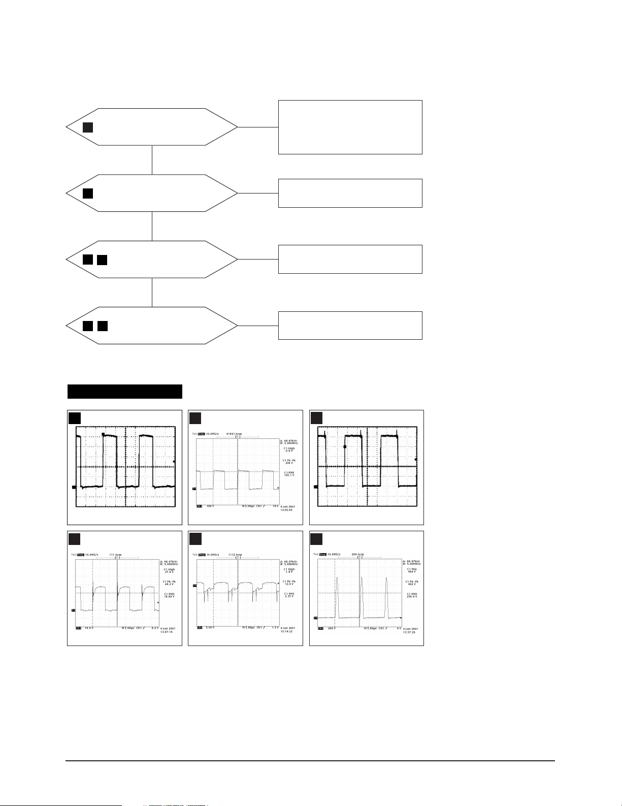
5-1-4 H_Deflection Failure
5 Troubleshooting
IC402 Pin 6 waveform is right?
2
Yes
3
Q454 drain
waveform is right?
Yes
4
Q401 gate, drain
5
waveforms are right?
Yes
Q402 base, collector
6
7
waveforms are right?
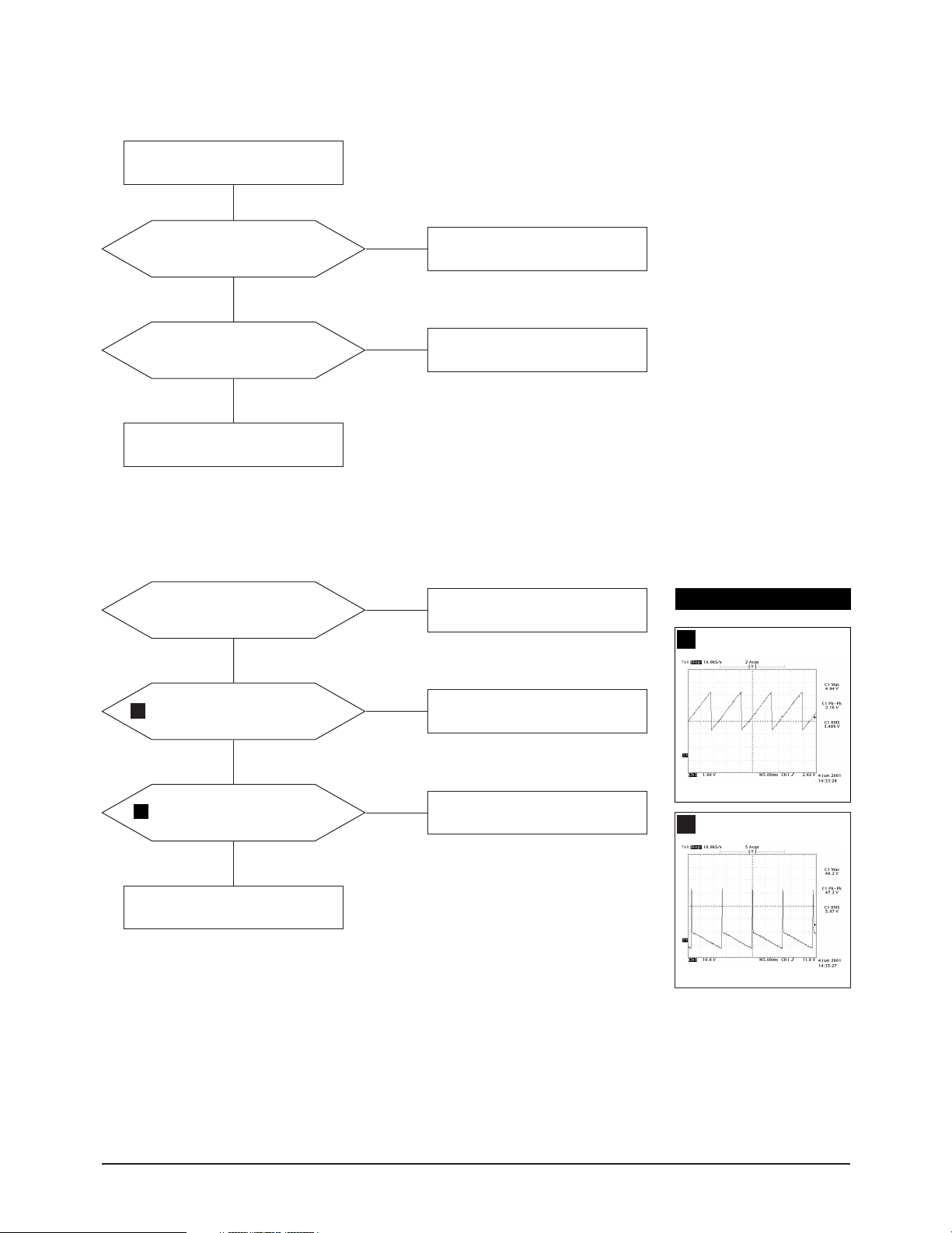
WAVEFORMS
No
No
No
No
1. Appear the Voltage 12VDCat
IC402 Pin 7 replace R451.
2. Check IC402 Pins 6~5, 7~6.
3. Replace IC402.
Check Q451, Q452, Q453,
ZD450, R467, D456.
Check Q250, Q251, IC250
Check +19V line.
Check and replace D402 and Q402.
Check DY connector connection.
IC402, #6
2
CH1 P-P = 10.96 V CH1 RMS = 6.180 V
Q401, Drain
5
Q454, Drain
3
Q402, Base
6
Q401, Gate
4
CH1 P-P = 11.6 V CH1 RMS = 6.944V
Q402, Collector
7
CF21M* 5-3
5 Troubleshooting
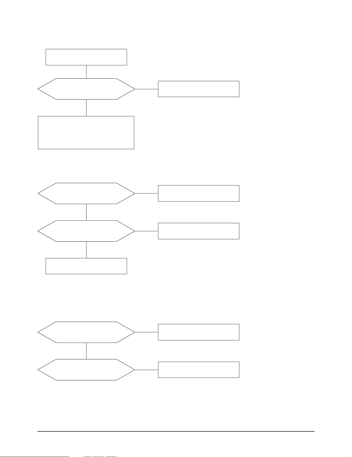
5-1-5 S Correction Failure
Check S1 ~ S5 signal.
Refer to the S-corrction table page?
S1~S5 signals are right at
each frequency block?
Yes
Check and replace
C411, C413, C414, C415, C416,
C417, C418, Q403 ~ Q407, Q408 ~ Q412
5-1-6 H_Lin. Failure
IC201 Pin 3 voltage varies with
different H_Lin. DAC values?
Yes
IC403 Pin 7, 8 voltage varies with
different H_Lin. DAC values?
Yes
No
No
No
Check and replace IC201.
Replace IC201.
Check +12 V line.
Check some parts around IC403.
Check L403.
5-1-7 Invariable H_Size
D250 Cothode voltage varies with
different H_Size DAC values?
Yes
IC402 Pin 6 output duty varies with
different H_Size DAC values?
No
No
Check and replace IC250, IC201.
Check some parts
around IC250, IC201.
5-4 CF21M*
5-1-8 Abnormal H_Size
5 Troubleshooting
WAVEFORMS
The Voltage waveforms at
7
Q402 Collector are right?
Yes
T402 pin 8 wareform is right?
8
Yes
Check some parts around
IC250 and IC402 Pin 1 and 2.
5-1-9 Side Pin or Trap Failure
IC250 Pin 24 output exists?
9
The waveform is right?
Yes
No
No
No
Repeat the troubleshooting
Guide of H_deflection failure.
Replace T402.
Check and replace IC250.
Q402, Collector
7
T402, #8
8
Check and replace IC402.
Check some parts IC402 Pin 2
and IC250 Pin 24.
5-1-10 Para. or Pin Balance Failure
IC250 Pin 24 output varies with
different DAC values?
No
Replace IC261.
WAVEFORMS
IC250, #24
9
CF21M* 5-5
5 Troubleshooting
5-1-11 Tilt Failure
Check tilt connector connection
IC201 Pin 5 output duty varies
with different DAC values?
Yes
IC403 Pin 10, 11 output varies with
different DAC values?
Yes
Check and replace CRT.
5-1-12 V Deflection Failure
Is 14V at IC301 Pin 2?
Is -14V at IS301 Pin 5?
Yes
No
No
No
Check and replace IC201.
Check and replace IC403.
Check and replace R312, R316.
Refer to 5-1-1 No Power supply.
WAVEFORMS
IC250, #23
10
IC250 Pin 23 output exists?
10
The waveform is right?
Yes
IC301 Pin 6 output exists?
11
The waveform is right?
Yes
Check V DY connector connection.
No
No
Check and replace IC250.
Check and replace some
parts around IC301.
IC301, #6
11
5-6 CF21M*
 Loading...