

Page 1

7-1-1. Overview
7-1-2. Operation
1. If the weight of the food is less than 1.5Kg (including the cooker), the rotating dish automatically
moves to the optimum location by the elevation motor.
(If the weight is more than 1.5Kg the cooking is done in the basic location)
2. When defrosting, the weight sensor detects the weight and moves the food to the appropriate
height . (The elevation operates when the weight is less thon1.0Kg or less (including the dish)).
3. When reheating food 700g or less (including the dish), it swings once and then cookis in the basic
location. (If the weight is 700g the cooking is done in the basic location)
4. Manual cooking is done in the basic location with only the rotating motor operating.
(Maximum of 4Kg including the dish if the weight exceeds 4kg, an ÒE5Ó error occurs.)
7-1-3. Operating Principle of the Height Sensor
The weight sensor converts the weight of the food into a series of pulses that are compared to
the"zero point" wavefrom. This frequency difference determines the cooking time.
7. Troubleshooting
7-1Samsung Electronics
7-1 Checking the Weight Sensor
Tantable motor
Elevarion motor
( Output Wave )
The output frequency of the basic condition (when 0
point adjusted) is between 3150 and 3650Hz.
5V
0V
Shaft
Weight sensor
Page 2
Samsung Electronics7-2
Troubleshooting
7-1-4. Zero point and Inclination Adjustment
1. Turn the power on again and set time initial condition to Ò8888Ó.
2. Put a dish inside the cooking space.
3. Press the sensor defrost( ) and power level/more,less( ) keys simultaneously until Ò0000Óis
displayed (about 5 seconds).At this time lamp and the rotating dish motor are on.
4. After 10 seconds, A normal neading is between 3150 and 3650.
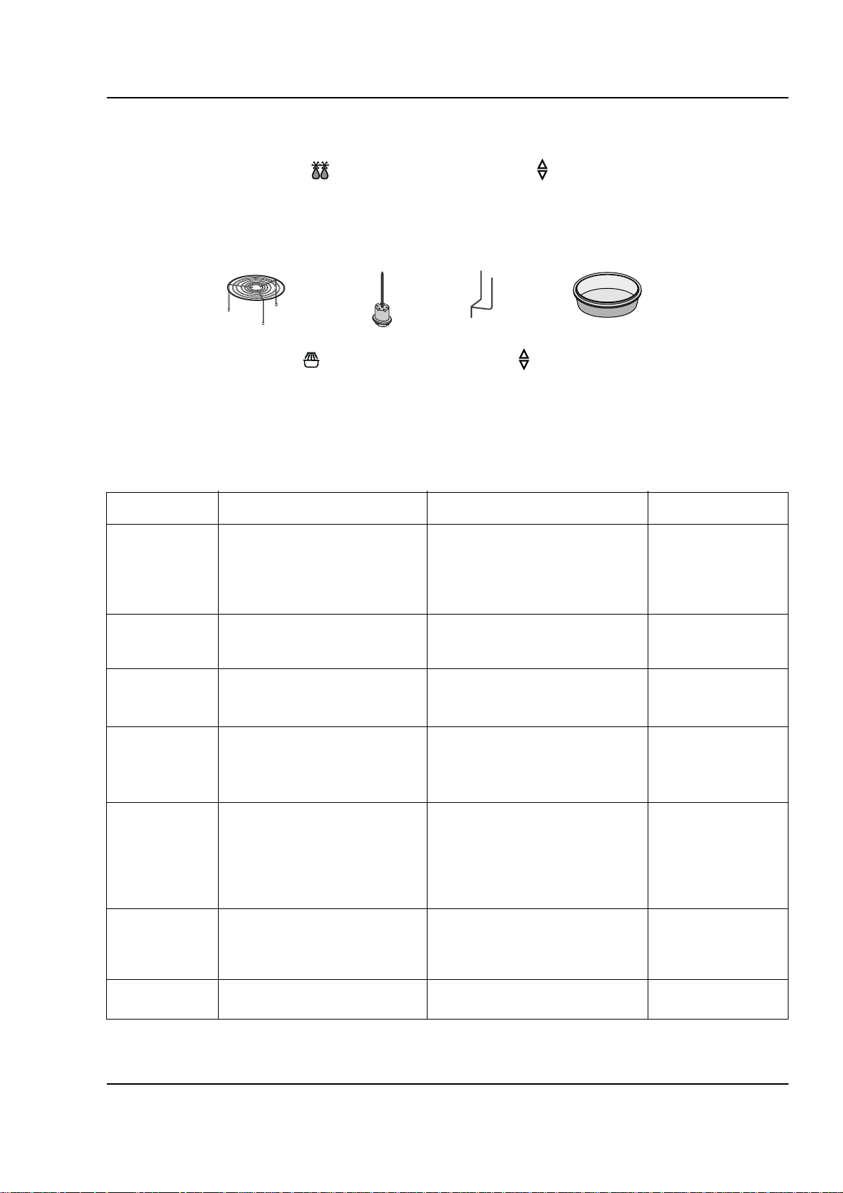
5. Put the 1Kg standard weight at the center of the glass tray and close the door.
(When setting the 1Kg weight, put the metal rack, roasting spit, glass bowl and two skewers on the
glass tray. Then do the zero point adjustement.)
6. Press the sensor reheat( ) and power level/more,less( ) keys simultaneovsly until the Ò1111Óis
displayed. (about 5 seconds). At this time lamp and the rotating dish motor are on.
7. After 10 seconds, A normal reading is between 0350 and 0650.
8. Press the cancel key to complete the adjustment.
7-1-5. Error codes
(Metal Rack)
(roasting spitspit) (two skewers) (glass bowl)
Error indication Cause of occurrence Management method Remarks
E0 Gas sensor open/short Check the connection and Automatic
(sensor value cooking reheating reheating
between 6 and 211) Put the power switch again and
and use it after 10 minutes.
E1 Exceeds of T1 time limit First press the cancel key and Automatic
(gas sensor) check if the food is positiotes reheating
E4 Problem with the weight Exchange the weight sensor
sensor (Output frequency=0Hz) Check the wire connection
E5 Excess of maximum weight Cook within 4Kg
(The total weight exceeded
4Kg)
E6 Excess of maximum allowed When cooking 300g or less,
time with maximum load cook within 10minutes.
(When cooking food that
weight less tman 300g the
maximum time is 10 minutes.)
E8 No tray (Occurs if oven is Install the rotating dish
operated without the rotating
dish.)
E10 Problen with the EEPROM Replace the PCB assy
Page 3

Samsung Electronics 7-3
Troubleshooting
7-1-6. Hidden key
1. Check the gas sensor : Press the sensor defrost and sensor reheat keys simultaneovsly.
(Display : Between 5 and 210).
2. Child lock function : Press the cancel key for 3 seconds
(the function is executed after the buzzer sounds). To ondo the child lock,
press the cancel key for 3 seconds.
3. Cooking completion remind function : If the food is not removed after cooking,
the buzzer sounds every minute.
7-1-7. Precautions
1. Do not apply heavy load or pressure on the rotating dish
(The elevation and the weight sensor directly contact the rotating dish).
Putting food that exceeds 4kg(Total) can damage the weight sensor.
2. Use only genuine replacements that fit the model(C.E., rotating dish and supporter).
3. When food exceeding 300g(Total) is put on the rotating dish, the oven operates for only 10 minutes.
(Error E6 occwrs.)
7-1-8. Reppacing Parts
1. Discharge the capacitor for about 5 to 6 minutes after cutting the power, and then continue the work.
2. Do not damage the coating on the wires.
3. When removing the wire the terminal, hold the positive lock case with the finger and assemble it.
Otherwise use a tool (such as long nose pliers)
4. If you remove the tie during servicing, do not damage the wire. Adjust and arrange the wire and
tie(heat proof onsulated tie) after the repairs have been completed.
Page 4

Samsung Electronics7-4
Troubleshooting
7-2 Simple Troubleshooting Chart
PRECAUTION
1. FIRST CHECK THE GROUND CONNECTIONS.
2. BE CAREFUL OF THE HIGH VOLTAGE CIRCUIT.
3. DISCHARGE THE HIGH VOLTAGE CAPACITOR.
4. WHEN CHECKING THE CONTINUITY OF THE SWITCHES OR TRANSFORMER, DISCONNECT ONE LEAD WIRE FROM THESE
PARTS AND THEN CHECK CONTINUITY WITHOUT THE POWER SOURCE ON. OTHERWISE YOU MIGHT DAMAGE THE METER
ORGET APTISE READING.
5. DO NOT TOUCH ANY PART OF THE CIRCUIT OR THE CONTROL CIRCUIT BOARD, SINCE STATIC DISCHARGE MAY DAMAGE IT.
ALWAYS TOUCH GROUND WHILE WORKING ON IT TO DISCHARGE ANY STATIC CHARGE BUILT UP.
Item Checking Procedwre
Inspection of a. Put about 200cc of tap water (water temperature 10-18°) on
microwave oven cooking the rotating dish.
b. Do the following :.
Microwave oven high ¡ time setting 5 minute ¡ start cooking
c. The water temperature should be about 80°
Inspection of grill cooking a. Put the applicable " cooker" for grill cooking inside
b. Do the following grill ¡ time setting
5 minutes ¡ start cooking.
c. Normal : The seize heater is red.
Page 5

Samsung Electronics 7-5
Troubleshooting
7-3 Problem Analysis
7-3-1 When inserting the power plug (function selection, door on/off)
7-3-2 When operating
Problem location Cause Measures
No alphivumeric a. Fuse (250V, 10A) Open bad contacts Exchange
display b. Magnetron and case, Exchange
temperature switch
c. Power plug and socket Bad contacts Exchange,repair
d. 1st and 2nd of LVT Cut-off Exchange
e. Connector of PCB board Bad insertion Repair
f. Highlight indication plate Poor Exchange
g. Circuit within the PCB board Board DC fect on PC Board exchange
Fuse is damaged a. Power transformer Short circuit Exchange
(short circuit) b. Safety switch Fusion and poor Exchange
c. Monitor switch (short switch) Poor operation Latch adjustment
d. HVC Short circuit Exchange
e. Latch operation Poor operation Latch adjustment
Problem location Cause Measures
Electrical a. Grounding wire Bad grounding Inspection
shock b. AC 230V power line is Lead wire not connected
the chassis Exposed part of the power Adjustment
line is shorting the
chassis
Lamp is not on a. Lamp and lead wire Disconnected Exchange/adjustment
b. Check the lamp relay Coil disconnected Exchange
c. Thermostat 2EA Bad contact point Exchange
d. LVTransformer Is the LVT wire normal? Exchange/adjustment
Elevation a.Check the connections to Poor wire connection Adjustment
action the elevation assembly
unsatisfactor b. Continuity between terminals Disconnection Exchange/
of the elevation motor Assembly exchange
(Measure after removing
the power leads)
Page 6

Samsung Electronics7-6
Troubleshooting
7-3-2 When operating (Continued)
Problem Inspecting location Cause Measures
Fuse blows out a. Resistance between high voltage The nesistmce should be . Exchange
condenser terminals about 10§
(Measure it after cutting the
power and pulling the terminal)
b. High voltage transformer Fuse is blown if
(See precautions) secondary winding is
open
c. High voltage transformer Resistance neadings
(Cut the power) should be:
A=about 96§
B=about 0.1§
C=about 1.6§
D=¡˜
but ween c
Sparks occvr durins a. Quality of the "cooker" Misuse of metallic Explanation
cooking being used material Explanation /
b. Left-over food Carbonization of food and cleaning
left over Explanation/
c. Piacement of the bupporter Poor placement of and adjustment
rotating shaft
Microwdve leakage a. Condition of the door Assembly Not enough contact Adjust the door
puring operation b. The surface contacting the in the front side of the hinge .
front of the cooking room and cooking room and the Check the operating
the door door condition of the
Deformation safety switch.
Adjustment
or exchange
Food does a. Continuity between Disconnection Exchange
not heat magnetron terminals
b. High voltage transformer 1st coil Disconnection
continuity (Measure it after cutting
the power lead).
c. Continuity of high voltage diode Forward direction
(Measure it after cutting the =about 0§
power leads).
d. Continuity between the magnetron Reverse direction =500§
e. High frequency emissions Bad continuity
Bad magnetron
f. Power relay operation Bad contact points
Page 7

Samsung Electronics 7-7
Troubleshooting
7-3-2 When operating (Continued)
Problem Inspecting location Cause Measures
Turntable a. Continuity between terminals Disconnection Exchange
motor doesn’t (Measure after removing the Adjustment
rotate power leads)
b. Lead (terminal) Needs cleaning Adjustment
c. Alien substance in
the motor
Fan motor a. Continuity between terminals Disconnection Exchange
doesn’t rotate (Measure after disconnecting the Poor insertion and Adjustment
power and lead wire) disconnection
b. Lead (terminal) Bad contacts needs Adjustment
c. Rotate the fan by hand cleaning or exchange
Poor defrosting a. Check the connections to Poor connection Adjustment
the weight sensor
b. Readjust the 0 point 0 point not adjusted Taking measures
according to
the error list.
Page 8

Samsung Electronics7-8
Troubleshooting
7-4 After-Repair Check Listd
No Check item Checking and judging method Remarks
1 Insulation resistance When measuring the insulation resistance between DC 500V Megatester
the power plug and the grounding wire(with the
power plug disconnected from the socket and the
door closed) the resistance should be greater than
1§ or above. When to check :
a. When the electric field parts are exchanged
b. If the MWO is used in a very humid envir qwment
c. Unit is older than 5 years
2 Safety switch Check that the safety switch is Safety switch
operation operating correctly when opening and Monitor switch
closing the door Door detection switch
3 Applicability of parts Check that exact replacement parts are being used AC 230V
4 Placement of Check for looseness, jamming or terminal insertion
lead wire of the lead wire. (check that there are no shorts to
ground.
5 Connection of Check the connection between he screw and bolt.
screw and bolt
6 Alien substance Check for a cut line within the equipment,
insertion check combustible foreign matter, or loose hardware.
7 Power cord check Check that there is no damage to the cord, plug,
socket etc.
Also check that power rating is adequate.
8 Grounding check Check that the main body is grounded to the For the PCB ground
PCB. wire and power cord
ground wire,
Explain to the customer that he following are Check the continuity
dancerous hazards : to ground.
a. Connection to the gas pipe
b. Connection to the vinyl water pipe
c. Connection to the telephone line.
 Loading...