

Samsung CA17-19IS Disassemble
3-1-1 Before making Disassembly
1. Disconnect or power cord from the monitor.
2. With a pad beneath it, stand the monitor on its
front with the screen facing downward and
the base close to you.
3-1-2 Cabinet Disassembly
1. Remove the Stand from the monitor.
(Refer to Stand manual)
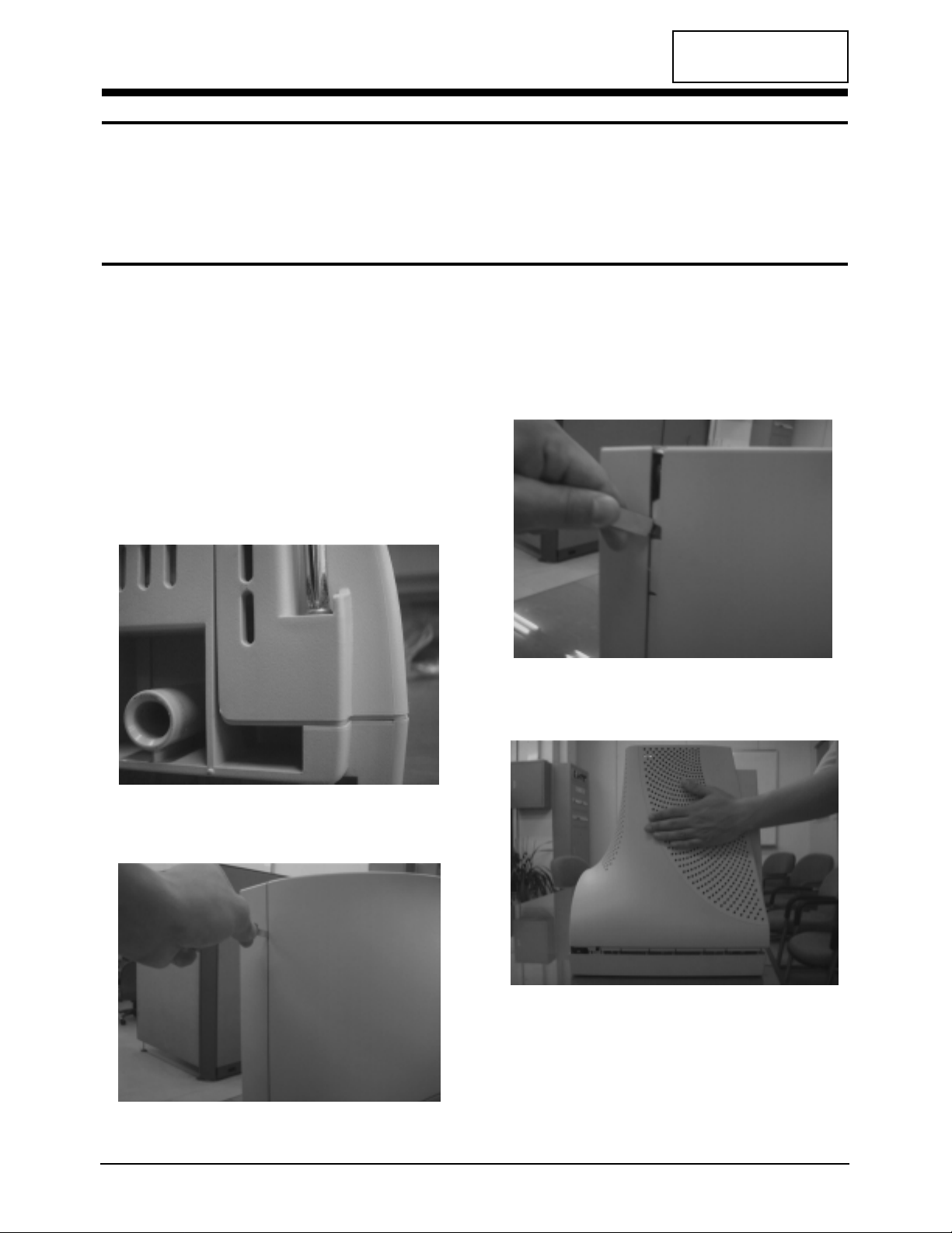
2. Remove 2 screws on the Rear cover.
3. Incline the monitor by lifting the rear of the
monitor.
4. Push the Opening jig each groove along the
Side of the monitor till it makes a “ttak”
sound. (2 grooves : Left and Right, Make sure
each snap is disengaged.)
5. Pull the Rear Cover up off the monitor.
CA17I*/CA19I* 3-1
CONFIDENTIAL
3 Disassembly and Reassembly
This section of the service manual describes the disassembly and reassembly procedures for the
CA17I*/CA19I* monitor.
WARNING: This monitor contains electrostatically sensitive devices. Use with caution when
handling these components.
3-1 Disassembly
Cautions: 1. Disconnect the monitor from the power source before disassembly.
2. To remove the Rear Cover, you must use the special opening jig tool.
Figure 1
Figure 2
Figure 3
Figure 4
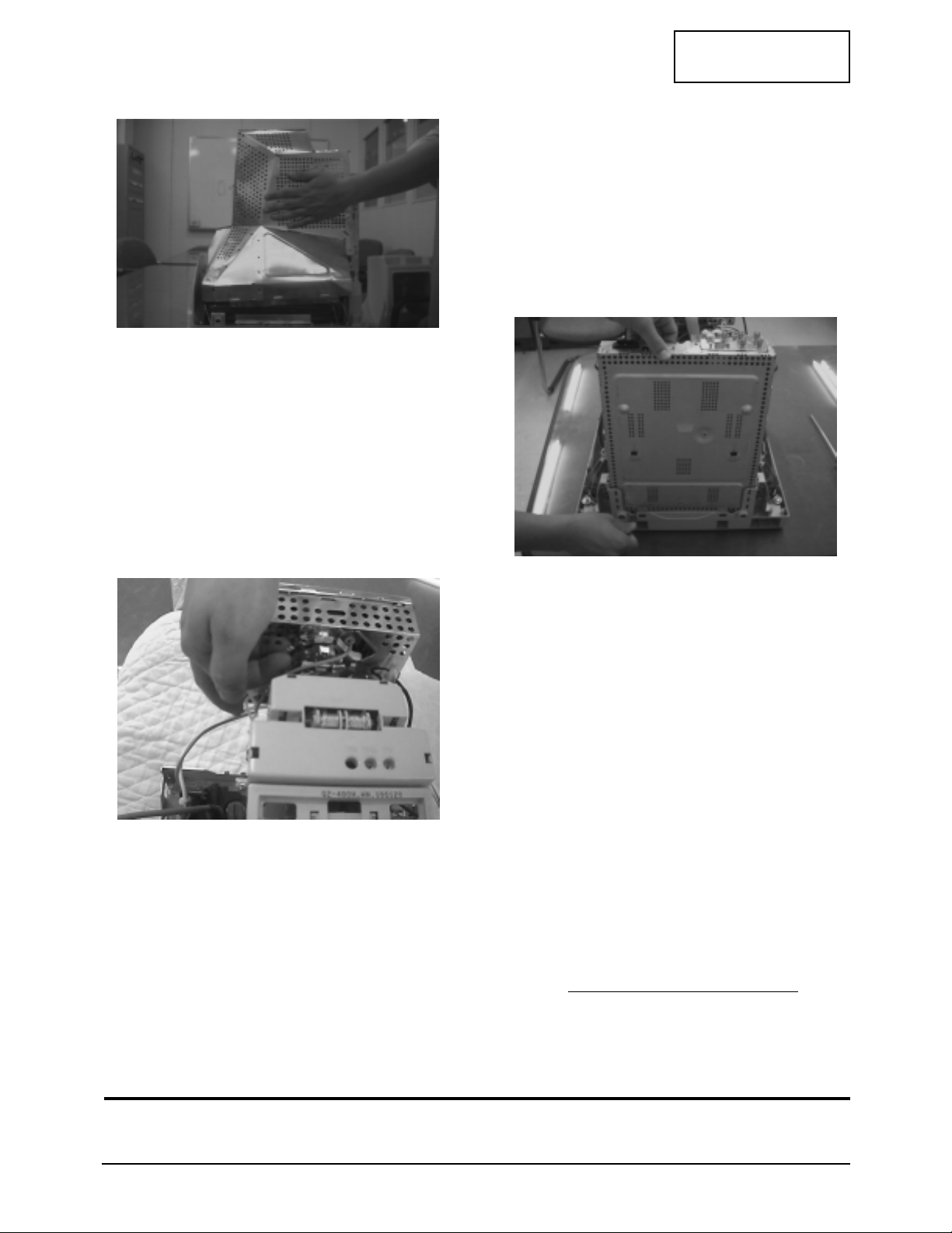
6. Remove the Shield.(TCO 99)
7. Using pinch-nose pliers or ling-nose pliers,
acrefully disconnect the Anode Cap from the
CRT.
Warning: Do not touch the Anode contact
on the CRT (High Voltage may
remain).
3-1-3 Removing the CRT Socket PCB
1. Complete all previous steps.
2. Lift up the Video Spring and remove the CRT
Socket PCB from the CRT.
3. Disconnect all connectors on the CRT Socket
PCB.
4. Using a solder iron, disconnect 5points
Ground (GND) on the back of the Video
Shield and remove the Shield Cap.
5. Remove the screw on the front of the Shield
Socket.
6. Place the Video PCB on a flat, level surface
that is protected from static electricity.
3-1-4 Removing the Main PCB
1. Complete all previous steps.
2. Disconnect the Degaussing Coil at CN601 on
the Main PCB.
3. Disconnect all easily accessible ground wires
on the PCB and Bottom Chassis.
4. Disconnect the DY connector at the CN401
connector on the Main .
5. Using the jig, release the snaps (2) connecting
the Front Cover and the PCB then lift up the
Bottom to separate the two Shield.
6. Disconnect the Tilt connector at the CN409
connector on the Main PCB.
7. Disconnect the Sub PCB connector at the
CN204 connector on the Main PCB.
8. Remove the screws on the back and along
each side of the Bottom Chassis.
9. Carefully lift the Main PCB Ass’y and remove
the remaining ground wires.
10. Place the Main PCB Ass’y on a flat, level
surface that is protected from static electricity.
3-1-5 CRT Ass’y Disassembly
1. Complete all previous steps.
2. Straighten the Degaussing Coil Assembly
coated metal ties and lift the Coil Ass’y from
the CRT.
3. Remove the four corner screws and lift the
CRT up and away from the Front Cover
Assembly and place it on a padded surface.
Caution: Do not lift the CRT by the neck.
If you will be returning this CRT to
the monitor, be sure to place the CRT
face downward on a protective pad.
3 Disassembly and Reassembly
3-2 CA17I*/CA19I*
CONFIDENTIAL
3-2 Reassembly
Reassembly procedures are in the reverse order of Disassembly procedures.
Figure 6
Figure 7
Figure 5
 Loading...