

Page 1
Level
8.
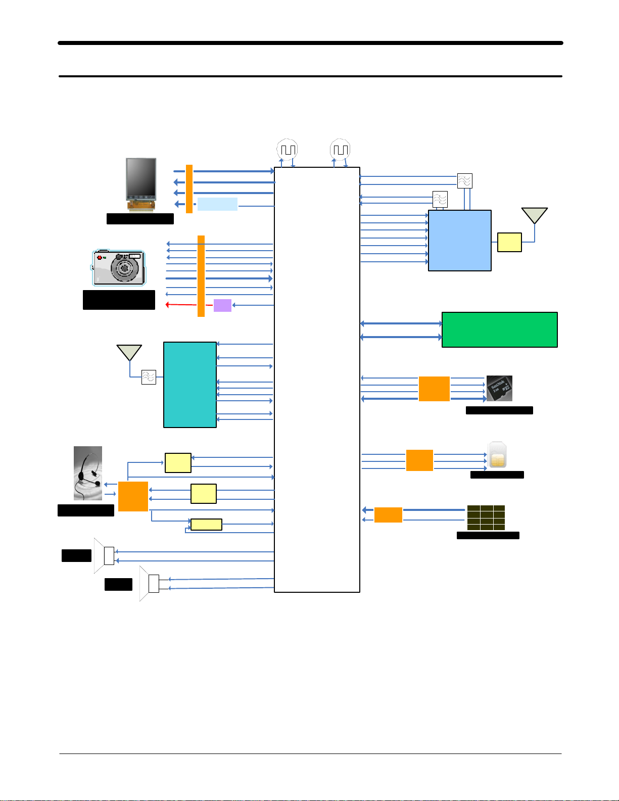
Block Diagram
8-1.
Repair
3
LCD Module
3 ME GA
CAM Module
BT ANT
SAW
LCD_CON
BT
BC63B239A04
FLM,LCD_RST
LCD _RS,C S,W R,R D
LCD _D(0:7)
BA CKLI GHT
DRIVER
CAM_DATA(0:7)
CAM _PC LK_IN
CA M _ C O N
CAM_M CLK_OUT
CAM
LDO
CLK26M_BT
BT_ REQ _CL K
PCM _S YNC
PCM _RX D
UART2_TXD
UART2_RXD
EN_LC D_B L
CAM_SCL
CAM _SD A
CAM_RS T
CAM_HSYN C
CAM_VSYNC
EN _C AM_PW R
BT _RST
PCM_C LK
PCM_T XD
26MHz
TCXO
RTC
Base Band
Catfish213
PMB8810
32.736KHz
DCS1800_RX
PC S1 9 00_ R X
GSM850_R X
GSM9 00_RX
DETECT _SD
SD_CMD
SD_C LK
SD_D ATA (0:3)
BS1
BS2
TX_EN
VL OGI C
RAMP
LB _T X
HB_TX
AD( 0:1 5 )
A(16:26)
SAW
SAW
2G PAM
SWITCH
Module
RF7161
256 NOR/1G On e N a n d /256 UtRAM
T-F LA SH
Socket
MEMORY
KAP 202N00 M-B WEW
T-FLA SH Card
Main ANT
RF
SW
EAR PHONE
SPK
FM_ANT_EAR
3.5pi
Socket
RCV
FM
LNA
EAR _3.5_L
EAR _3.5_R
EAR _MIC_P
SE N D_ EN D
FM_LNA_SW
FM_LNA_OUT
3.5_ CON_D ETE CT
EA R
AMP
COMP
EA R _ S PK _ L
EAR_SPK_R
EAR _SW
SEN D_END_DIREC T
SPK _P
SP K_N
RCV_N
RCV_P
SI M_R ST
SIM_C LK
SI M _I O
MAINKEY
CON
SI M
So ck et
KEY_COL(0:4)
KEY_ROW(0:4)
ONKEY_N
SI M Card
1 2 3
4 5 6
7 8 9
* 0 #
Main Key
8-1
SAMSUNG Proprietary-Contents may change without notice
This Document can not be used without Samsung's authorization
Page 2
Level3Repair
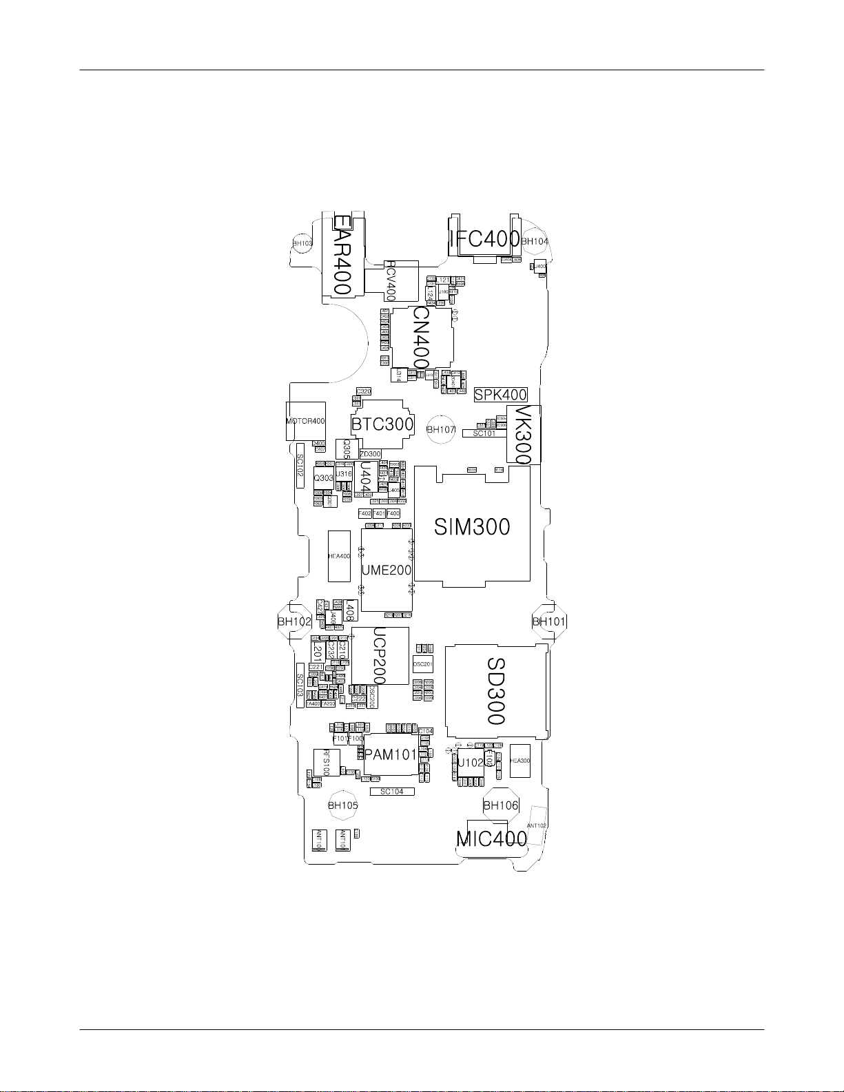
PCB Diagrams
8-2.
8-2-1.
Top
8-2
SAMSUNG Proprietary-Contents may change without notice
This Document can not be used without Samsung's authorization
Page 3
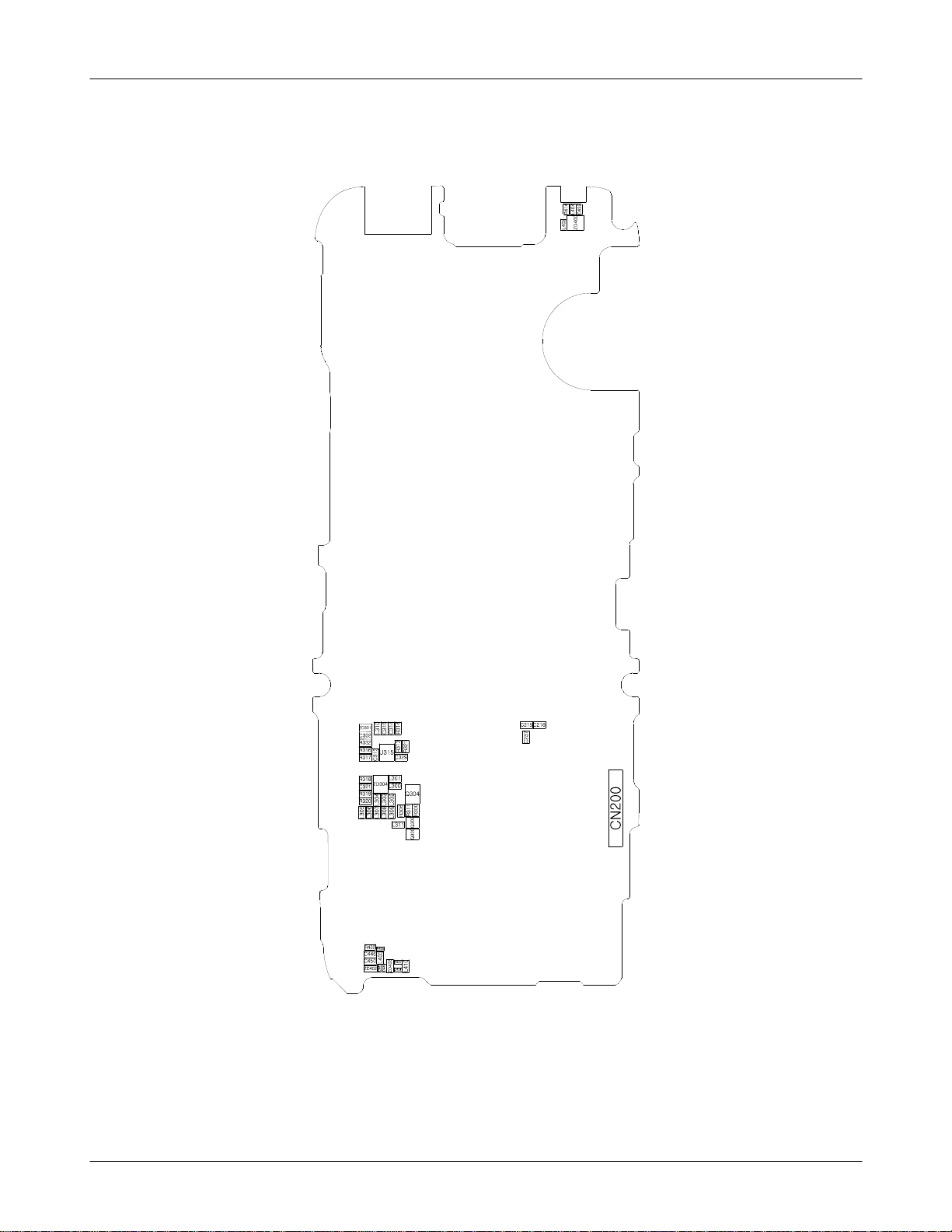
Level3Repair
8-2-1.
Bottom
8-3
SAMSUNG Proprietary-Contents may change without notice
This Document can not be used without Samsung's authorization
Page 4
Level3Repair
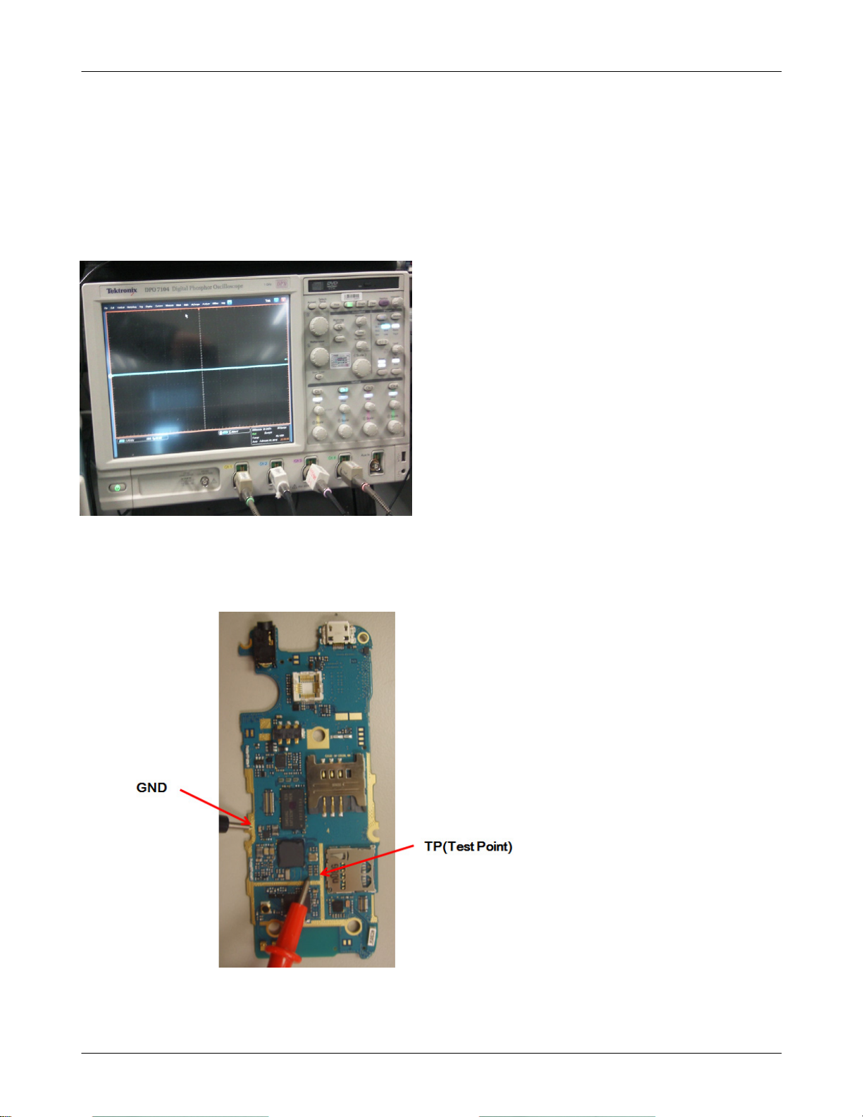
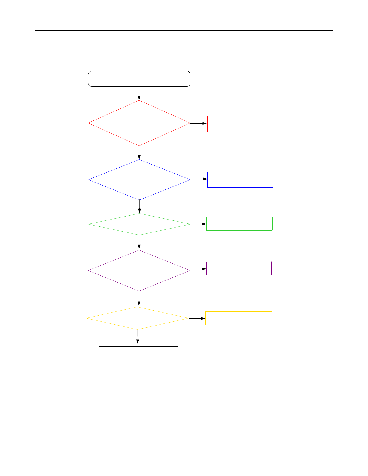
Flow Chart of Troubleshooting
8-3.
presetting methods for checking TP
(
GND&TP(exp. VBAT=
-
look over the coming out signal.
-
C210, C210,
C320
using Oscilloscope
)
Oscilloscope
8-4
SAMSUNG Proprietary-Contents may change without notice
This Document can not be used without Samsung's authorization
Page 5
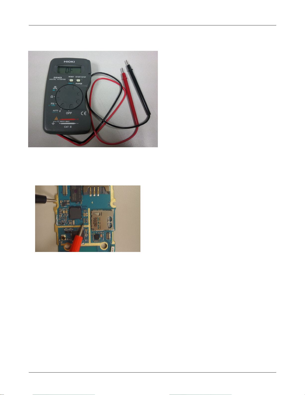
Multi-meter
Level3Repair
EX) to look up the TP, shunt Cap.
-
SAMSUNG Proprietary-Contents may change without notice
This Document can not be used without Samsung's authorization
Checking the TP(test point) using Multi-meter
if checking the GND, you can listen"beep"
-
if checking the Signal, you can't listen it.
8-5
Page 6
Level3Repair
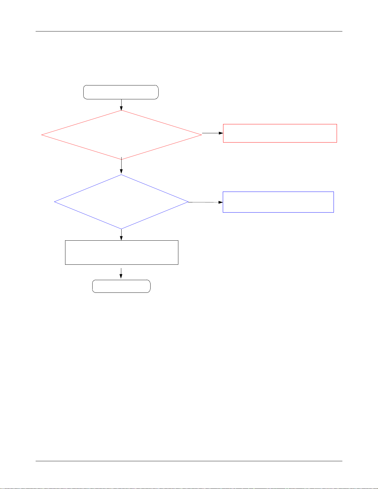
8-3-1.
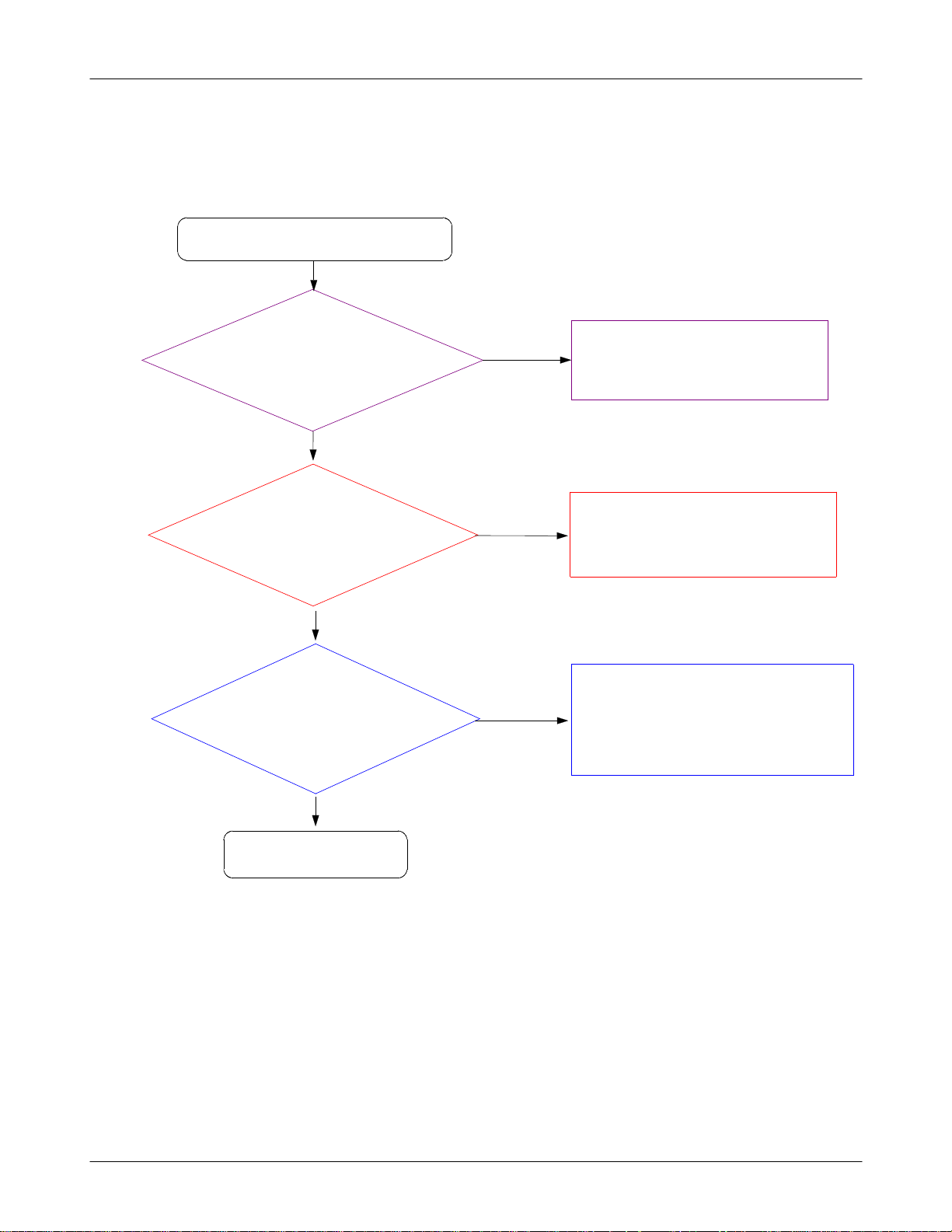
Power On
Power On'does not work
'
Check the Battery Voltage
is more than
TP:C
(
210 C220, C320)
VDD_1.8V
(
Check the Clock at
UCP200 A11pin
CLK26M)
(
TP:OSC201
(
Yes
Yes
=1.8
TP: C232)
Yes
=26M
3.7V
1,3
V?
HZ
pin
No
No
No
)
Change the Battery
Because of low batt. power)
(
Check the UCP200 is demaged.
Change the OSC201.
Yes
Check the UCP200 is demaged.
Yes
END
8-6
SAMSUNG Proprietary-Contents may change without notice
This Document can not be used without Samsung's authorization
Page 7
Level3Repair
8-7
SAMSUNG Proprietary-Contents may change without notice
This Document can not be used without Samsung's authorization
Page 8
Level3Repair
8-8
SAMSUNG Proprietary-Contents may change without notice
This Document can not be used without Samsung's authorization
Page 9
Level3Repair
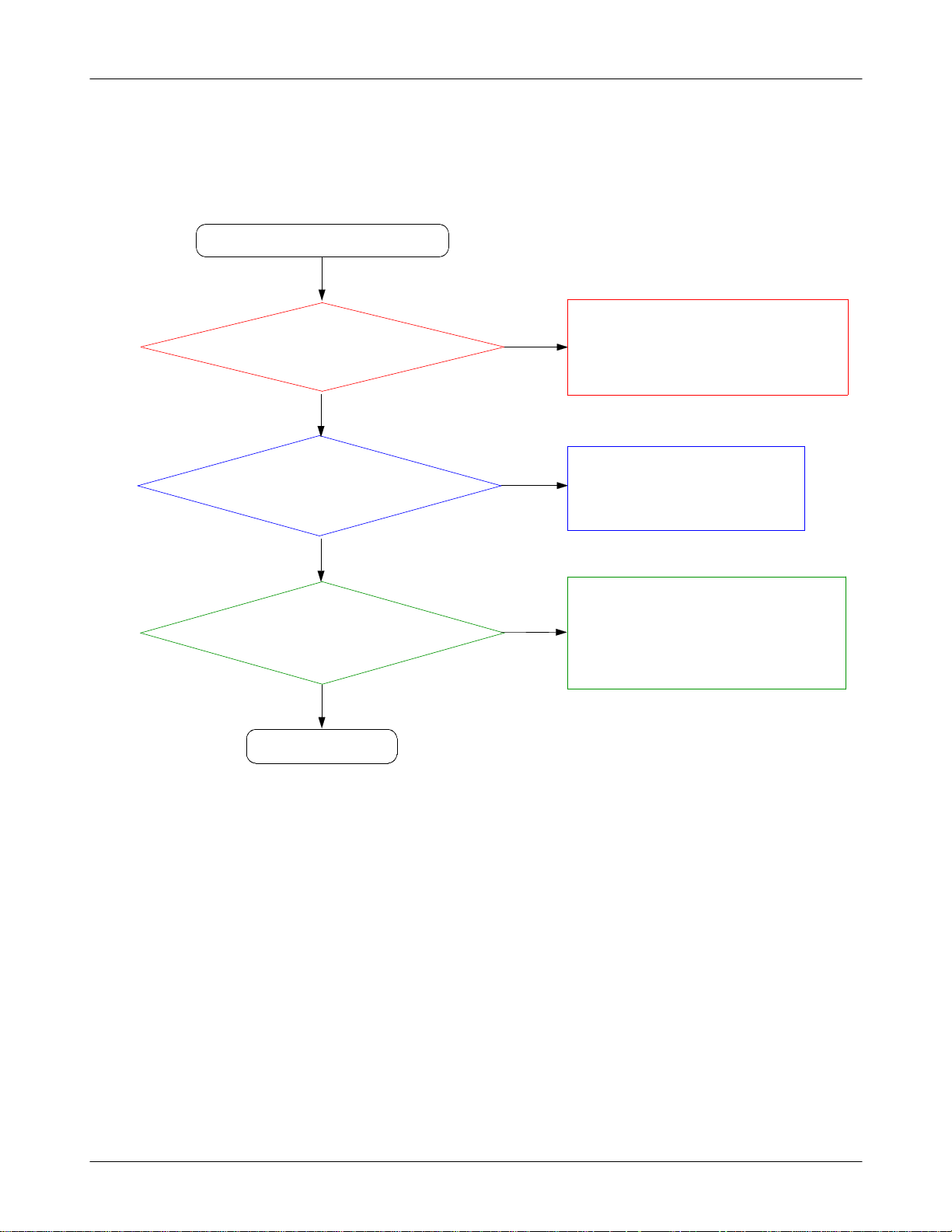
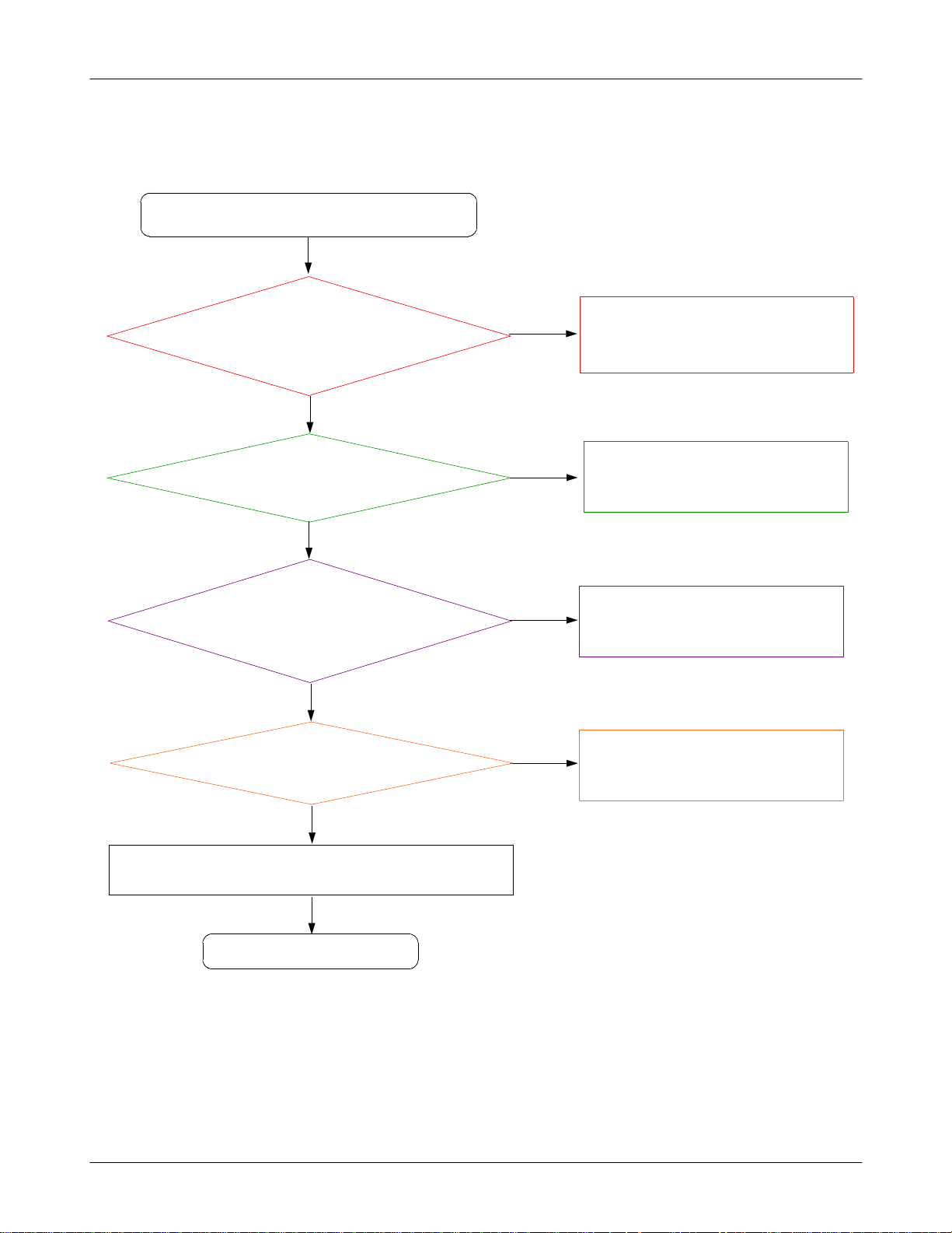
8-3-2.
Initial
Initial Failure
Yes
Check R207(RST_BB
using the oscilloscope
Yes
CheckUCP200pin D2
1.7V ?
TP: HEA4009pin
(
) > 1.7V?
.
>
)
No
No
Resolder the R208.
It must be higher than
Change the UCP200.
1.7
V.
Yes
Check the16bit data signalsare correct.
Yes
END
8-9
SAMSUNG Proprietary-Contents may change without notice
This Document can not be used without Samsung's authorization
Page 10
Level3Repair
FM_LNA_OUT
OSC201
2431
R205
MMCI_DAT2 T2IN
VDD_1.8V
VDD_2.9V
HEA400
22
11
4
33
4
FLM_OUT
LED+_12V
LED-
LCD_RST LCD_WR_OUT
LCD_D(0)
LCD_D(1)
LCD_D(2)
LCD_D(3)
LCD_D(4)
LCD_D(5)
LCD_D(6)
5566
7788
99
11111212
1313 14 14
15151616
1717 18 18
1919
2121
23232424
2525 2626
27272828
29
29
C
C
C
N
N
N
2
1
3
3
3
3
C431
C428
LCD_RS_OUT
LCD_CS_OUT
LCD_RD
1010
20
20
2222
LCD_D(7)
3030
C
N
4
3
2.2" QVGA LCD
8-10
SAMSUNG Proprietary-Contents may change without notice
This Document can not be used without Samsung's authorization
Page 11
Level3Repair
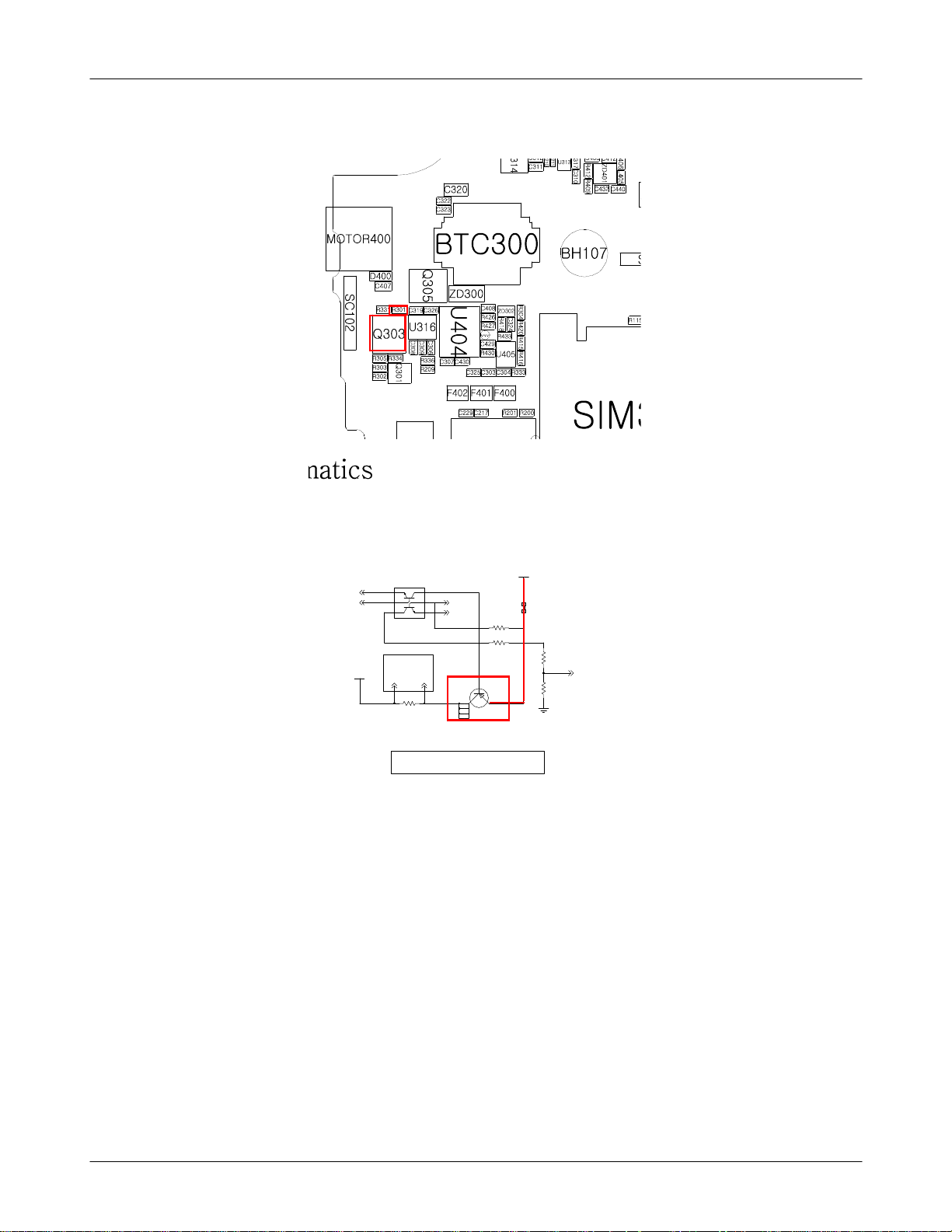
8-3-3.
Charging Part
Check the R301
Abnormal charging part
Yes
Check the Battery&TA
connection.
Yes
>4.9V?
Yes
No
No
Reinsert the Battery or TA.
Resolder the R301
Check the Q303 pin
>4.9V ?
Yes
END
3
No
Replace the Q303 usingaHeatgun
8-11
SAMSUNG Proprietary-Contents may change without notice
This Document can not be used without Samsung's authorization
Page 12
Level3Repair
CS
VBAT
Q301
1
6
2
5
34
Routed as a Pair FROM R315(0.1T)
N
_
E
S
N
E
S
R331
TNHSVBSC
VDDCHG
R302
R303
P
_
E
S
N
E
S
3
4
Q303
CHARGING CIRCUIT
VBUS_5V_OUT
R301
R305
VCHG
R334
8-12
SAMSUNG Proprietary-Contents may change without notice
This Document can not be used without Samsung's authorization
Page 13
Level3Repair
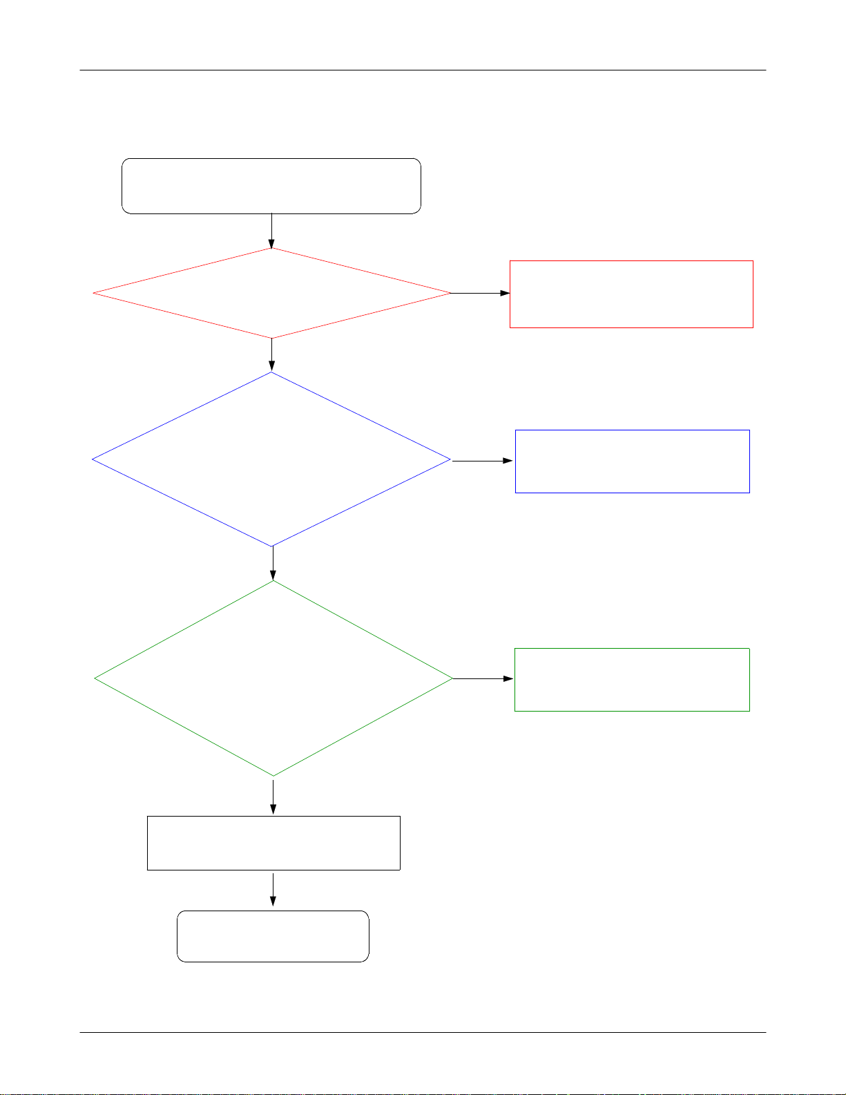
8-3-4.
Sim Part
Phone can't access SIM Card
Yes
Check the
SIM
Check the SIM_CLK signal is on.
method:wire the pin3(C303)
(
and check its waveform using an
pin1(C325)
300
After Power ON,
C303)
(TP:
oscilloscope)
Yes
】
2.85V
No
No
Resolder the UCP200 using heatgun.
Resolder or Replace SIM300 connector.
Because of not soldering well)
(
Yes
After SIM card insert,
Check the SIM
pin2(R333,C304: SIM_RST)
method:wirethe pin2and
(
check its waveform using an
Check the SIM Card is demaged.
2.85V?
oscilloscope)
END
300
】
Yes
Yes
No
Change the PBA.
8-13
SAMSUNG Proprietary-Contents may change without notice
This Document can not be used without Samsung's authorization
Page 14
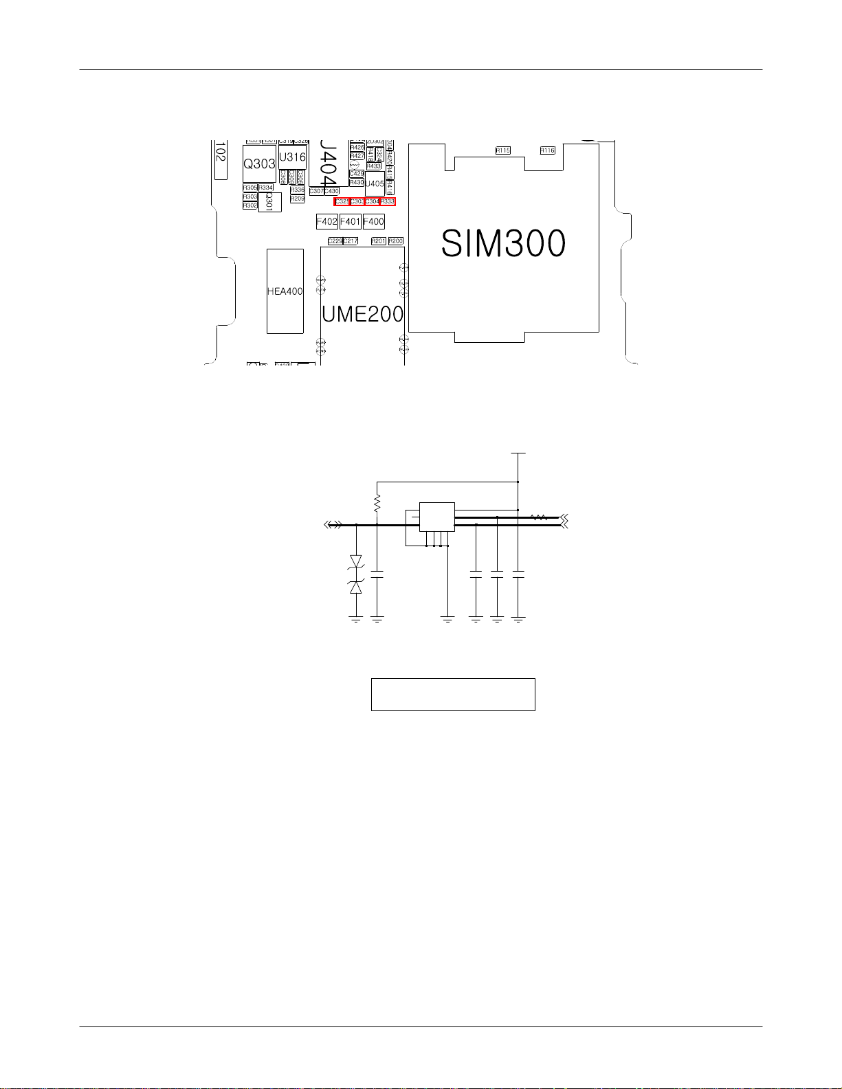
Level3Repair
VSIM_2.85V
SIM300
R332
6
6
11
5
5
4
7GG89GG10
22
33
C303 C304
SIM_IO SIM_CLK
ZD301
4
C302
C325
R333
SIM_RST
SIM SOCKET
8-14
SAMSUNG Proprietary-Contents may change without notice
This Document can not be used without Samsung's authorization
Page 15
Level3Repair
8-3-5.
Microphone Part
Microphone does not work
Check R432
at Mic Active?
Check the MIC signal paths.
MIC signals are on.
L403,L410,C422,
(TP:
C420,R432,R435,R437)
Yes
=2.2V
Yes
No
No
Replace the UCP200 usingaHeatgun
Because of not soldering well
(
Resolder L403, L410, C422, C420, R432, R435,
R437
not work if those is not connected.)
(
)
Yes
Check the MIC is demaged.
Yes
END
No
Replace an another MIC
8-15
SAMSUNG Proprietary-Contents may change without notice
This Document can not be used without Samsung's authorization
Page 16
Level3Repair
A
XAUX
V_MIC_2.2V
R432
C424
C422
C447
R436
C420
C453
MIC_P
MIC_N
AU
P
MIC400
R435
C446
2
C441
0
4
D
Z
3
0
4
D
Z
L403
C448
L410
C451
C450
R437
MAIN MIC
8-16
SAMSUNG Proprietary-Contents may change without notice
This Document can not be used without Samsung's authorization
Page 17
Level3Repair
8-3-6.
Speaker Part
Check the UCP N15,N16 pin
Speaker does not work
Yes
signals are on.
L405, L406)
(TP:
Yes
Check the SPK signal
paths.
Are signal on?.
C412,C440)
(TP:
No
Replace the UCP200 using the Heatgun.
because of soldering not well)
(
No
Resolder the L405, L406.
Yes
Check the Speaker module
is Okay.
Yes
END
No
Replace the SPK module.
8-17
SAMSUNG Proprietary-Contents may change without notice
This Document can not be used without Samsung's authorization
Page 18

Level3Repair
ZD401
SPK_P
SPK_N
4
6
SPK400
L405
L406
C440C412
SPK / RCV
F400
8-18
SAMSUNG Proprietary-Contents may change without notice
This Document can not be used without Samsung's authorization
Page 19

Level3Repair
8-3-7.
RCV Part
Receiver does not work
Yes
Check the UCP M15,M16
pin signal is on.
R412, R409)
(TP:
Yes
Check the RCV signal
paths
Are signals on?.
C432,C433)
(TP:
No
Replace the UCP200 using the Heatgun.
because of soldering not well)
(
No
Resolder the R412, R409.
Yes
Check the RCV module is
Okay.
Yes
END
No
Replace the RCV module.
8-19
SAMSUNG Proprietary-Contents may change without notice
This Document can not be used without Samsung's authorization
Page 20

Level3Repair
RCV_P
RCV_N
R412
R409
RCV400
1
1
2
2
C433C432
3
1
5
2
ZD401
4
6
MIC400
8-20
SAMSUNG Proprietary-Contents may change without notice
This Document can not be used without Samsung's authorization
Page 21

Level3Repair
8-3-8.
EAR_Speaker Part
Ear_Speaker is not working.
Check the earphone connector is
demaged.
Check the L404
Check EarAmp enable signal is
(TP:
Check the Ear signals are on,
while playing the sound.
(TP:
Yes
=0V
Yes
correct.
R336
=1.8
Yes
C308, C309)
Yes
V)
No
No
No
Resolder the L404 or Replace the EAR
connector(EAR400)
Resolder the R336 or Replace the UCP200.
Resolder the C308, C309 or Replace the
UCP200.
Check the Ear signals passing
the Ear AMP are on, while
playing the sound.
R404, R403)
(TP:
Yes
Check the ear signal paths
Are signals on?.
L401,L400)
(TP:
Yes
Check EAR400 pin
demaged.
Yes
Change the EAR400.
Yes
END
6, 7
is
No
No
No
Resolder the Ear AMP(U316).
Resolder the R404, R403, L401, L400.
Change the Ear phone.
8-21
SAMSUNG Proprietary-Contents may change without notice
This Document can not be used without Samsung's authorization
Page 22

Level3Repair
MOTOR400
2
2
1
1
MOTOR
V_MOT_3.3V
C407
EAR400
CON-A
2
CON-B
3
CON-F
7
CON-E
6
CON-D
5
CON-C
4
D400
L402
L401
L400
1
6
5
4
3
ZD400
2
R404
R403
C403C402
3.5PI EAR JACK
VDD_1.8V
R414
L404
C452
3.5_DETECT3.5_CON_DETECT
R412
RCV_P
RCV_N
R409
SEND_END
EAR_MIC_P
FM_ANT_EAR
EAR_3.5_L
EAR_3.5_R
3.5_CON_DETECT
C405
C404
C433C432
3
5
1
2
ZD401
EAR_SPK_L
EAR_SPK_R
C306 C307
C308
C309
VDD_1.8V
3
4
C326
C
C
D
D
V
A3
P
C1N
A4
C1P
C1
INL
C2
INR NC
S
D
S
N
V
G
P
3
2
B
A
C319
EAR_AMP
N
I
V
P
OUTR
_SHDN
4
B
U316
B1
OUTL
A1
B2
1
D
2
NC
N
G
P
EAR_3.5_L
EAR_3.5_R
EN_EAR_AMP
R336
8-22
SAMSUNG Proprietary-Contents may change without notice
This Document can not be used without Samsung's authorization
Page 23
Level3Repair
8-3-9.
EAR_MIC Part
Ear_Microphone is not working.
Check the EAR connector is
(TP:
Check the Ear_Mic voltage is on.
Yes
demaged.
L402 signal is on.)
Yes
R421
(TP:
=2.2
Yes
V)
No
No
Resolder the L402 or Replace the EAR
connector(EAR400)
Resolder the R421 or Replace the UCP200.
Check the signal paths
Are signals on?.
C434, C423, R431, R422)
(TP:
Yes
Check the UCP200 is demaged.
Yes
Resolder the UCP200 using the heatgun.
Yes
END
No
Resolder the C434, C423, R431, R422
No
Check the EAR phone.
8-23
SAMSUNG Proprietary-Contents may change without notice
This Document can not be used without Samsung's authorization
Page 24
Level3Repair
EAR400
C404
SEND_END
EAR_MIC_P
FM_ANT_EAR
EAR_3.5_L
EAR_3.5_R
3.5_CON_DETECT
CON-A
2
CON-B
3
CON-F
7
CON-E
6
CON-D
5
CON-C
4
5
6
L402
L401
L400
3
1
4
ZD400
2
R404
R403
C403C402
C405
3.5PI EAR JACK
V_EARMIC_2.2V
R421
R422
100nFC434
10V
EAR MIC
C435
R431
EAR_MIC_PAUX_MIC_P
AUX_MIC_N
PARALLEL
C419 TA400
1005
C449
C423
R424
8-24
SAMSUNG Proprietary-Contents may change without notice
This Document can not be used without Samsung's authorization
Page 25

Level3Repair
8-3-10.
Vibrator Part
Check the Enable signal is
Check the motor operating
Vibrator does not work
Yes
on.
R313 is not0V)
(TP:
Yes
voltage
(TP:
=3.3
C314)
V.
No
Resolder the UCP200 using the heatgun.
No
Resolder the U315.
Yes
Change the Motor module.
Yes
END
8-25
SAMSUNG Proprietary-Contents may change without notice
This Document can not be used without Samsung's authorization
Page 26
Level3Repair
VBAT
MOT_EN
C313
R313
KEY / MOT LDO
MAIN_KEY_3.3V
V_MOT_3.3V
U315
1
6VOUT1
VIN
2
5
GND
VOUT2
3
4
EN2
EN1
GND
7
0
1
3
L
EN_MAIN_KEY_LDO
C315
C314
R314
MOTOR400
V_MOT_3.3V
2
2
1
1
D400C407
MOTOR
8-26
SAMSUNG Proprietary-Contents may change without notice
This Document can not be used without Samsung's authorization
Page 27

Level3Repair
8-3-11.
SD_Card Part
SD card does not work.
Check the Vdd_IO=1.8V.
Check VMMC_2.85
Check the Pull-up Registor is
(TP:
R320, R321 are not0V.)
Yes
R321)
(TP:
R316)
(TP:
Yes
soldered well.
R316, R317, R318, R319,
Yes
=2.85
V.
No
No
Replace the UCP200.
Resolder the R316, R317, R318, R319,
R320, R321.
Check the SD_CLK is on.
SD3005pin)
(TP:
Yes
Check the SD300 is demaged.
Yes
Resolder the SD300 using the heatgun.
Yes
END
No
Resolder the UCP200.
No
Check the SD card is demaged.
8-27
SAMSUNG Proprietary-Contents may change without notice
This Document can not be used without Samsung's authorization
Page 28

Level3Repair
DETECT_SD
SD_DATA(1)
SD_DATA(0)
SD_CLK
SD_CMD
SD_DATA(3)
SD_DATA(2)
VMMC_2.85V
C321
R317
R316 R318 R319
VDD_IO1_1.8V
R320
R321
T-FLASH SOCKET
C329
20
19
18
17
16
15
14
13
12
11
10
NC
NC
NC
NC
NC
NC
NC
NC
CD
COMMON
GND
GND
9
DAT1
8
DAT0
7
VSS
6
CLK
5
VDD
4
CMD
3
DAT3|CD
2
DAT2
1
SD300
8-28
SAMSUNG Proprietary-Contents may change without notice
This Document can not be used without Samsung's authorization
Page 29
Level3Repair
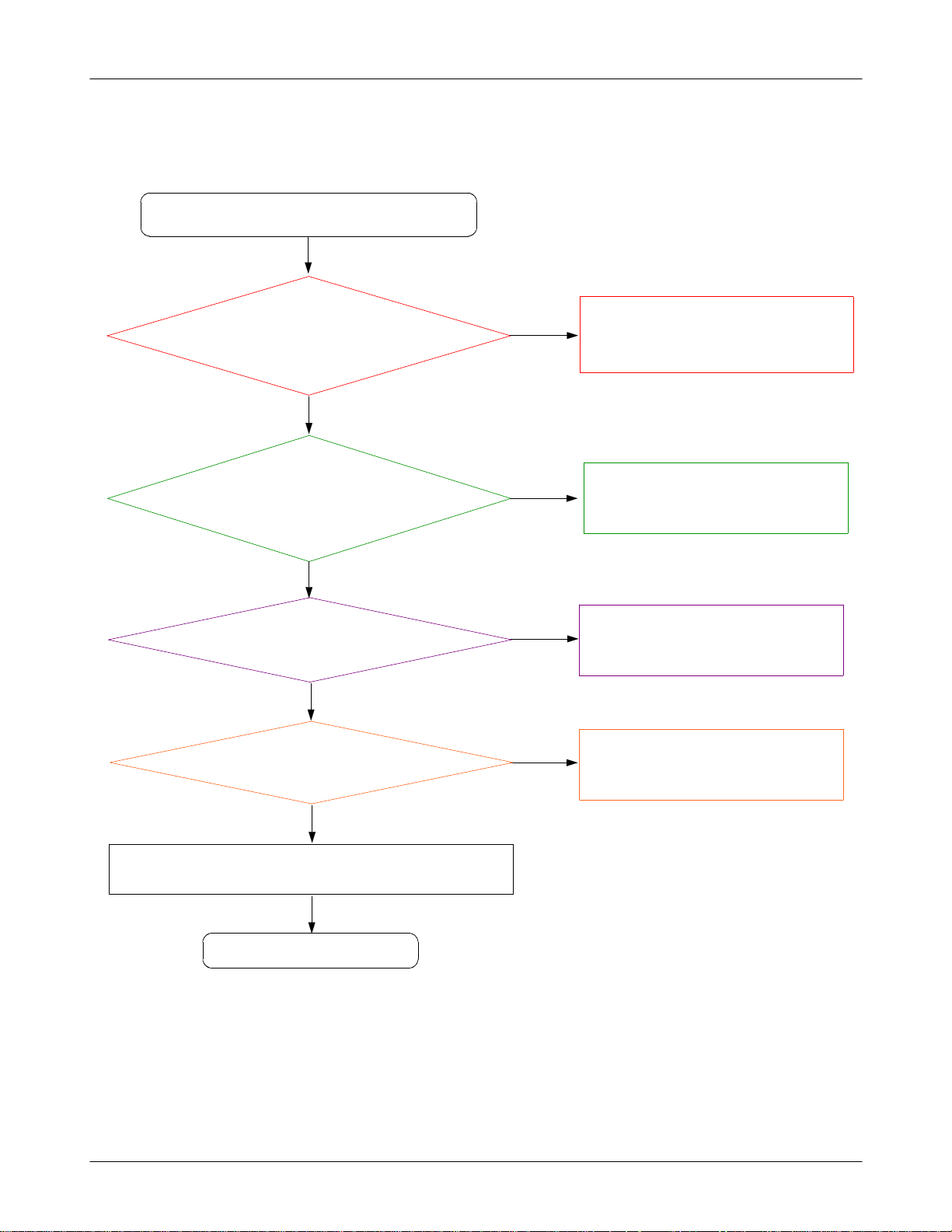
8-3-12.
Camera Part
Check the Camera Enable signal
Check the Camera operating
(TP:
Camera does not work.
Yes
is High.
R315
(TP:
voltage is correct.
C317
=1.2
C312
=2.8
=1.8
Yes
V, C311
V)
Yes
V)
=1.8V
No
Replace the UCP200, using the heatgun.
If C317 is not
No
If C311, C312 is wrong, Replace the U314.
V, Replace the U313.
1.8
Check CAM_RST is high,as soon
as camera works.
TP_CAM_RST
(TP:
Yes
Check the Camera is demaged.
Yes
Change the Camera module.
Yes
END
=1.8
V)
No
Replace the UCP200, using the heatgun.
No
Change the CN400.
8-29
SAMSUNG Proprietary-Contents may change without notice
This Document can not be used without Samsung's authorization
Page 30
Level3Repair
EN_CAM_PWR
VBAT
4
3
C310
U313
VDD1VOUT
D
CE
N
G
5
VCAM_A_2.8V
U314
VCAM_IO_1.8VVCAM_CORE_1.2V
6
VOUT2
5
4
D
VSS
N
G
7
C311
C312
VBAT
EN_CAM_PWR
2
GND
C317
1
EN2
VIN2VOUT1
3
EN1
R315
C330
3M CAM LDO
VCAM_CORE_1.2V
CAM_RST
CAM_PCLK_IN
CAM(2)
CAM(1)
CAM(0)
CAM_SDA
CAM_SCL
CAM(3)
CAM(4)
CAM(5)
CAM(6)
CAM(7)
CAM_HSYNC
CAM_VSYNC
CAM_MCLK_OUT
3M CAM SOCKET
VCAM_IO_1.8V
TP_CAM_RST
VCAM_A_2.8V
CN400
1
1
2
2
3
3
4
4
5
5
6
6
7
7
8
8
9
9
10
10
11
11
12
12
13
13
14
14
15
15
16
16
17
17
18
18
19
19
20
20
21
21
22
22
23
23
24
24
25
25
26
26
27
27
28
28
29
29
30
30
31
31
32
32
R434
8-30
SAMSUNG Proprietary-Contents may change without notice
This Document can not be used without Samsung's authorization
Page 31
Level3Repair
8-3-13.
FM Radio Part
FM radio does not work.
Check the FM ant signal is GND.
Check the FMR LNA operating
(TP:
Check the FMR_LNA_SW is high.
TP_FM_LNA_SW
(TP:
Yes
L124=0V)
(TP:
Yes
voltage is correct.
C130
=2.9
Yes
V)
=1.8
V)
No
Resolder the L124.
No
Replace the UCP200.
No
Replace the UCP200.
Yes
Resolder the U100, C133, L121,
C121, R108, R109, R110.
Yes
END
No
Replace the UCP200.
8-31
SAMSUNG Proprietary-Contents may change without notice
This Document can not be used without Samsung's authorization
Page 32

Level3Repair
FM_ANT_EAR
L124
C133
C131
VDD_2.9V
L121
C129 C130
FMR LNA
C121
U100
1
CURRENT-AD
VCC
BIAS-OUT
3
RF-IN RF-OUT
S
S
V
7
CTRL-SW
R108
R110R109
6
52
4
TP_FM_LNA_SW
FM_LNA_SW
FM_LNA_OUT
8-32
SAMSUNG Proprietary-Contents may change without notice
This Document can not be used without Samsung's authorization
Page 33

Level3Repair
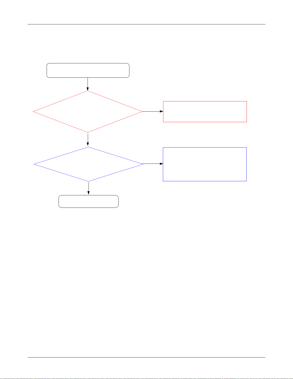
8-3-14.
Bluetooth Part
Bluetooth does not work.
Check Operatiog voltage is Okay.
Check26Mhz Clock is on.
Check the Vbt_1.5V is on.
(TP:
(TP:
C116=1.8V)
(TP:
L122
Yes
Yes
C123)
Yes
=1.5
V)
No
Replace the UCP200.
No
Resolder the C123 or replace the UCP200.
No
Replace the U101.
Yes
Change the BT ant path elements.
Resolder the F102, C101,
(
ANT102)
Yes
END
No
Replace the UCP200.
8-33
SAMSUNG Proprietary-Contents may change without notice
This Document can not be used without Samsung's authorization
Page 34

Level3Repair
BT_REQ_CLK
PCM_TXD
PCM_RXD
PCM_CLK
PCM_SYNC
UART2_RXD
UART2_TXD
C118 C119
TP_UART100
TP_UART101
TP_REQ_CLK
C120
B4
AIO0
C4
PIO0
B5
PIO1
C5
PIO2
C6
PIO3
E7
PIO4
B7
PIO5
D5
PIO7
C7
PIO9
G4
PCM_IN
H2
PCM_OUT
H3
PCM_CLK
H4
PCM_SYNC
G7
SDIO_DATA0|CSPI_MISO|UART_TX
F6
SDIO_DATA1|CSPI_INT|UART_RTS
F7
SDIO_DATA2|UART_RX
G6
SDIO_DATA3|CSPI_CS#|UART_CTS
H7
SDIO_CLKCSPI_CLK
D6
SDIO_CMDCSPI_MOSI
E5
SDIO_SD_CS#
E6
CLK_32K
R113
R107
3
C
1
A
U102
A
N
A
_
S
S
V
6
B
VDD_1.8VVBT_1.5V VDD_1.8V
7
6
7
D
A
H
E
A
S
R
N
D
A
A
O
_
P
C
_
D
_
D
D
D
V
D
D
V
V
G
G
I
I
O
L
D
D
_
_
_
S
S
S
S
S
S
V
V
V
5
1
1
E
H
C
C116
1
G
S
O
I
D
D
A
A
P
R
_
_
D
H1
D
D
SPI_CLK
D
V
V
E4
SPI_CS#
F4
SPI_MISO
G2
SPI_MOSI
A5
VREGIN_H
B2
VREGIN_L
A4
VREGOUT_H
A6
VREGENABLE
E2
RF_N
F2
RF_P
A3
XTAL_IN
A2
XTAL_OUT
G3
RST#
B3
LO_REF
G5
TEST_EN
C2
N|CS
D2
N|CS
D4
N|CS
F5
N|CS
1
NC
2
N
E
NC
O
I
E
D
R
A
C
R
S
_
_
S
S
S
S
V
V
3
F
C117
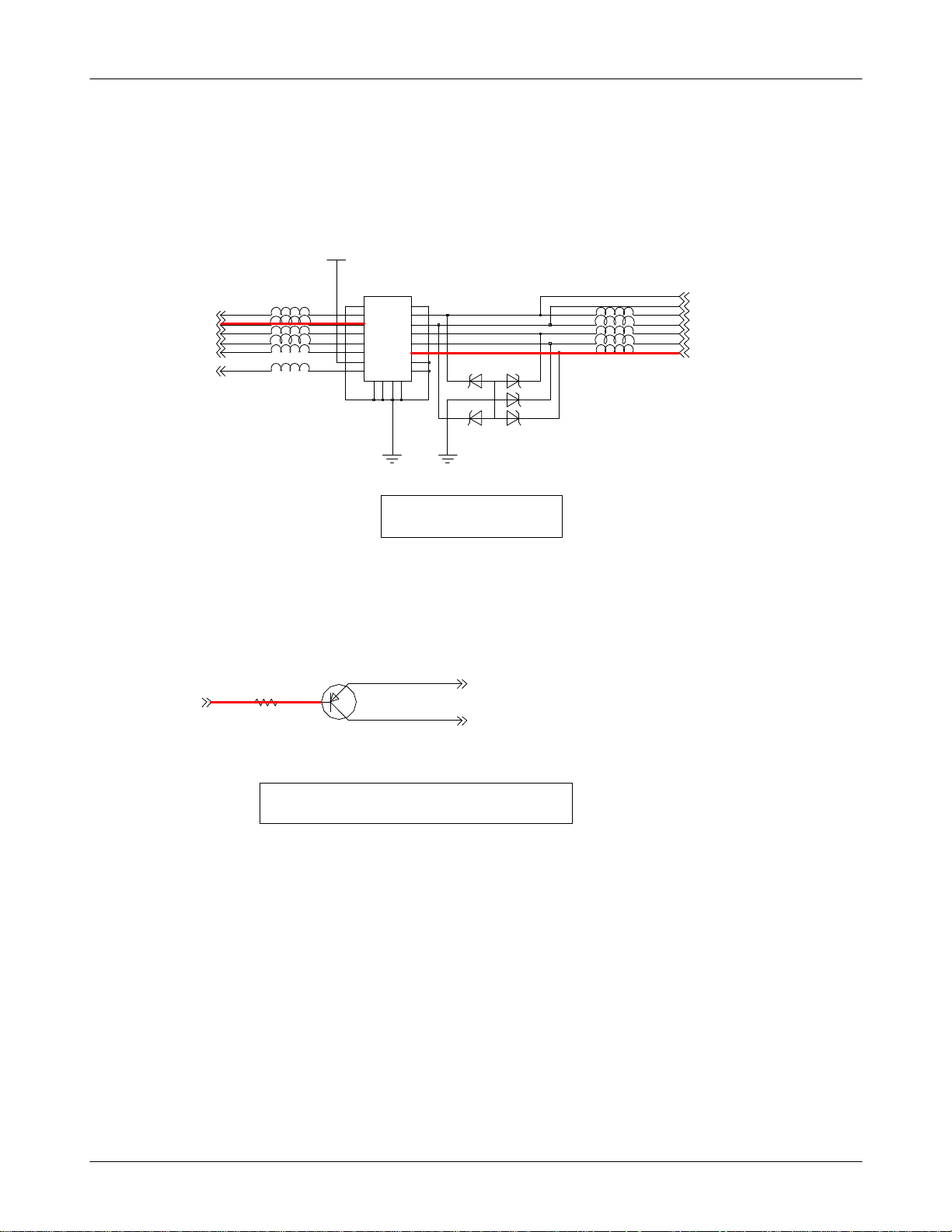
F102
8
3
G57G
GNC
C101
1
6
UNBAL
BAL
BAL
C123
CLK26M_BT
BT_RST
DC
4
VBT_1.5V
2
C124
L122
ANT102
132
C128
C132
BT
8-34
SAMSUNG Proprietary-Contents may change without notice
This Document can not be used without Samsung's authorization
Page 35
Level3Repair
8-3-15.
Key Data Input
Check Initial Operation
When you pushed all of the
Key, does the key have
Yes
tension?
Yes
No
(#1 :
whether be sunken
look over the Dome location
#2 :
whether be out of line)
Change Domesheet
look over the Dome situation
All of the key doesn't work
except POWER ON KEY
Yes
END
No
?
because of be possible for PBA to get damaged)
Replace the PBA
over the insturctions again
(
and change the board
8-35
SAMSUNG Proprietary-Contents may change without notice
This Document can not be used without Samsung's authorization
Page 36
Level3Repair
KEY_COL(4)
KEY_COL(3)
KEY_COL(2)
KEY_COL(1)
KEY_COL(0)
ONKEY_N
L305
L306
L307
L308
L309
L311
MAIN_KEY_3.3V
13
HEA300
11
3344
5566
7788
99
1111 1212
131414
151516
C
C
C
N
N
N
7
9
8
1
1
1
22
1010
16
C
N
0
2
1
2
3
6
5
4
L300
L301
L302
L303
L304
VOL_KEY_ROW(0)
VOL_KEY_ROW(1)
KEY_ROW(0)
KEY_ROW(1)
KEY_ROW(2)
KEY_ROW(3)
KEY_ROW(4)
ZD304
ONKEY_N
MAIN KEY
Q304
R306
POWER ON CIRCUIT
2
1
3
KEY_COL(3)
KEY_ROW(4)
8-36
SAMSUNG Proprietary-Contents may change without notice
This Document can not be used without Samsung's authorization
Page 37
Level3Repair
8-3-16.
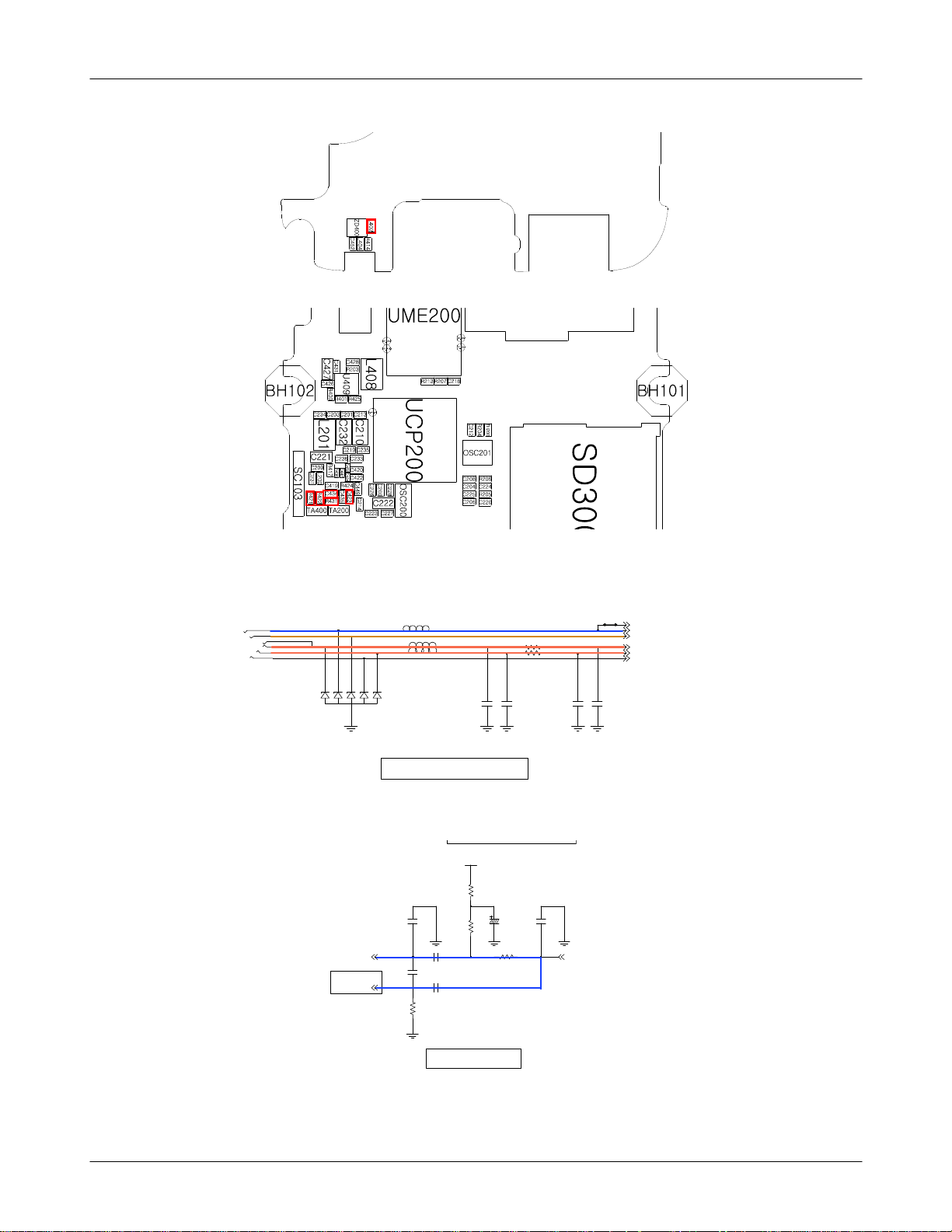
Back Light(for Color Main LCD)
Backlight does not work
Yes
Is LCD Contrast set on high
level in the Menu?
menu->settings->display-
(
Brightness->level
>
Is R40
=1.8V?
Wiring U409 pin3,
(
EN_LCD_BL)
)
Yes
No
No
Set LCD Contrast on high level
menu->settings->display->Brightness->level
(
select5Level(level
Resolder R400
#1 :
with an soldering iron)
(
Repalce LCD Module
#2 :
to check if it has the problem)
(
:1~5)
/
END
Yes
8-37
SAMSUNG Proprietary-Contents may change without notice
This Document can not be used without Samsung's authorization
Page 38

Level3Repair
VBAT
L408
U409
6
GND
5
SW
4
FB
VOUT
D
N
G
1
2
VIN
3
EN
7
LED+_12V
EN_LCD_BLLED-
R425R401
C426
C427
R400
8-38
SAMSUNG Proprietary-Contents may change without notice
This Document can not be used without Samsung's authorization
Page 39

Level3Repair
8-3-17.
Key Back Light
Main Key LED does not work
Check the Key LDO enable is
(TP:
Check the Main key voltage
(TP:
Yes
high.
R314
is high.
L310
=1.8
Yes
=3.3
V)
V)
No
No
Replace the UCP200 usingaHeatgun
Replace the U315 usingaHeatgun
Yes
Key LED does not work?
look over the LED light)
(
Yes
END
No
Replace the LED
be possible that the sample has the problem)
(
#1 :
#2 :
Change PBA
8-39
SAMSUNG Proprietary-Contents may change without notice
This Document can not be used without Samsung's authorization
Page 40

Level3Repair
MOT_EN
V_MOT_3.3V
VBAT
U315
R313
1
2
3
C313
VIN
GND
EN2
GND
7
VOUT2
6VOUT1
5
4
EN1
KEY / MOT LDO
MAIN_KEY_3.3V
C314
0
1
3
L
EN_MAIN_KEY_LDO
C315
R314
8-40
SAMSUNG Proprietary-Contents may change without notice
This Document can not be used without Samsung's authorization
Page 41

Level3Repair
presetting
(
Rx setting)
(
Active Cell
1.
select GSM or GPRS
:
Connetion Type
2.
select Auto(GSM), BLER(GPRS)
:
BCH Parameter
3.
select measuring band(DCS or EGSM)
:
Cell power
4.
dBm
:-60
8960
8-41
SAMSUNG Proprietary-Contents may change without notice
This Document can not be used without Samsung's authorization
Page 42

Level3Repair
Tx setting)
(
After setting
(
After setting, prepare the call setup Display
1.
UsinganOriginateCall,makeacall.
2.
Confirm the display"connected"
3.
start the measuring
4.
8960 (
EGSM/DCS
)
8-42
SAMSUNG Proprietary-Contents may change without notice
This Document can not be used without Samsung's authorization
Page 43
Level3Repair
(
8960 &
spectrum analyzer
down&up at picture)
(
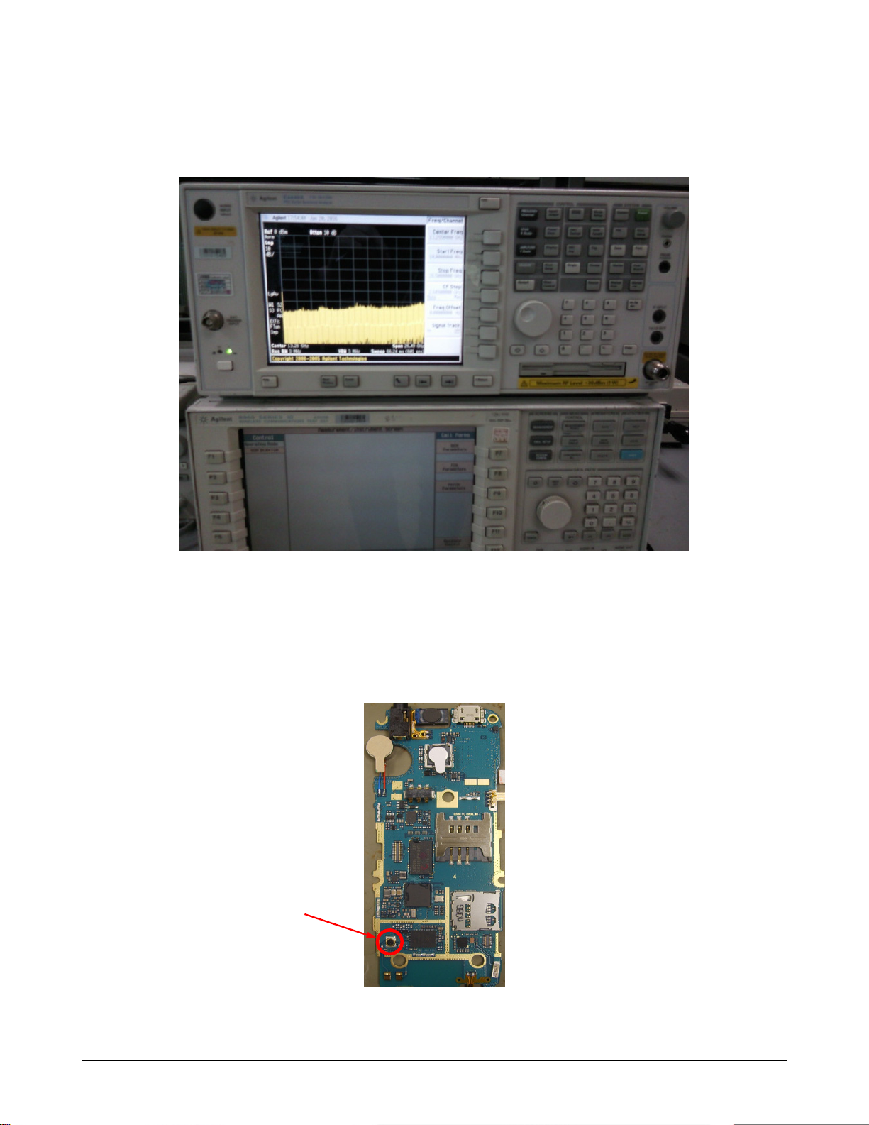
spectrum analyzer:testing method=the way using an Osciliscope
-
-8960:
connect using RF Cable between
8960 &
RF Connector in board.
RF Connector
8-43
SAMSUNG Proprietary-Contents may change without notice
This Document can not be used without Samsung's authorization
Page 44

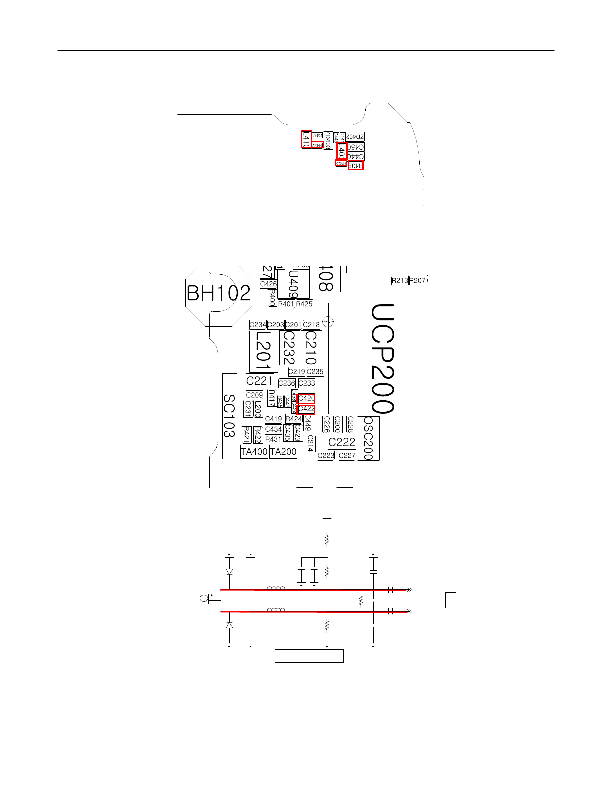
Level3Repair
8-3-10.
GSM
Cell Power
PAM101
(
spectrum analyzer)
PAM101 Pin11
(
specturm analyzer)
TCXO CLOCK
MHz@OSC201
26
Receiver
850
RX ON
:-60
Yes
Pin
dBm
-65
TP:L120 using
Yes
dBm
-68
TP:L108 using
Yes
CHECK?
pin
1,3
17
dBm
No
No
No
Resolder PAM101, C134, L129,
C100, L120)
Check PAM101
pin
pin6=
5=L,
Resolder OSC201
L
No
Yes
Check ANT Switch
or ANT is demaged.
Resolder PAM101
Yes
Check UCP20
Yes
END
0
8-44
SAMSUNG Proprietary-Contents may change without notice
This Document can not be used without Samsung's authorization
Page 45

Level3Repair
8-3-11.
GSM
Cell Power
PAM101
(
spectrum analyzer)
PAM101 Pin12
(
specturm analyzer)
TCXO CLOCK
MHz@OSC201
26
Receiver
900
RX ON
:-60
Yes
Pin
dBm
-65
TP:L120 using
Yes
dBm
-68
TP:L109 using
Yes
CHECK?
pin
1,3
17
dBm
No
No
No
Resolder PAM101, C134, L129,
C100, L120
Check PAM101
pin
Resolder OSC201
5=L,
pin6=H
No
Yes
Check ANT Switch
or ANT is demaged.
Resolder PAM101
Yes
Check UCP20
Yes
END
0
8-45
SAMSUNG Proprietary-Contents may change without notice
This Document can not be used without Samsung's authorization
Page 46

Level3Repair
8-3-12.
DCS Receiver
RX ON
Cell Power
PAM101
(
spectrum analyzer)
PAM101 Pin13
(
specturm analyzer)
TCXO CLOCK
MHz@OSC201
26
:-60
Yes
Pin
17
dBm
-65
TP:L120 using
Yes
dBm
-68
TP:L110 using
Yes
CHECK?
pin
1,3
dBm
No
No
No
Resolder PAM101, C134, L129,
C100, L120
Check PAM101
pin5,pin6=H
Resolder OSC201
No
Yes
Check ANT Switch
or ANT is demaged.
Resolder PAM101
Yes
Check UCP20
Yes
END
0
8-46
SAMSUNG Proprietary-Contents may change without notice
This Document can not be used without Samsung's authorization
Page 47

Level3Repair
8-3-13.
PCS Receiver
RX ON
Cell Power
PAM101
(
spectrum analyzer)
PAM101 Pin14
(
specturm analyzer)
TCXO CLOCK
MHz@OSC201
26
:-60
Yes
Pin
17
dBm
-65
TP:L120 using
Yes
dBm
-68
TP:L111 using
Yes
CHECK?
pin
1,3
dBm
No
No
No
Resolder PAM101, C134, L129,
C100, L120
Check PAM101
pin
Resolder OSC201
5=H,
pin6=
L
No
Yes
Check ANT Switch
or ANT is demaged.
Resolder PAM101
Yes
Check UCP20
Yes
END
0
8-47
SAMSUNG Proprietary-Contents may change without notice
This Document can not be used without Samsung's authorization
Page 48

Level3Repair
8-48
SAMSUNG Proprietary-Contents may change without notice
This Document can not be used without Samsung's authorization
Page 49
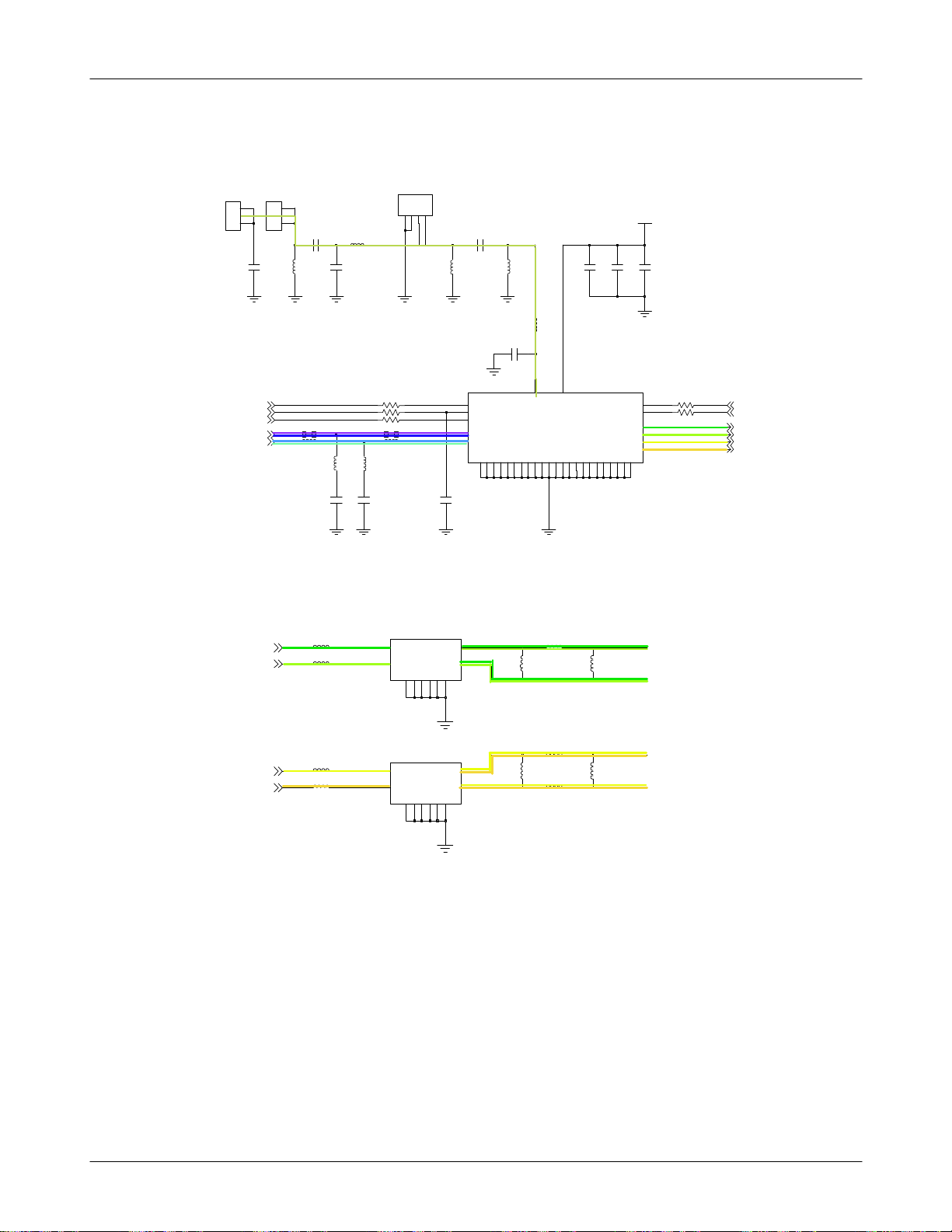
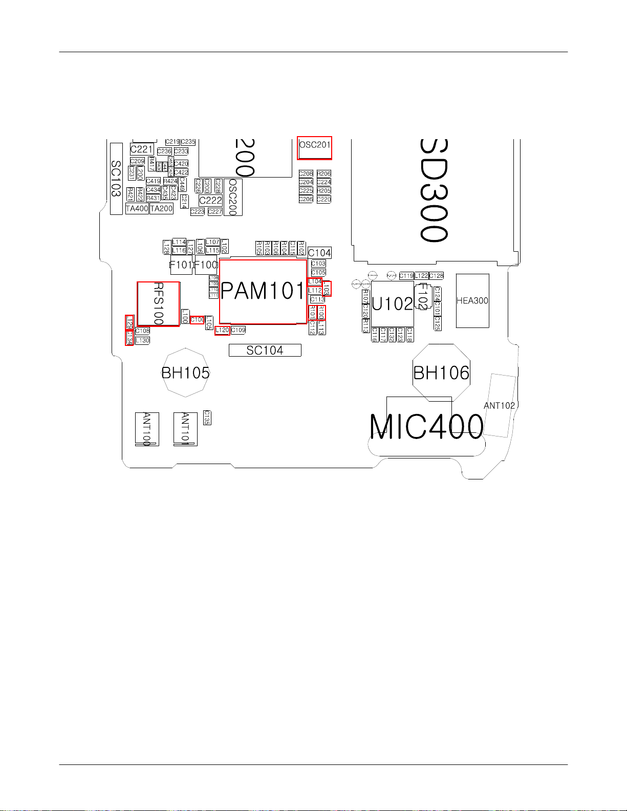
RFS100
ANT101
ANT100
1
1
1
1
2
2
2
2
C135
VLOGIC BS1
RAMP
TX_EN
LB_TX
HB_TX
L130
C134
L129
C108
L113
L112
R102
R104
R106
R101R100
G
G
C
A
3
1
4
2
C100
VLOGIC
VRAMP
TX_EN
GSM_IN
DCS|PCS_IN
G
G
7
1
L105
L120
C109
0
7
3
1
T
T
N
T
A
A
B
V
PAM101
G
G
G
0
8
1
9
G
G
G
G
G
G
9
8
5
6
1
1
1
1
G
G
G
G
G
3
2
8
6
1
0
5
4
2
2
2
2
2
2
2
2
L100
2
3
4
27
401L301L
29
VBAT
C103 C104
C105
5
R103
BS1
6
BS2
R105
11
RX1
12
RX2
13
RX3
14
RX4
G
G
G
G
G
G
G
1
3
2
6
5
4
3
3
3
3
3
3
Level3Repair
BS2
GSM850_RX
GSM900_RX
DCS1800_RX
PCS1900_RX
GSM850_RX
GSM900_RX
DCS1800_RX
PCS1900_RX
L108
L109
L110
L111
C112
C113
4
1
4
1
UNBAL
UNBAL
UNBAL
UNBAL
C115
F100
BAL1
9
BAL2
G
G
G
G
G
G
8
7
2
5
3
0
1
F101
6
BAL1
9
BAL2
G
G
G
G
G
G
8
2
7
5
3
0
1
L115
L116
L102
L106
L127
L128
L114
L107
LB_RX_N
LB_RX_P
HB_RX_N
HB_RX_P
8-49
SAMSUNG Proprietary-Contents may change without notice
This Document can not be used without Samsung's authorization
Page 50

Level3Repair
8-3-14.
GSM
GSM900 Transmitter
850/
TX Power is too Low!!
TX ON(5Level)
26
PAM101 pin
spectrum analyzer)
Check the Voltage
TCXO CLOCK
CHECK?
MHz@OSC201
pin
1,3
YES
27-4
dBm
TP:R101 using
(
YES
C104
<3.3
V?
NO
solder OSC201
Re-
NO
NO
solder or change
Re-
UCP200
Check the UCP200&VBAT
circuit.
YES
PAM101
(
spectrum analyzer)
Check the RFS100
connection with PCB?
re-solder or change
Pin
17
dBm
30
TP:L120 using
YES
YES
Antenna
NO
Resolder PAM101
NO
Resolder RFS100.
8-50
SAMSUNG Proprietary-Contents may change without notice
This Document can not be used without Samsung's authorization
Page 51
Level3Repair
8-3-15.
DCS/PCS Transmitter
TX Power is too Low!!
TX ON(5Level)
26
PAM101 pin
(
spectrum analyzer)
Check the Voltage
TCXO CLOCK
CHECK?
MHz@OSC201
pin
1,3
YES
29-4
dBm
TP:L104 using
YES
C104
<3.3
V?
NO
solder OSC201
Re-
NO
NO
solder or change
Re-
UCP200
Check the UCP200&VBAT
circuit.
YES
PAM101
Pin
17
dBm
30
TP:L120 using
(
spectrum analyzer)
YES
Check the RFS100
connection with PCB?
YES
Antenna
re-solder or change
NO
Resolder PAM101
NO
Resolder RFS100.
8-51
SAMSUNG Proprietary-Contents may change without notice
This Document can not be used without Samsung's authorization
Page 52

Level3Repair
ANT101
1
1
2
2
VLOGIC BS1
RAMP
TX_EN
LB_TX
HB_TX
ANT100
1
2
C135
RFS100
1
2
C134
L130
L113
L129
C108
L112
R102
R104
R106
R101R100
G
G
C
A
4
1
3
2
C100
L100
L105
L120
C105
VBAT
C103 C104
C109
0
7
3
1
T
2
VLOGIC
3
VRAMP
4
TX_EN
27
GSM_IN
401L301L
29
DCS|PCS_IN
G
G
G
G
G
G
6
0
5
1
1
8
1
9
1
7
T
N
T
A
A
B
V
PAM101
G
G
G
G
G
G
G
0
8
9
2
1
1
G
G
G
G
G
2
1
3
4
2
2
2
2
G
6
8
5
1
3
2
2
2
2
3
3
3
5
BS1
R103
6
BS2
R105
11
RX1
12
RX2
13
RX3
14
RX4
G
G
G
G
4
6
5
3
3
3
BS2
GSM850_RX
GSM900_RX
DCS1800_RX
PCS1900_RX
C112
C113
C115
8-52
SAMSUNG Proprietary-Contents may change without notice
This Document can not be used without Samsung's authorization
Page 53
Level3Repair
8-53
SAMSUNG Proprietary-Contents may change without notice
This Document can not be used without Samsung's authorization
Page 54

Level3Repair
Service Schematics
8-4.
NC Point(Top View)
-
NC
:
U101
1234567
A
.......
B
C
D
E
F
G
H
......
.......
. ....
.. ....
......
.......
.......
UME200
12345678910
A
B
. .....
C
. .... .
D
E
F
G
H
J
K
L
M
N
P
R
T
U
. ... ..
..
.. .
.........
.........
..........
..........
........
.....
.. .
.
8-54
SAMSUNG Proprietary-Contents may change without notice
This Document can not be used without Samsung's authorization
Page 55

UCP200
12345678910111213141516
Level3Repair
A
B
C
D
E
F
G
H
J
K
L
M
N
P
R
T
..............
................
.......... .....
.... ... .
... ....... .
.... ...........
.............. .
.... ........ ..
.... ........ ..
........ ... ..
.... ..... ....
... ...... ..
.... . .. ..
..... ..........
................
..............
8-55
SAMSUNG Proprietary-Contents may change without notice
This Document can not be used without Samsung's authorization
 Loading...