

Page 1
Disassembly and Assembly Instructions
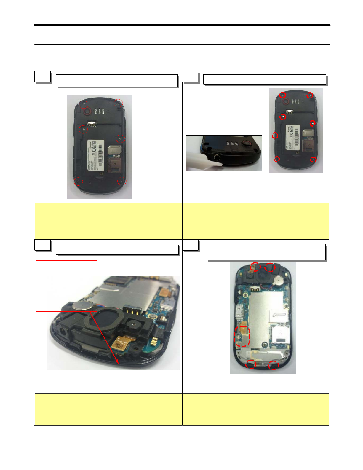
11.
11-1.
Disassembly
1
※
Be careful not to make scratch and molding
1)
damage.
Unscrew the6points.
1)
Caution
2
Be careful not to damage the SMD material.
Don't use DISASSEMBLE JIG deeply.
※
1)
Separate the rear case.
1)
Caution
Be careful not to make scratch and molding
damage.
3 4
After
disassembling the
rear case, check
the TSP FPCB
damage.
※
1)
Perform TSP FPCB visual check
1)
Caution
Be careful not to make damage to INTENNA
Separate the LCD connectors, then
1)
unhook at the4points.
Caution
※
Be careful not to make scratch and molding
1)
damage.
11-1
SAMSUNG Proprietary-Contents may change without notice
This Document can not be used without Samsung's authorization
Page 2
Exploded View and Parts List
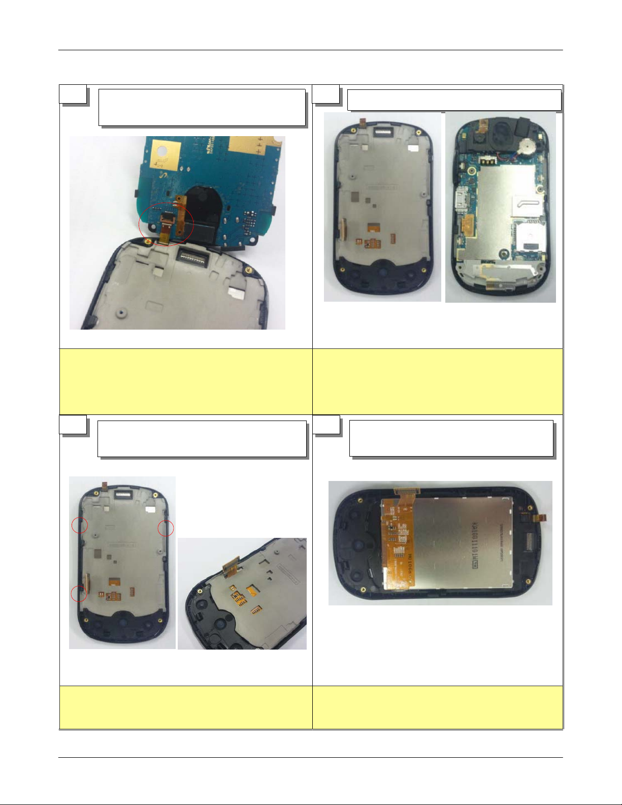
5 6
※
Be careful not to make scratch and molding
1)
After lifting PBA upward,
1)
disassemble TSP FPCB under the board.
Caution
1)
damage.
2)
Separate PBA and the front Assembly.
1)
Caution
※
Be careful not to make scratch and molding
damage.
Be careful not to damage the PBA.
7 8
※
1)
Separate bracket hooks on3points
1)
Separate LCD connector from the bracket.
2)
Caution
Be careful not to damage LCD FPCB.
※
Lift LCD top and separate it from the
1)
front case.
Caution
11-2
SAMSUNG Proprietary-Contents may change without notice
This Document can not be used without Samsung's authorization
Page 3

Exploded View and Parts List
9 10
Caution
※
Be careful not to make intenna hook damage.
1)
Disassemble intenna's left/right hooks
1)
on2points.
1)
Separate camera connector.
1)
Disassemble SPK Carrier's left/right hooks
2)
on2points and remove solder.
Caution
※
Be careful not to make SPK Hook damage.
11 12
※
Be careful not to damage FPCB.
1)
Remove RCV/MIC solder.
1)
Caution
※
Separate the motor/shield can from the
1)
PBA.
Caution
11-3
SAMSUNG Proprietary-Contents may change without notice
This Document can not be used without Samsung's authorization
Page 4

Exploded View and Parts List
11-2.
Assembly
1 2
Caution
※
1)
Assemble the shield can
1)
Solder the motor and speaker module
2)
Be careful not to damage the FPCB.
Solder the receiver and Mic.
1)
Caution
※
1)
Be careful not to damage the receiver FPCB
SPK WIRE.
&
3 4
Caution
※
Confirm receiver's location
1)
Be careful not to make SPK Hook damage.
2)
Solder and assemble the speaker module
1)
and PBA.
Assemble the camera carrier.
1)
Assemble the motor.
2)
Caution
※
Be careful not to damage PBA.
1)
11-4
SAMSUNG Proprietary-Contents may change without notice
This Document can not be used without Samsung's authorization
Page 5

Exploded View and Parts List
5 6
※
1)
Assemble the Intenna to PBA
1)
Caution
Be careful not to make Intenna hook damage.
1) Attach the TSP.
2) Assemble the keypad
Caution
※
Be careful not to damage TSP FPCB
1)
.
7 8
1) Attach and assemble the LCD
Caution
※
Be careful not to damage LCD.
1)
Assemble the bracket.
1)
Caution
※
Be careful not to damage to LCD connector.
1)
11-5
SAMSUNG Proprietary-Contents may change without notice
This Document can not be used without Samsung's authorization
Page 6

Exploded View and Parts List
9 10
Caution
※
Be careful not to damage TSP FPCB.
1)
Assemble TSP FPCB to PBA connector.
1)
1) Locate and make sure of assembly hooks
after placing PBA on the top.
2) Assemble LCD connector
Caution
※
Be careful not to make scratch and molding
1)
damage.
Be careful not to damage TSP FPCB.
)
2
11 12
※
)
1
1) Confirm assembly hooks after assembling
the rear case.
Caution
Be careful not to make scratch and molding
damage.
Screw at6points(Size: M1.4*L3.5)
1)
Screw Torque:
Caution
※
Be careful not to make scratch and molding
)
1
1.0~1.2
Kgfcm
damage.
11-6
SAMSUNG Proprietary-Contents may change without notice
This Document can not be used without Samsung's authorization
 Loading...