

Samsung BN68-03708A User Manual

Contact SAMSUNG WORLDWIDE
If you have any questions or comments relating to Samsung products, please contact the SAMSUNG customer care centre.
Country Customer Care Centre Web Site
AUSTRALIA 1300 362 603 www.samsung.com
NEW ZEALAND 0800 SAMSUNG (0800 726 786) www.samsung.com
CHINA 400-810-5858 www.samsung.com
HONG KONG (852) 3698-4698 www.samsung.com/hk
INDIA
INDONESIA
JAPAN 0120-327-527 www.samsung.com
MALAYSIA 1800-88-9999 www.samsung.com
PHILIPPINES
SINGAPORE 1800-SAMSUNG(726-7864) www.samsung.com
THAILAND
TAIWAN 0800-329-999 www.samsung.com
VIETNAM 1 800 588 889 www.samsung.com
3030 8282
1800 3000 8282
0800-112-8888
021-5699-7777
1-800-10-SAMSUNG(726-7864)
1-800-3-SAMSUNG(726-7864)
1-800-8-SAMSUNG(726-7864)
02-5805777
1800-29-3232
02-689-3232
www.samsung.com
www.samsung.com
www.samsung.com
www.samsung.com
User Manual
© 2011 Samsung Electronics Co., Ltd. All rights reserved.
imagine the possibilities
Thank you for purchasing this Samsung product.
To receive more complete service, please register
your product at
www.samsung.com/register
Model _____________ Serial No. _____________
BN68-03708A-00

Figures and illustrations in this User Manual are provided for reference only and may differ from actual product appearance.
Product design and specifications may be changed without notice.
Still image warning
Avoid displaying still images (like jpeg picture files) or still image element (like TV programme logo, panorama or 4:3 image format, stock or news bar at
screen bottom etc.) on the screen. Constant displaying of still picture can cause ghosting of LCD/LED screen, which will affect image quality. To reduce
risk of this effect, please follow below recommendations:
• Avoid displaying the same TV channel for long periods.
• Always try to display any image on full screen, use TV set picture format menu for best possible match.
• Reduce brightness and contrast values to minimum required to achieve desired picture quality, exceeded values may speed up the burnout process.
• Frequently use all TV features designed to reduce image retention and screen burnout, refer to proper user manual section for details.
Securing the Installation Space
Keep the required distances between the product and other objects (e.g. walls) to ensure proper ventilation.
Failing to do so may result in fire or a problem with the product due to an increase in the internal temperature of the product.
When using a stand or wall-mount, use parts provided by Samsung Electronics only.
✎
If you use parts provided by another manufacturer, it may result in a problem with the product or an injury due to the product falling.
x
The appearance may differ depending on the product.
✎
Be careful when you contact the TV because some parts can be somewhat hot.
✎
Installation with a stand. Installation with a wall-mount.
10 cm
10 cm
10 cm
10 cm
10 cm
10 cm
10 cm
2
English

Contents
P.SIZE
Getting Started
4
Connections
7
Basic Features
10
Advanced Features
16
Other Information
20
4 Accessories
4 Viewing the Control Panel
5 Viewing the Remote Control
6 Connecting to an Antenna
6 Plug & Play (Initial Setup)
7 Connecting to an AV Device
8 Connecting to a PC
10 Changing the Input Source
10 How to Navigate Menus
10 Channel Menu
11 Picture Menu
13 Sound Menu
14 Setup Menu
16 Media Play
20 Analogue Channel Teletext Feature
21 Installing the Wall Mount
22 Anti-Theft Kensington Lock
23 Securing the TV to the Wall
24 Troubleshooting
27 Specifications
28 Index
t
This function can be used by
pressing the TOOLS button on the
remote control.
Check the Symbol!
Note One-touch button
English
3
Getting Started
Getting Started
Accessories
✎
Please make sure the following items are included with your T V. If any items are missing, contact your dealer.
✎
The items’ colours and shapes may vary depending on the models.
y Remote Control & Batteries (AAA x 2)
y Owner’s Instructions
y Warranty Card / Safety Guide (Not available in some locations)
Holder wire stand
(UA40D5003 Model only)
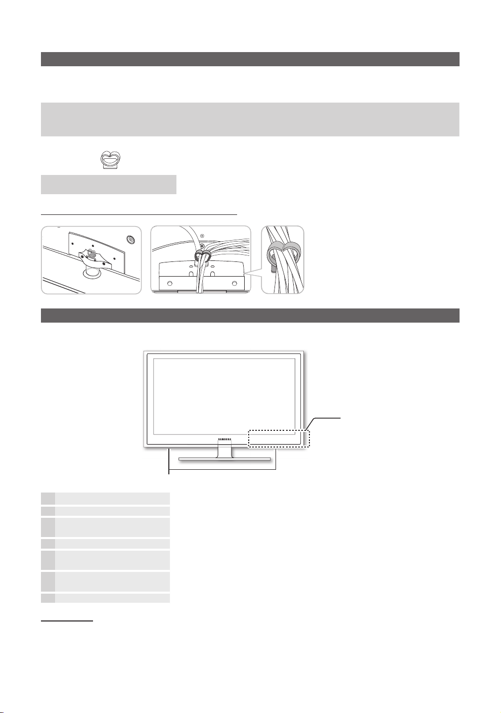
Assembling Holder-wire stand (UA40D5003 Model only)
Viewing the Control Panel
y Cleaning Cloth
y Power Cord
✎
The product colour and shape may vary depending on the model.
Control Panel
Speakers
P
(Power)
Power Indicator Blinks and turns off when the power is on and lights up in standby mode.
SOURCE
MENU Displays an on-screen menu, the OSD (on screen display), of your TV’s features.
- VOL +
z
Remote control sensor Aim the remote control towards this spot on the TV.
Standby mode
Do not leave your TV in standby mode for long periods of time (when you are away on a holiday, for example). A small amount
of electric power is still consumed even when the power button is turned off. It is best to unplug the power cord.
E
Turns the TV on or off.
Toggles between all the available input sources. In the on-screen menu, use this
button as you would use the ENTERE button on the remote control.
Adjusts the volume. In the OSD, use the - VOL + buttons as you would use the
◄ and ► buttons on the remote control.
Changes the channels. In the OSD, use the
▼ and ▲ buttons on the remote control.
z
buttons as you would use the
4
English

Viewing the Remote Control
01 Getting Started
Turns the TV on and off.
Have direct access to channels.
Alternately select Teletext ON / Double / Mix
/ OFF.
Adjusts the volume.
Displays channel list on the screen. (P. 10)
Views the Media Play. (P. 16)
Quickly selects frequently used functions.
Selects on-screen menu items and changes
menu values.
Returns to the previous menu. (P. 10)
Buttons in the Media Play menu, etc.
MEDIA.P
A B C D
HDMI
Displays and selects the available video sources.
(P. 10)
Returns to the previous channel.
Cut off the sound temporarily.
Changes channels.
Displays the main on-screen menu. (P. 10)
Selects the HDMI mode directly.
Displays information on the TV screen.
Exit the menu. (P. 10)
Installing batteries (Battery size: AAA)
SRS P.SIZE P.MODE
✎
NOTE
Use the remote control within 23 feet from the TV.
x
Bright light may affect the per formance of the remote
x
control. Avoid using nearby special fluorescent light or
neon signs.
The colour and shape may vary depending on the
x
model.
SRS : Turns the SRS TruSurround on and off. (P. 13)
P.SIZE : Choose the picture size. (P. 12)
P.MODE : Selects the Picture Mode. (P. 11)
English
5
Getting Started
HDMI
POWER
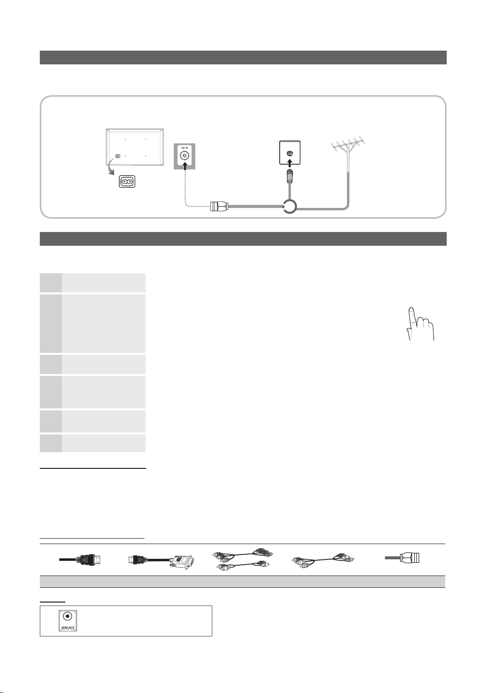
Connecting to an Antenna
When the TV is initially powered on, basic settings proceed automatically.
✎
Preset: Connecting the mains and antenna.
✎
The position of power input port may differ depending on the model.
TV Rear Panel
Cable
or
Plug & Play (Initial Setup)
When the TV is initially powered on, a sequence of on-screen prompts will assist in confi guring basic settings. Press the POWERP button.
Plug & Play is available only when the Input source is set to TV.
Selecting a language
1
Selecting Store Demo or
Home Use
2
Selecting an area.
3
Selecting a channel
4
Setting the clock
5
Enjoy your TV.
Press the ▲ or ▼ button, then press the ENTERE button.
Select the desired OSD (On Screen Display) language.
Press the ◄ or ► button, then press the ENTERE button.
y Select the Home Use mode. Store Demo Mode is for retail
environments.
y Return the unit’s settings from Store Demo to Home Use (standard):
Press the volume button on the TV. When the OSD volume is displayed,
press and hold MENU for 5 sec.
Press the ▲ or ▼ button, then press the ENTERE button.
Select the appropriate area.
Press the ENTERE button, then the channel search will start automatically.
For more information, refer to Channel → Auto Store. (P. 11)
✎
Press the ENTERE button at any time to interrupt the memorisation process.
Press the ◄ or ► button to select Month, Day, Year, Hour, Minute or am/pm.
Set these by pressing the ▲ or ▼ button.
Press the
ENTERE button.
VHF/UHF Antenna
P
6
If You Want to Reset This Feature...
Select System - Plug & Play (Initial Setup). Enter your 4 digit PIN number. The default PIN number is “0-0-0-0”. If you want to change
the PIN number, use the Change PIN function.
✎
You should do Plug & Play (MENU → System) again at home although you did in shop.
✎
If you forget the PIN code, press the remote control buttons in the following sequence in Standby mode, which resets the PIN to
“0-0-0-0”: MUTE → 8 → 2 → 4 → POWER (on).
Input Cables (Sold Separately)
Service
6
HDMI HDMI-DVI Component Composite (AV) Coaxial (RF)
Connector for service only.
English
P
R PB Y
R-AUDIO-L
P
R PB Y
R-AUDIO-L
P
R PB Y
W W
BGRRWY
Connections
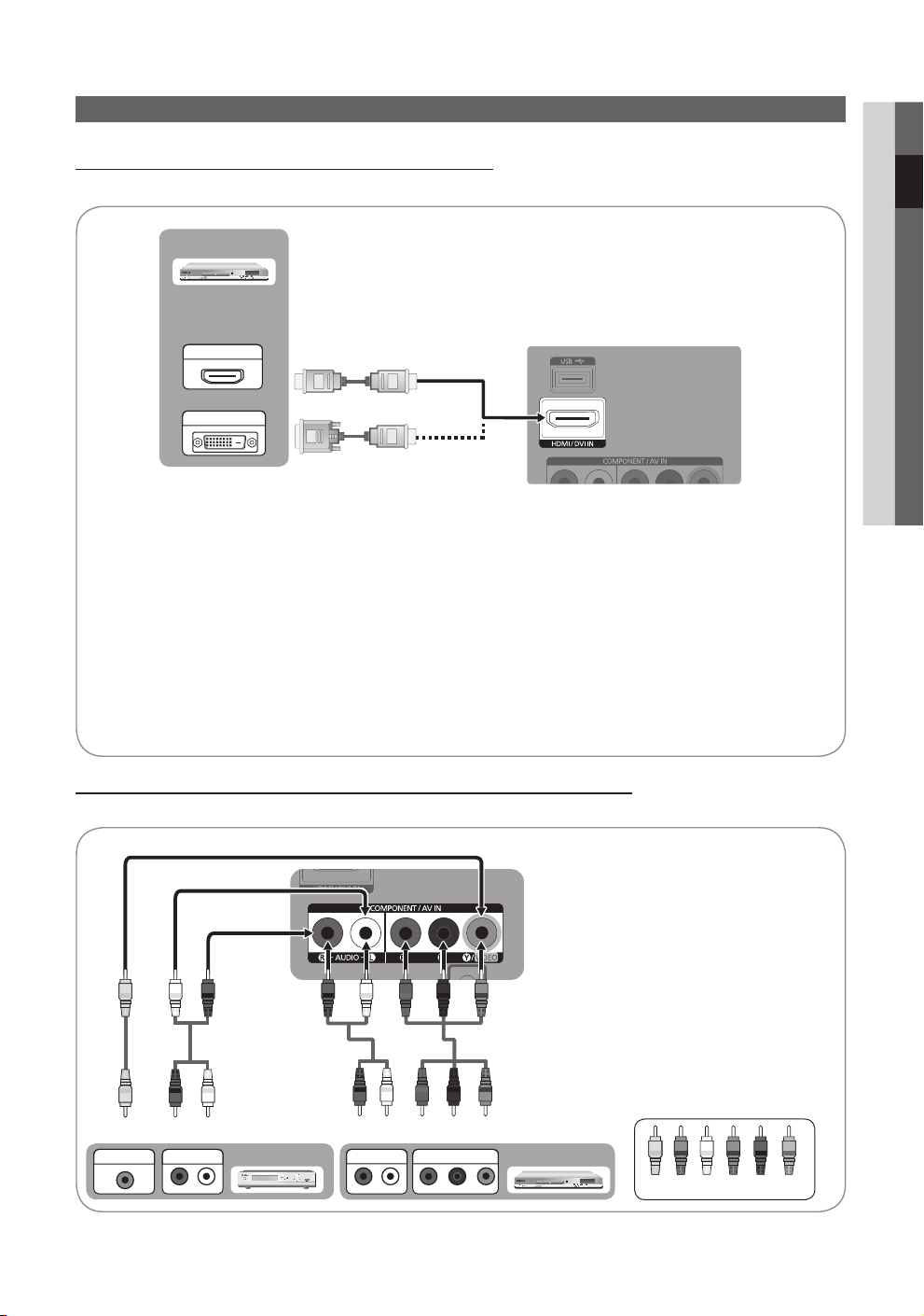
Connecting to an AV Device
Using an HDMI / DVI Cable: HD connection (up to 1080p)
Available devices: DVD / Blu-ray player / HD Cable Box / HD Satellite receiver (STB) / Cable Box / Satellite receiver (STB)
DVD
TV Rear
HDMI OUT
DVI OUT
HDMI/DVI IN
✎
For better picture and audio quality, connect to a digital device using an HDMI cable.
x
An HDMI cable supports digital video and audio signals, and does not require an audio cable.
x
– To connect the TV to a digital device that does not support HDMI output, use an HDMI/DVI and audio cables.
The picture may not display normally (if at all) or the audio may not work if an external device that uses an older
x
version of HDMI mode is connected to the TV. If such a problem occurs, ask the manufacturer of the external
device about the HDMI version and, if out of date, request an upgrade.
Be sure to purchase a certified HDMI cable. Otherwise, the picture may not display or a connection error may occur.
x
A basic high-speed HDMI cable or one with ethernet is recommended. This product does not support the
x
ethernet function via HDMI.
If an HDMI to DVI cable is connected to the HDMI IN(DVI) port, the audio does not work.
x
02 Connections
Using a Component Cable: (up to 1080p) / Using an Audio/Video: (480i only)
Available devices: VCR / DVD / Blu-ray player / Cable Box / Satellite receiver
TV Rear
✎
Y
Y
Y
B
VIDEO OUT
W
R
W
R
AUDIO OUT
VCR
WR
AUDIO OUT
BRG
G W R
B
R
COMPONENT OUT
When connecting to AV IN, the colour of
the AV IN [Y/VIDEO] jack (Green) does not
match the colour of the video cable ( Yellow).
✎
To obtain the best picture quality, the
Component connection is recommended
over the A/V connection.
Blu-ray player
Yellow Red White Red Blue Green
English
7

Connections
Using an HDMI/DVI Cable
TV Rear
Connecting to a PC
DVI OUT HDMI OUT
Display Modes (HDMI/DVI Input)
LA32D403 / UA32D4003 / UA26D4003 : Optimal resolution is 1360X768@60Hz.
Mode Resolution
IBM
MAC
VESA DMT
640 x 350 31.469 70.086 25.175 + / 720 x 400 31.469 70.087 28.322 - / +
640 x 480 35.000 66.667 30.240 - / 832 x 624 49.726 74.551 57.284 - / -
640 x 480
800 x 600
1024 x 768
1360 x 768 47.712 60.015 85.500 + / +
720 x 576 35.910 59.950 32.750 - / +
Horizontal Frequency
(KHz)
31.469 59.940 25.175 - / -
37.861 72.809 31.500 - / -
37.500 75.000 31.500 - / -
37.879 60.317 40.000 + / +
48.077 72.188 50.000 + / +
46.875 75.000 49.500 + / +
48.363 60.004 65.000 - / -
56.476 70.069 75.000 - / -
60.023 75.029 78.750 + / +
Vertical Frequency
(Hz)
Pixel Clock Frequency
(MHz)
Sync Polarity
(H / V)
8
English

Connecting to a PC
Display Modes (HDMI/DVI Input)
LA40D503 / UA40D5003 / UA22D5003 : Optimal resolution is 1920X1080@60Hz.
Mode Resolution
IBM
MAC
VESA DMT
VESA DMT / DTV
CEA
640 x 350 31.469 70.086 25.175 +/720 x 400 31.469 70.087 28.322 -/+
640 x 480 35.000 66.667 30.240 -/832 x 624 49.726 74.551 57.284 -/-
1152 x 870 68.681 75.062 100.000 -/-
640 x 480 31.469 59.940 25.175 -/640 x 480 37.861 72.809 31.500 -/640 x 480 37.500 75.000 31.500 -/800 x 600 37.879 60.317 40.000 +/+
800 x 600 48.077 72.188 50.000 +/+
800 x 600 46.875 75.000 49.500 +/+
1024 x 768 48.363 60.004 65.000 -/1024 x 768 56.476 70.069 75.000 -/1024 x 768 60.023 75.029 78.750 +/+
1152 x 864 67.500 75.000 108.000 +/+
1280 x 1024 63.981 60.020 108.000 +/+
1280 x 1024 79.976 75.025 135.000 +/+
1280 x 800 49.702 59.810 83.500 -/+
1280 x 800 62.795 74.934 106.500 -/+
1280 x 960 60.000 60.000 108.000 +/+
1360 x 768 47.712 60.015 85.500 +/+
1440 x 900 55.935 59.887 106.500 -/+
1440 x 900 70.635 74.984 136.750 -/+
1680 x 1050 65.290 59.954 146.250 -/+
1920 x 1080p 67.500 60.000 148.500 +/+
Horizontal Frequency
(KHz)
Vertical Frequency (Hz) Pixel Clock Frequency (MHz) Sync Polarity (H / V)
03 Basic Features
✎
NOTE
y For HDMI/DVI cable connection, you must use the HDMI (DVI) IN jack.
y The interlace mode is not supported.
y The set might operate abnormally if a non-standard video format is selected.
y PC(D-Sub) input is not supported.
y If an HDMI to DVI cable is connected to the HDMI IN(DVI) port, the audio does not work.
✎
Connecting through the HDMI cable may not be supported depending on the PC.
English
9
 Loading...