

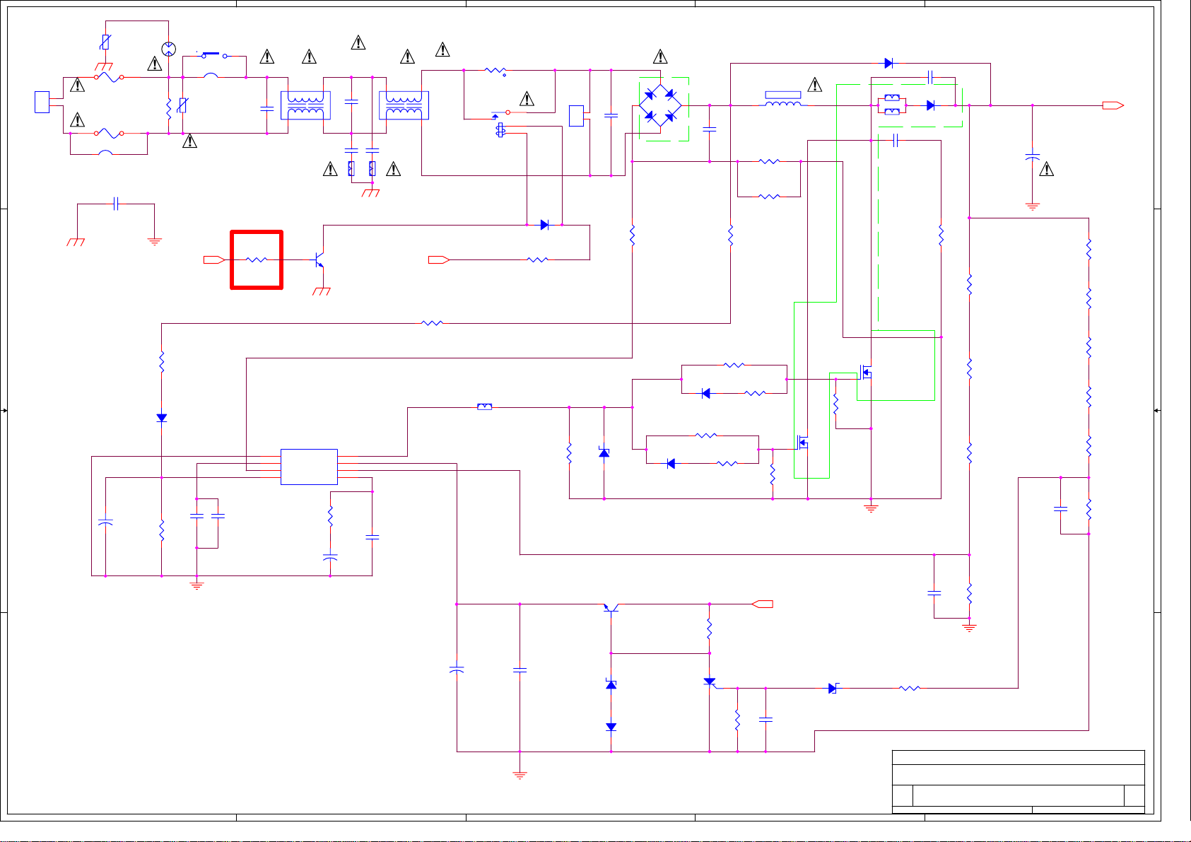
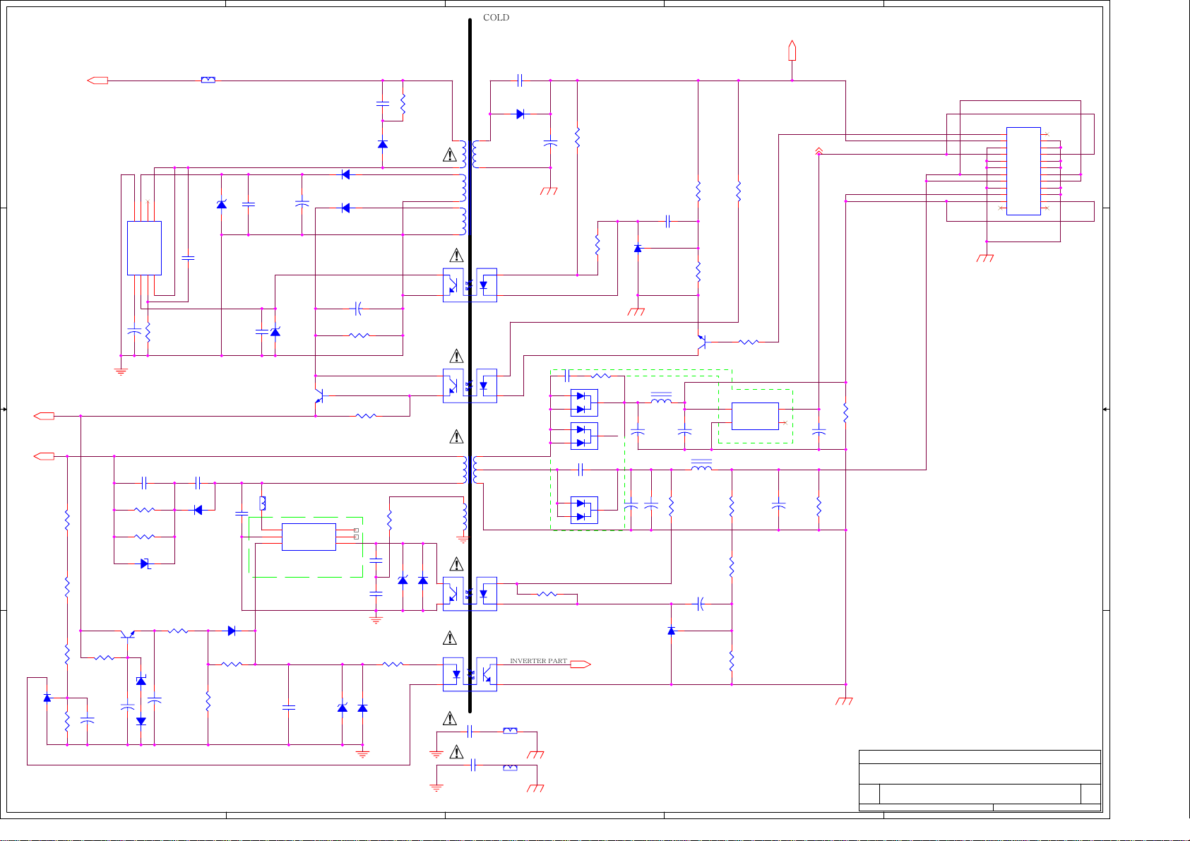
Samsung BN44-00167A Schematic
5
SX801
RX801
RA-452MS-V7
!
RP818
560KRF 3216
BAV70 (SOT-23)
CP803
SW1NC
1 2
J812,J811
1 2
JUMPER 15mm
VX801
14N751
!
ON/OFF
DP806
NC
CX801
0.68uF275V
RS813
1KRF 2012
CP813
MY/50V/102/J
!
1
2
3
4
LX801
CV940120S
1
4
400VAC 471M
2
ICP801
GND
ICOM
ISEN
VIN
ICE1PCS02
RP807
10KRF 2012
CP804
50V 1uF
VX802
14N751
!
FS801
T6.3AH250V
1
L
2
N
D D
PD801S
YW396-03AB
C C
B B
!
FS802
1 2
J813,J814
JUMPER 15mm
MSR 1/2W 560KR
NC
CY813
NC
+
CP802
50V 0.22uF
RP806
47KRF 3216
!
CY821
GATE
VCC
VSEN
VCOM
23
!
31
QS803
KTN2222
CX803
0.47uF275V
LING BEAD
8
7
6
5
+
4
!
!
LX802
CV940120S
1
4
CY822
400VAC 471M
LING BEAD
!
560KRF 3216
CP805
334K 2012
23
STB 6.5V
RP802
3
!
NT801
5D15
1 2
t
REL801
10A250V
3
BP802
3550
4
1
2
!
DS805
1N4937
RS814
JUMPER
RP808
100KRF 2012
1
L
2
N
CN811
YW396-03AV
ZDP801
24V(SOT-323)
CX802
0.47uF275V
!
BD801
GSIB15A60
3
HS801
2
DP805
100*9*23
1
CX804
0.1uF275V
DP804
BAV70(SOT-323)
RP809
100RF 2012
-+
4
RP804
220RF 2012
BAV70(SOT-323)
RP810
100RF 2012
RP825
10RF 2012
RP801
MPR5W 0.1R
RP803
RP819
560KRF 3216
RP826
10RF 2012
10KRF 2012
NC
RP812
LP801
EER4042
1
2
!
HS802
100*20*30
23
QP802
FQA13N50CF
BP803
3550
BP804
3550
1
MUR460L
23
DP801
QP801
FQA13N50CF
RP811
10KRF 2012
CP810
NC
DP802
YG963S6R,LSL9R860PF2
CP801
1KV 101K
RP805
2W 47R
CP809
450V220uF(35*30)
RP817
560KRF 3216
RP816
560KRF 3216
RP815
560KRF 3216
1
+
!
CP811
104K 2012
PFC 385V
RP820
330KRF 2012
RP821
330KRF 2012
RP822
330KRF 2012
RP823
330KRF 2012
RP824
220KRF 2012
RP828
22KRF 2012
QP803
C1008-Y TO-92
1
3
2
CP806
+
50V 47uF
A A
5
4
CP807
104K 2012
ZDP807
ZN16B(AXIAL)
DP807
BAV70(SOT-323)
3
SCP801
MCR100-6
RP813
3.3KRF 2012
RP829
100KRF 2012
VCC PFC
CP812
104K 2012
ZDP803
6.2V(AXIAL)
2
CP808
222K 2012
RP827
0RJ 2012
Thursday, July 12, 2007
Title
PFC
Size Document Number Rev
<Doc>
A3
Date: Sheet
22KRF 2012
2006. 06.07
RP814
12
1
of
5
4
HOT
COL
D
3
2
STB5.2V
1
RM820
100R 1W
ZDM801
CM804
50V 47uF
CS810
1KV 10pF
CM802
1KV 101K
DM801
UF4007
BP801
3550
ZDS801
24V(SOT-323)
1 2
DM810
1N4148(AXIAL)
RM821
75RF 2012
RM802
47KRF 2012
CS805
472K 2012
CM818
1KV 68pF
CS802
50V 10uF
CS808
104K 2012
1 2
BM801
3550
1
2
3 4
FSDM0565REWDTU
ICM801
CM815
104K 2012
+
ZDS802
15V(AXIAL)
QS801
C2331
TO-92
HS803
40*20*30
DRAIN
GND
VCC FB
ZDM805
24V(AXIAL)
NC
SS
CS801
1KV 471K
DS801
UF4007
DS802
1N4937
DS803
1N4937
CS804
50V 47uF
RS804
47KRF 2012
100KRF 2012
6
5
CM803
104K 2012
CM816
223K 2012
1 2
4
+
RS805
15V(SOT-323)
RM819
3.9KRF 2012
DM809
NC
RM818
3KRF 3216
ZDM802
2W 220KR
1 2
RS801
TM801
EER2828
DM808
SS26
1
!
2
5
7
6
7
!
4
!
TCED1108
4
!
7 14
5 8,9,10
3
2
!
4
!
1
2 3
!
CY811
400VAC 471M
!
CY812
400VAC 152M
PFC385V
D D
876
5
D2
N.C
VCC
CS803
50V 1uF
QM801
C1008-Y
TO-92
3
CM805
50V 10uF
123
CM801
1KV 222K
RM801
2W 100KR
RM804
2W 100KR
TDM801
P6KE160A
2
+
DM802
1N4148(AXIAL)
5
GND2
SSFBCS
D1
4
+
RS803
SR37 1W 2.2R
1
16V(AXIAL)
+
ICS801
ICE3B0365J
C C
PFC VCC
PFC 385V
B B
RM817
560KRF 3216
RM816
1MRF 3216
RM815
1MRF 3216
A A
ICM804
KA431
20KRF 2012
2 3
RM814
RM803
2.2KRF 2012
1
+
CM814
50V 47uF
9
11
TS801
EE2020
PCS801
TCED1108
PCS802
11,12,13
L1
INDUCTOR
PCM801
TCED1108
PCI801
TCED1108
LING BEAD
CS809
1KV 101K
DS804
SB2100
CS806
10V1000uF
1
23
1
23
HS804
80*15*30
MBRF10H100CT
1
23
INVERTER PART
4
BM803
3550
+
CM806
1KV 102K
DM804
RM806
3.3KRF 2012
3
RS806
220RF 2012
DM805
1
3
NC
1
3
DM803
MBRF10H150CT
CM810
1KV 221K
1
3
RS807
4.7KRF 2012
RM812
2W 12R
2
2
2
CM811
10V 1000uF
UVLO
RS808
2.2KRF 2012
CS807
63V 104
1
ICS802
2 3
KA431
KTN2222AS (CHIP)
LM802
4.7uH
+
CM807
25V 1000uF(12.5*25)
+
+
CM817
10V 1000uF
ICM803
KA431
QS802
RM805
330RF 2012
1
2 3
1
3
+
CM808
25V 1000uF
LM801
4.7uH
+
RS810
2KRF 2012
RS812
2
4.7KRF 2012
1 2
IN OUT
3 4
GND CTR
KIA278R12
RM807
2KF 2012
RM808
330RF 2012
CM813
50V 0.22uF
RM809
2KRF 2012
RS811
1KRF 2012
ICM802
25V 220uF
+
CM812
10V 1000uF
2
STB 5.2V 0.4A
12V D
+
CM809
POWER ON/OFF
AUDIO 12V/ 1.2A
Main_5.4V/4.0A
SYSTEM_13V/2.0A
RM811
1W 2.2KR
RM810
2W 220R
Thursday, July 12, 2007
SIP400B
Title
STB+MULTI
Size Document Number Rev
Date: Sheet
Custom
<Doc>
CN801
12
34
56
78
910
11 12
13 14
15 16
17 18
19 20
21 22
23 24
SMW200-24C
1
22
of

12VDC
ON/OFF
VDDA
UVLO
PWM
CI844
47u/50V/AL
12Vdc
+
RI891
100R/F
PWM
RI802 120KR/F
RI801 120KR/F
RI841 10KR/F
CI803
0.1u/50V
RI815
10KR/F
CI838
1u/25V
1u/25V
CI843
RI803
27KR/F
RI892
10KR/F
KTN2222AS
QI810
RI808
24KR/F
RI862 1KR/F
RI865 1KR/F
RI853
100R/F
QI815
KTN2222AS
RI848
100R/F
ICI801 LX1691A
1
GND
2
AOUT
3
BOUT
4
DD_CLK
5
DIM_MODE
6
BRITE_OUT
7
BRITE_R
8 9
BRITE_IN ENABLE
RI804
20KR/F
RI852
10KR/F
1
QI805
DTC144EKA
CI809
0.1u/50V
QI813
KTN2222AS
QI814
KTN2907AS
RI842
10KR/F
PFC385V
DI809
!
BAV70
DI814
CI823
NC
RI830
4.7KR/F
RI819
1KR/F
DI804
BAV70
RI863
1KR/F
RI836
0R/J
RI864
5.6KR/F
DI808
BAV70
CI830
NC
NC
DI812
RI846
120R/F
NC
RI824
1.5KR/F
RI845
120R/F
QI807
KTN2907AS
RI823
1KR/F
2
RI811
NC
CI808
CI833
1u/25V
5
QI812
KTN2222AS
QI811
KTN2907AS
5V
VDDA
CI834
1u/25V
CI802
0.1u/50V
CI807
CI811
22n/50V
1u/25V
RI866
220KR/F
RI860
220KR/F
VR801
15KR/20%
CI835
1u/25V
RI832
1M/F
RI847
QI806
470KR/F
KTN2222AS
RI838 1KR/F QI801
RI839 1KR/F
RI818
100R/F
QI816
KTN2222AS
16
VDDP
15
VDDA
14
OP_SNS
13
VIN_SNS
12
I_SNS
11
EA_OUT
10
I_R
RI810
NC
RI812
10KR/F
RI813
10KR/F
QI804
2
3
1u/25V
2
3
1
DTC144EKA
10
9
7
8
TI802
FULSE TRANS MAIN TRANS
EE1614
RI816
NC
QI803
KTN2222AS
RI851
1M/F
DI811
BAV70
QI809
KTN2907AS
RI856
33KR/F
1
RI858
470KR/F
A
ICI803A
KIA358
FI801
250Vac/T3.15A
RI806
4R7/F
RI844
10KR/F
RI817
4R7/F
RI840
10KR/F
84
+
-
3.3n/50V
3
2
CI828
ZDI802
CI840
ZN15V
4.7n/50V
ZDI803
ZN15V
CI826 NC
RI887 44R/G/(2W MOR)
RI888 44R/G/(2W MOR)
CI837
CI832
NC
NC
CI827
1n/50V/J
DI801
MUR460L
FQPF13N50C
DI810
MUR460L
CI839
4.7n/50V
RI857
100KR/F
DI807
BAV70
1
1
QI802
FQPF13N50C
CI829
1u/25V
!
3
DI813
31GF6
2
2
DI802
31GF6
3
CI806
1u/400V/MP
2
TI801
UU32.5
-
6
7
+
8 4
CI814
2.2uF/10V
5
0.1u/50V
CI815
ICI802B
KIA358
RI826
470KR/F
RI820
1M/F
RI849
1M/F
RI827
1M/F
RI867 150R/F/3216
RI869 150R/F/3216
RI868 150R/F/3216
61
RI871 150R/F/3216
RI873 150R/F/3216
RI872 150R/F/3216
RI874 150R/F/3216
RI870 150R/F/3216
5
4
RI882 150R/F/3216
RI875 150R/F/3216
RI881 150R/F/3216
RI880 150R/F/3216
3
RI876 150R/F/3216
RI877 150R/F/3216
RI879 150R/F/3216
RI878 150R/F/3216
CI842
0.1u/50V
RI837
10KR/F
RI854
100KR/F
CI819
3.3n/50V
CI822
3.3n/50V
CI824
27p/6kV(10mm)
CI813
2.2n/50V
CI825
2.2n/50V
CI820
27p/6kV(10mm)
5V
84
1
RI809
0R/J
RI814
0R/J
ICI802A
KIA358
3
+
2
-
CI816
0.1u/50V
RI843
NC
RI861
NC
1
PR_2
FB
LD
PR_3
PR_2
PR_3
PR_2
2
CNI801
35002WS-02L
CNI802
1
2
35002WS-02L
PR_2
PR_3
PR_2
PR_2
FB
LD
PR_3
RI834
RI833
100KR/F
5.6KR/F
DI805
BAV99
BAV70DI806
DI803
BAV99
RI829
1M/F
RI805
NC
RI825
1M/F
CI818
1u/25V
CI821
1u/25V
RI828
1M/F
CI817
0.1u/50V
CI845
1n/50V
RI835
100KR/F
RI831
5.6KR/F
5V
QI808
5V
RI822
100KR/F
RI855
180KR/F
RI859
56KR/F
6
5
ICI803B
KIA358
-
+
ZDI805
N6.2V
8 4
KTC4375
213
RI807
4.7KR/F
CI804
ZDI801
1u/25V
ZN5.6V
7
RI850
0R/J
PWM
A
RI821
30KR/F
RI890
27KR/F
DIM
CI831
1u/25V
12Vdc
12VDC
ON/OFF
12VDC
DIM
FB
LD
CI812
1u/25V
1
2
3
4
5
1
2
3
4
5
CNI803
SMW200-05
CNI806
SMW200-05
Inverter On/Off
Dim
NC
GND
DET_5V
VCC_12V
FB
GND
NC
LD
SIP400B REV1.1 (R.C)
Title
Size Document Number Rev
Custom
Date: Sheet
11Tuesday, March 27, 2007
0.2
of
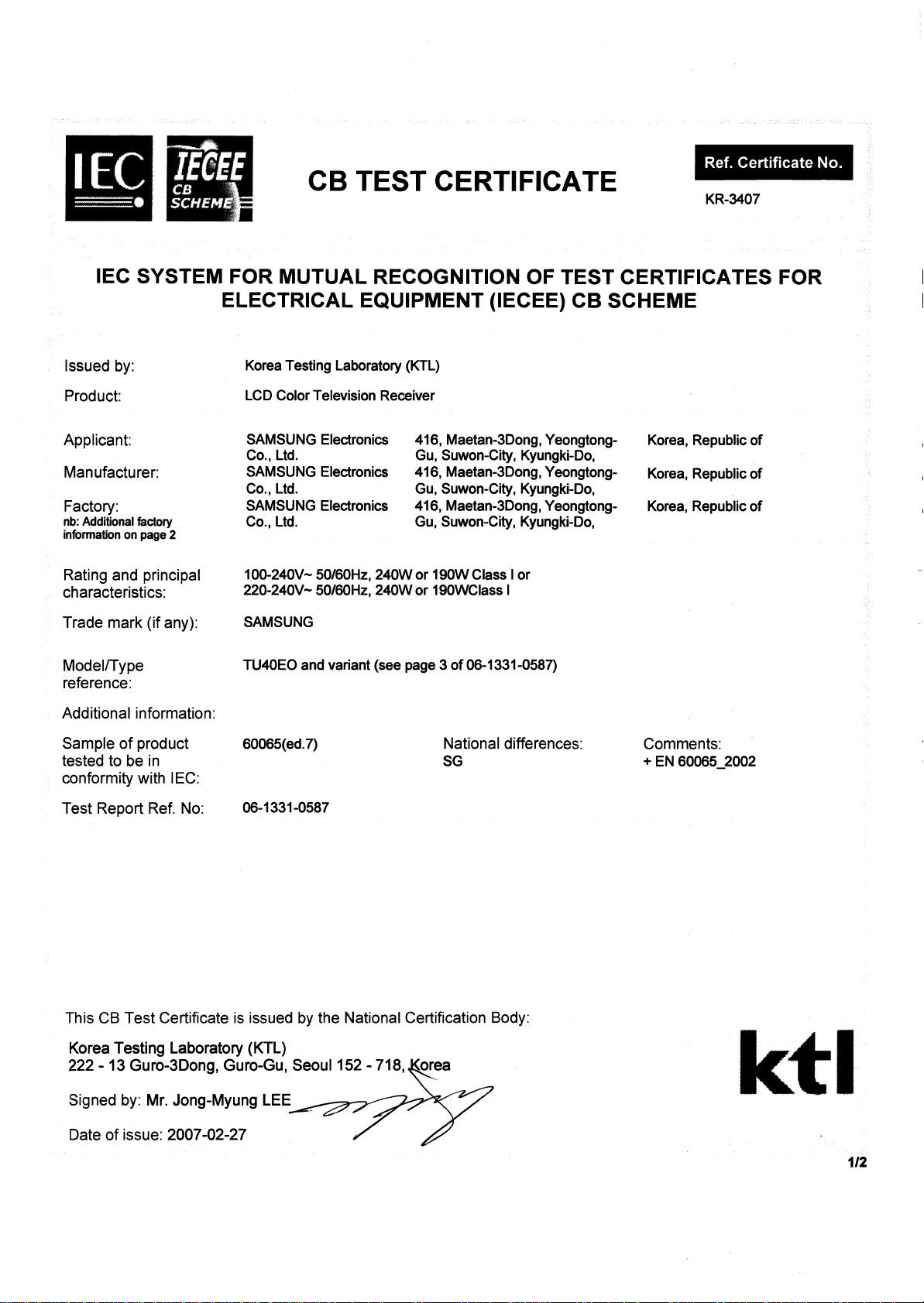
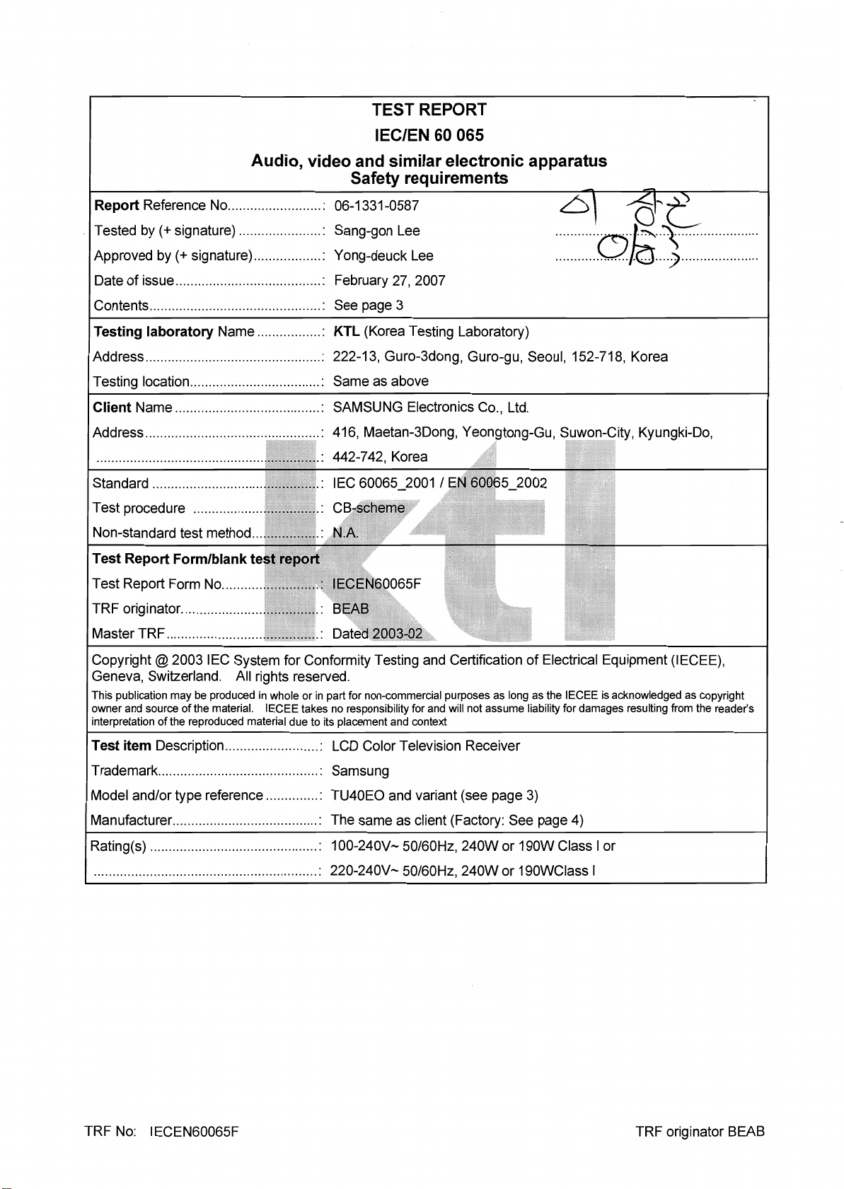
CB TEST CERTIFICATE
KR-3407
IEC SYSTEM FOR MUTUAL RECOGNITION OF TEST CERTIFICATES FOR
ELECTRICAL EQUIPMENT (IECEE) CB SCHEME
Issued by:
Product:
Applicant:
Manufacturer:
Factory:
nb: Additional factory
information on
page
2
Rating and principal
characteristics:
Trade mark (if any):
Modelrrype
reference:
Additional information:
Sample of product
tested to be in
conformity with IEC:
Test Report Ref. No:
Korea Testing Laboratory (KTL)
LCD Color Television Receiver
SAMSUNG Electronics 416, Maetan3Dong, Yeongtong- Korea, Republic of
Co., Ltd. Gu, Suwon-City, Kyungki-Do,
SAMSUNG Electronics 416, Maetan3Dong. Yeongtong- Korea, Republic of
Co., Ltd. Gu, Suwon-Ci, Kyungki-Do,
SAMSUNG Electronics 416, Maetan3Dong, Yeongtong- Korea, Republic of
Co., Ltd. Gu, Suwon-City, Kyungki-Do,
100-240V- 50160Hz. 240W or 190W Class I or
220-240V- 50160Hz. 240W or 19OWClass
SAMSUNG
TU4OEO and variant (see page 3 of 06-1331-0587)
60065(ed.7)
06-1331-0587
National differences: Comments:
SG
I
+
EN 60065-2002
This CB Test Certificate is issued by the National Certification Body:
Korea Testing Laboratory (KTL)
222
-
13 Guro-3Dong, Guro-Gu, Seoul
152 - 718,
orea
&.
Signed by: Mr. Jong-Myung LEE
Date of issue:
2007-02-27

Page 2 of 48 Ref. No. : 06-1331-0587
Test case verdicts
Test case does not apply to the test object.................. : N(.A.)
Test item does meet the requirement .......................... : P(ass)
Test item does not meet the requirement .................... : F(ail)
Testing
Date of receipt of test item .......................................... :
Date(s) of performance of test………………………:
December 12, 2006
December 12, 2006 – February 26, 2007
General remarks
This report is not valid as a CB Test Report unless signed by an approved CB Testing Laboratory and
appended to a CB Test Certificate issued by a NCB, in accordance with IECEE 02.
This report shall not be reproduced except in full without the written approval of the testing laboratory.
The test results presented in this report relate only to the item(s) tested.
"(see appended table)" refers to a table appended to the report.
“(see remark #)” refers to a remark appended to the report.
“(see Annex #) refers to an annex appended to the report.
Throughout this report a comma (point) is used as the decimal separator.
Summary of Testing and Conclusions
The sample(s) tested complies with the requirements of IEC/EN 60065:2002. Compliance with European
Special National Conditions, Annex ZB, and A – Deviations, Annex ZC, is recorded at the end of this report.
TRF No: IECEN60065F TRF originator BEAB

Page 3 of 48 Ref. No. : 06-1331-0587
Items covered
1. Model number covered by the scope of this test report is as follows;
The products differences in the following respects: Minor differences in the external design as well as in
the low voltage secondary circuits, with no importance from safety point of view.
As the differences from TU40EO, listed below.
Alternative models type : xx40yy or
1)2) 3)4) 5)6) 7)8)9)10)11) 5)6) 7)8)9)10)11)
xx40yyyyy
or
xx-40yyyyy
Models designation can be explaned by follows.
40: Screen size
1)2)
: Project name (can be TU,BP,JA, BD)
3)4)
: Marketing region (can be EO, UO, SO, JO, KO, CO)
5)6)
: Marketing region (can be LN, LT, LTN, LS, LTP, LW, LNR, LE, LA, SE)
7)
: Cabinet design for project (can be M, R, S)
8)9)
: Cabinet design (can be any 2 numeric characters)
10)11)
: Function (can be any 2, 3, 4 or 5 alphanumeric characters or blank)
2. We tested TU40EO as a basic model for the most severe test conditions.
3. These products, TU40EO series, are intended to use of internal SMPS power boards as follows.
1) Model no. of internal SMPS power board: IP-231135A
- Manufacturer: Samsung Electro-Mechanics Co., Ltd.
- Rating: 100-240Vac, 50/60Hz, 4.0A Cl.l
- Output: 0.5A/ +5.2V, 4.0A/+5.4V, 1.2A/+12.0V, 2.0A/+13.0V, (CNI801-CNI802) 100mA/2100Vac
- Applied Standard: IEC 60065:2001 / EN 60065:2002
- Approved by: NEMKO AS
- Report and Certification No. : 78822 / NO41914
2) Model No. of internal SMPS power board: SIP400B
- Manufacturer: Hansol LCD Inc.
- Rating: 100-240Vac, 50/60Hz, 4.0A Cl.l
- Output: STB DC 5.2Vdc/0.3A, DC 5.4V/3.5A, DC 12V/1.0A, DC 13V/1.5A,
Inverter 1500Vrms/72mArms
- Applied Standard: IEC 60065:2001 / EN 60065:2002
- Approved by: DEMKO
- Report and Certification No. : E301536-C06T003-1 / DK-10597
4. These models, TU40EO series, have two input rated voltage according to marketing area. There is no
difference except for marking of rated voltage.
5. Marking of power consumption might be different according to adopted LCD panel.
- The model series with marking of 240W power consumption: xx40TU, xx40yyMyy or xx-40yyMyy
- The model series with marking of 190W power consumption: Others models
TRF No: IECEN60065F TRF originator BEAB
Page 4 of 48 Ref. No. : 06-1331-0587
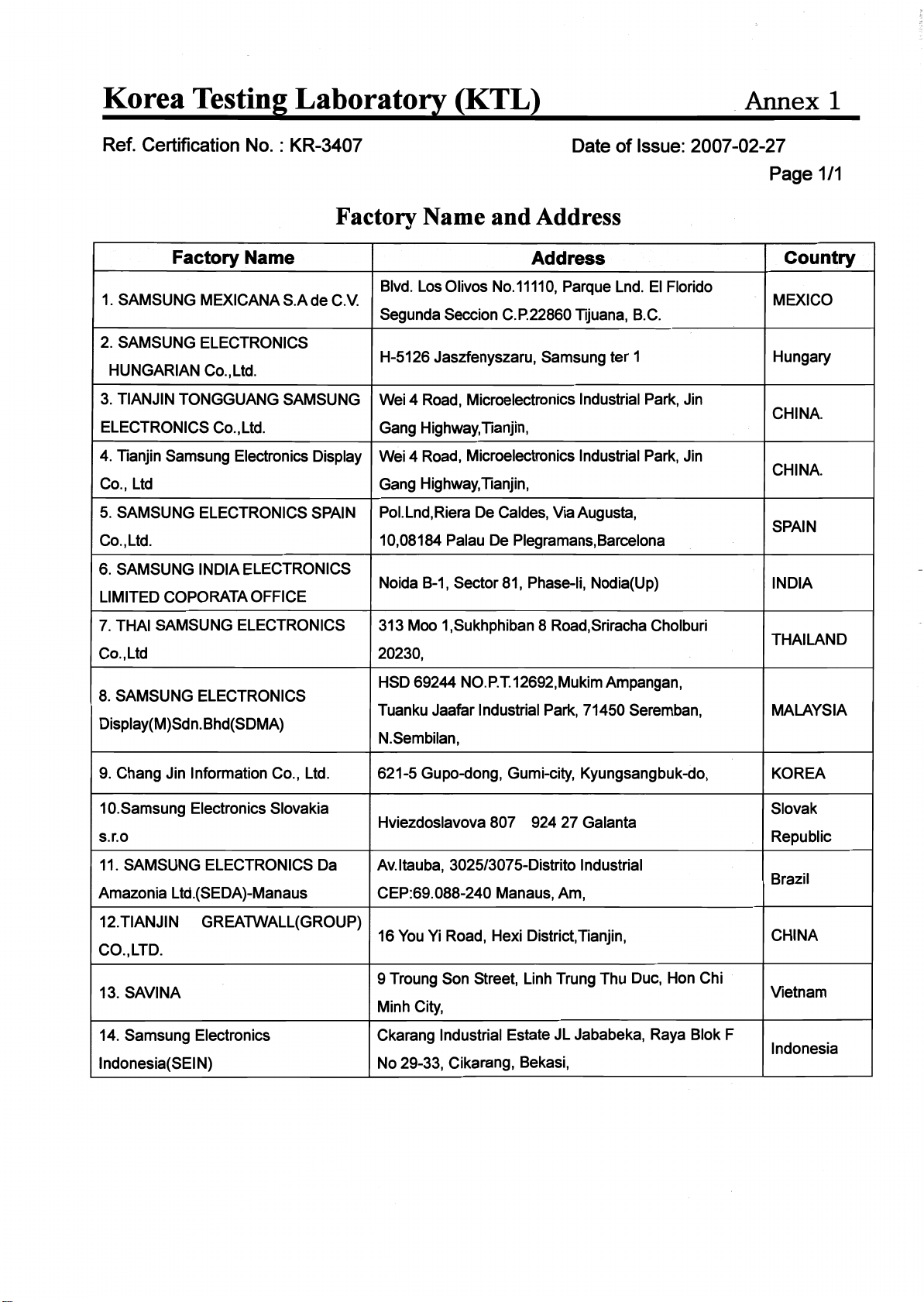
Manufacturer and factory
1. The same as manufacturer
2. SAMSUNG MEXICANA S.A de C.V.
Blvd. Los Olivos No.11110, Parque Lnd. El Florido
Segunda Seccion C.P.22860 Tijuana, B.C.MEXICO.
3. SAMSUNG ELECTRONICS HUNGARIAN Co., Ltd.
H-5126 Jaszfenyszaru, Samsung ter 1 Hungary.
4. TIANJIN TONGGUANG SAMSUNG ELECTRONICS Co., Ltd.
Wei 4 Road, Microelectronics Industrial Park, Jin
Gang Highway,Tianjin, People’s Republic Of CHINA.
5. Tianjin Samsung Electronics Display Co., Ltd
Wei 4 Road, Microelectronics Industrial Park, Jin
Gang Highway,Tianjin, People’s Republic Of CHINA
6. SAMSUNG ELECTRONICS SPAIN Co., Ltd.
Pol.Lnd,Riera De Caldes, Via Augusta,
10,08184 Palau De Plegramans,Barcelona,SPAIN.
7. SAMSUNG INDIA ELECTRONICS LIMITED COPORATA OFFICE
Noida B-1, Sector 81, Phase-Ii, Nodia(Up) INDIA.
8. THAI SAMSUNG ELECTRONICS Co., Ltd.
313 Moo 1,Sukhphiban 8 Road,Sriracha Cholburi 20230,THAILAND..
9. SAMSUNG ELECTRONICS Display(M)Sdn.Bhd(SDMA)
HSD 69244 NO.P.T.12692,Mukim Ampangan,
Tuanku Jaafar Industrial Park, 71450 Seremban, N.Sembilan, Malaysia
10. Chang Jin Information Co., Ltd.
621-5 Gupo-dong, Gumi-city, Kyungsangbuk-do, Korea.
11. Samsung Electronics Slovakia s.r.o
Hviezdoslavova 807
924 27 Galanta,Slovak Republic.
12. SAMSUNG ELECTRONICS Da Amazonia Ltd.(SEDA)-Manaus
Av.Itauba, 3025/3075-Distrito Industrial
CEP:69.088-240 Manaus, Am, Brazil
13. TIANJIN GREATWALL(GROUP) CO., LTD.
16 You Yi Road, Hexi District,Tianjin, China.
14. SAVINA
9 Troung Son Street, Linh Trung Thu Duc, Hon Chi Minh City, Vietnam
15. Samsung Electronics Indonesia(SEIN)
Ckarang Industrial Estate JL Jababeka, Raya Blok F No 29-33, Cikarang, Bekasi, Indonesia
Contents
1. Test report :page 1 to 45
2. EN60065:1998 Annex ZB+ZC: Page 46 and 47 of 48
3. National deviation for Singapore: Page 48 of 48
4. ATTACHMENT 1 : Photo
5. ATTACHEMNT 2 : Circuit diagrams
TRF No: IECEN60065F TRF originator BEAB
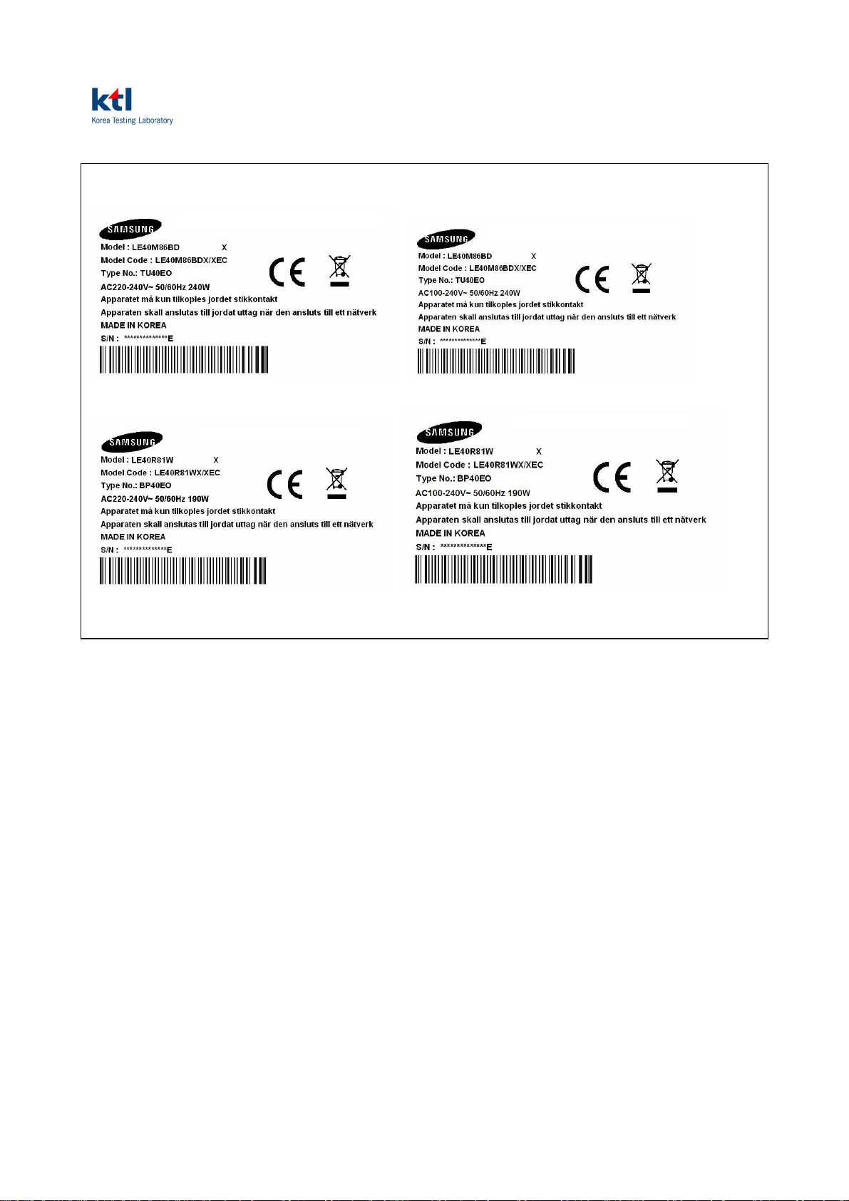
Copy of marking plate
Page 5 of 48 Ref. No. : 06-1331-0587
TRF No: IECEN60065F TRF originator BEAB
Page 6 of 48 Ref. No. : 06-1331-0587
IEC / EN 60065
Clause Requirement – Test Result - Remark Verdict
3 GENERAL REQUIREMENTS
Safety class of the apparatus ................................. : Class 1 P
4 GENERAL CONDITIONS OF TESTS
4.1.4 Ventilation instructions require the use of the test
No N
box
5 MARKING
Comprehensible and easily discernible Rear Enclosure P
Permanent durability against water and petroleum
P
spirit
5.1 Identification, maker, model ................................... : Samsung TU40EO P
Class II symbol if applicable Class l Equipment P
Rated supply voltage and symbol .......................... : AC 100-240V~ or
AC 220- 240V~
Frequency if safety dependant 50/60Hz P
Rated current or power consumption .................... : 240W or 190W P
5.2 Earth terminal Mains inlet with earth terminal P
Hazardous live terminals No live terminal N
Supply output terminals (other than mains) No supply output N
5.3 Use of triangle with exclamation mark In circuit diagram P
P
5.4 Instructions for use By English P
5.4.1 Mains powered equipment not exposed to dripping
or splashing. Warning concerning objects filled
with liquid, etc.
In user’s manual
“Do not place a water
containing vessel on this
P
apparatus, as this can result in
a risk or fire or electric shock.
Do not expose this apparatus
to rain or place it near water
(near a bathtub, washbowl,
kitchen sink or laundry tub, in a
wet basement, or near a
swimming pool etc.)
Hazardous live terminals, instructions for wiring No live terminal N
Instructions for replacing lithium battery No battery N
Instructions for modem if fitted No modem used N
TRF No: IECEN60065F TRF originator BEAB
Page 7 of 48 Ref. No. : 06-1331-0587
IEC / EN 60065
Clause Requirement – Test Result - Remark Verdict
Class I earth connection warning In user’s manual
P
“Use only a properly grounded
plug ad receptacle. An
improper ground may cause
electric shock or equipment
damage.”
Instructions for multimedia system connection In user’s manual P
Special stability warning for fixed installation The apparatus is tested to the
N
stability requirements of 19.1-3
5.4.2 Disconnect device: plug/coupler or all-pole mains
switch location, accessibility and markings
In user’s manual
“To disconnect the apparatus
P
from the mains, the plug must
be pulled out from the mains
socket, therefore the mains
plug shall be readily operable”
Instructions for permanently connected equipment No permanently connected
N
equipment
6 HAZARDOUS RADIATION
6.1 Ionizing radiation < 36 pA/kg (0,5 mR/h) No ionizing radiation N
6.1
EN 60065
European Council Directive 96/29/Euratom of 13
May 1996 10cm from outer surface of apparatus
N
<1µSv/h (0,1mR/h)
6.2 Laser radiation, emission limits to IEC 60825-1 .... : No laser system N
Emission limits under fault conditions .................... : N
7 HEATING UNDER NORMAL OPERATING CONDITIONS
7.1 Temperature rises not exceeding specified values,
(see appended table) P
no operation of fuse links
7.1.1 Temperature rise of accessible parts (see appended table) P
7.1.2 Temperature rise of parts providing electrical
(see appended table) P
insulation
7.1.3 Temperature rise of parts acting as a support or as
(see appended table) P
a mechanical barrier
7.1.4 Temperature rise of windings (see appended table) P
7.1.5 Parts not subject to a limit under 7.1.1 to 7.1.4 (see appended table) P
7.2 Softening temperature of insulating material
supporting parts conductively connected to the
mains carrying a current > 0,2 A at least 150
o
(see appended table) N
C
TRF No: IECEN60065F TRF originator BEAB
Page 8 of 48 Ref. No. : 06-1331-0587
IEC / EN 60065
Clause Requirement – Test Result - Remark Verdict
8 CONSTRUCTIONAL REQUIREMENTS WITH REGARD TO THE PROTECTION
AGAINST ELECTRIC SHOCK
8.1 Conductive parts covered by lacquer, paper,
Considered as bare P
untreated textile oxide films and beads etc.
considered to be bare
8.2 No shock hazard when changing voltage setting
No voltage setting device N
device, fuse-links or handling drawers etc.
8.3 Insulation of hazardous live parts not provided by
No hygroscopic materials N
hygroscopic material
8.4 No risk of electric shock following the removal of a
No shock hazard P
cover which can be removed by hand
8.5 Class I equipment P
Basic insulation between hazardous live parts and
P
earthed accessible parts
Resistors bridging basic insulation complying with
P
14.2.1 a)
8.6 Class II equipment and Class II constructions
within Class I equipment
Class ll construction within
class l equipment
P
(Evaluated by CB test report of
SMPS board)
Reinforced or double insulation between
hazardous live parts and accessible parts
(Evaluated by CB test report of
SMPS board)
P
Components bridging reinforced or double
insulation complying with 14.1 a) or 14.3
Basic and supplementary insulation each being
bridged by a capacitor complying with 14.2.1 a)
Reinforced or double insulation being bridged with
(Evaluated by CB test report of
P
SMPS board)
(Evaluated by CB test report of
P
SMPS board)
N
2 capacitors in series complying with 14.2.1 a)
Reinforced or double insulation being bridged with
a single capacitor complying with 14.2.1 b)
Basic insulation bridged by components complying
(Evaluated by CB test report of
P
SMPS board)
N
with 14.3.4.3
8.7 Basic insulation between parts at 35 V to 71 V
N
(peak) a.c. or 60 V to 120 V d.c. and accessible
parts
Reinforced or double insulation between circuits
N
operating at voltages between 35 V and 71 V
(peak) a.c. or between 60 V and 120 V d.c. and
hazardous live parts at higher voltage
Separation by Class II isolating transformer N
Separation by Class I transformer N
Separation by earthed conductive part N
TRF No: IECEN60065F TRF originator BEAB
Page 9 of 48 Ref. No. : 06-1331-0587
IEC / EN 60065
Clause Requirement – Test Result - Remark Verdict
8.8 Basic or supplementary insulation > 0,4 mm (mm)
P
................................................................................. :
Reinforced insulation > 0,4 mm (mm) ................... : (Evaluated by CB test report of
P
SMPS board)
Thin sheet insulation (Evaluated by CB test report of
P
SMPS board)
Basic or supplementary insulation, at least two
N
layers, each meeting 10.3
Basic or supplementary insulation, three layers
N
any two of which meet 10.3
Reinforced insulation, two layers each of which
N
meet 10.3
Reinforced insulation, three layers any two which
N
meet 10.3
8.9 Adequate insulation between internal hazardous
live conductors and accessible parts
Adequate insulation between internal hazardous
Provided double or reinforce
P
insulation
Dressed away from live parts P
live parts and conductors connected to accessible
parts
8.10 Double insulation between conductors connected
Class l equipment N
to the mains and accessible parts
8.11 Detaching of wires P
No undue reduction of creepages or clearance
Yes P
distances if wires become detached
Vibration test carried out ........................................ : No N
8.12 Adequate cross-sectional area of internal wiring to
No socket outlets N
mains socket-outlets
8.13 Adequate fastening of windows, lenses, lamp
N
covers etc. (pull test 20 N for 10 s)
8.14 Adequate fastening of covers (pull test 50 N for
N
10 s)
8.15 No risk of damage to the insulation of internal
wiring due to hot parts or sharp edges
Wires are dressed away from
hot parts or sharp edge
P
8.16 Only special supply equipment can be used No special supply equipment N
8.17 Insulated winding wire without additional
interleaved insulation
(Evaluated by CB test report of
SMPS board)
P
8.18 Endurance test as required by 8.17 N
8.19 Disconnection from the mains P
8.19.1 Disconnect device Type : Mains Plug P
All-pole switch or circuit breaker with >3mm
N
contact separation
TRF No: IECEN60065F TRF originator BEAB

Page 10 of 48 Ref. No. : 06-1331-0587
IEC / EN 60065
Clause Requirement – Test Result - Remark Verdict
8.19.2 Mains switch ON indication N
8.20 Switch not fitted in the mains cord No switch N
8.21 Bridging components comply with clause 14 N
TRF No: IECEN60065F TRF originator BEAB
Page 11 of 48 Ref. No. : 06-1331-0587
IEC / EN 60065
Clause Requirement – Test Result - Remark Verdict
9 ELECTRIC SHOCK HAZARD UNDER NORMAL OPERATING CONDITIONS
9.1 Testing on the outside
9.1.1 For voltages >1000 V ac or >1500 V dc complies
< 1000 V ac and < 1500 V dc P
with clause 13.3.1 for basic insulation
9.1.1.1 Touch current measured from terminal devices
using the network in annex D ................................. :
<IP-231135A>
U
: 0.78V
1
U2: 0.19V
P
<SIP400B>
U
U
: 0.91V
1
: 0.22V
2
Discharge not exceeding 45 μC P
Energy of discharge not exceeding 350 mJ N
9.1.1.2 Test with test finger and test probe P
9.1.2 No hazardous live shafts of knobs, handles or
No live shafts N
levers
9.1.3 Ventilation holes and other holes tested by means
of 4 mm x 100 mm test pin
9.1.4 Terminal devices tested with 1 mm x 20 mm test
Width of ventilation less than in
P
4 mm
No hazard P
pin (10 N); test probe D of IEC 61032
Terminal devices tested with 1 mm x 100 mm
No hazard P
straight wire (1 N); test probe D of IEC 61032
9.1.5 Pre-set controls tested with 2.5 mm x 100 mm test
No preset controls N
pin (10 N); test probe C of IEC 61032
9.1.6 No shock hazard due to stored charge on
withdrawal of the mains plug; voltage (V) after 2 s :
Apparatus on and stand-by
mode : Max 40V
P
If C is not greater than 0,1 μF no test needed N
9.1.7 Enclosure sufficiently resistant to external force No damaged, No hazard. P
Test probe 11 of IEC 61032 for 10 s (50 N) P
Test hook of fig. 4 for 10 s (20 N) P
30 mm diameter test tool for 5 s (100 or 250 N) ... : N
9.2 No hazard after removing a cover by hand N
TRF No: IECEN60065F TRF originator BEAB

Page 12 of 48 Ref. No. : 06-1331-0587
IEC / EN 60065
Clause Requirement – Test Result - Remark Verdict
10 INSULATION REQUIREMENTS
10.1 Insulation resistance (MΩ) at least 2 MΩ min. after
> 100Mohm P
surge test for basic and 4 MΩ min. for reinforced
insulation ................................................................. :
10.2 Humidity treatment 48 h or 120 h .......................... : 120 h, 93%, 40(oC) P
10.3 Insulation resistance and dielectric strength (see appended table) P
11 FAULT CONDITIONS
11.1 No shock hazard under fault condition P
11.2 Heating under fault condition P
No hazard from softening solder P
11.2.1 Measurement of temperature rises (see appended table) P
11.2.2 Temperature rise of accessible parts (see appended table) P
11.2.3 Temperature rise of parts, other than windings,
(see appended table) P
providing electrical insulation
Temperature rise of printed circuit boards (PCB)
exceeding the limits of table 3 by max. 100 K for
Not exceeding the limit of table
2
N
max. 5 min
a) Temperature rise of printed circuit boards (PCB)
N
to 20.1.3, exceeding the limits of table 3 by not
more than 100 K for an area not greater than
2 cm²
b) Temperature rise of printed circuit boards (PCB)
N
to 20.1.3 up to 300 K for an area not greater than
2 cm² for a maximum of 5 min
Meets all the special conditions if conductors on
N
printed circuit boards are interrupted
Class I protective earthing maintained (see appended table) P
11.2.4 Temperature rise of parts acting as a support or
(see appended table) P
mechanical barrier
11.2.5 Temperature rise of windings (see appended table) P
11.2.6 Temperature rise of parts not subject to the limits
(see appended table) P
of 11.2.1 to 11.2.5
TRF No: IECEN60065F TRF originator BEAB
Page 13 of 48 Ref. No. : 06-1331-0587
IEC / EN 60065
Clause Requirement – Test Result - Remark Verdict
12 MECHANICAL STRENGTH
12.1.1 Bump test where mass >7 kg P
12.1.2 Vibration test N
12.1.3 Impact hammer test 0.5J P
Steel ball test 2J P
12.1.4 Drop test for portable apparatus where mass < 7
Not portable apparatus N
kg
12.1.5 Thermoplastic enclosures strain relief test 7h, 80 (oC) P
12.2 Fixing of knobs, push buttons, keys and levers 100 N P
12.3 Remote controls with hazardous live parts No remote control with live N
12.4 Drawers (pull test 50 N, 10 s) No drawers N
12.5 Antenna coaxial sockets providing isolation Antenna socket outlets was
N
mounted on secondary circuits
12.6 Telescoping or rod antennas construction No such a device N
12.6.1 Telescoping or rod antennas securement N
TRF No: IECEN60065F TRF originator BEAB
Page 14 of 48 Ref. No. : 06-1331-0587
IEC / EN 60065
Clause Requirement – Test Result - Remark Verdict
13 CLEARANCE AND CREEPAGE DISTANCES
13.1 Clearances in accordance with 13.3 (see appended table) P
Creepage distances in accordance with 13.4 (see appended table) P
13.2 Determination of operating voltage (see appended table) P
13.3 Clearances (see appended table) P
13.3.2 Circuits conductively connected to the mains
(see appended table) P
comply with table 8 and, where applicable, table 9
13.3.3 Circuits not conductively connected to the mains
N
comply with table 10
13.4 Creepage distances (see appended table) P
Creepage distances greater than table 11 minima (see appended table) P
13.5 Printed boards N
13.5.1 Clearances and creepage distances between
None N
conductors on printed circuit boards, one of which
may be conductively connected to the mains, as in
fig. 10
13.5.2 Type B coated printed circuit boards complying
None N
with IEC 60664-3 (basic insulation only)
13.6 Conductive parts along uncemented joints
None N
clearances and creepage distances comply with
13.3 and 13.4
Conductive parts along reliably cemented joints
comply with 8.8
13.7 Enclosed, enveloped or hermetically sealed parts:
(Evaluated by CB test report of
P
SMPS board)
None N
not conductively connected to the mains:
clearances and creepage distances as in table 12
13.8 Parts filled with insulating compound, meeting the
None N
requirements of 8.8
TRF No: IECEN60065F TRF originator BEAB
 Loading...