

Page 1
User’s Manual / Benutzerhandbuch
BCD-1000 Series
Customer Display / Kundendisplay
Rev. 1.00
http://www.samsungminiprinters.com
Page 2

User’s Manual (English)
BCD-1000 Series
Customer Display
Rev. 1.00
http://www.samsungminiprinters.com
Page 3
BCD-1000 Series
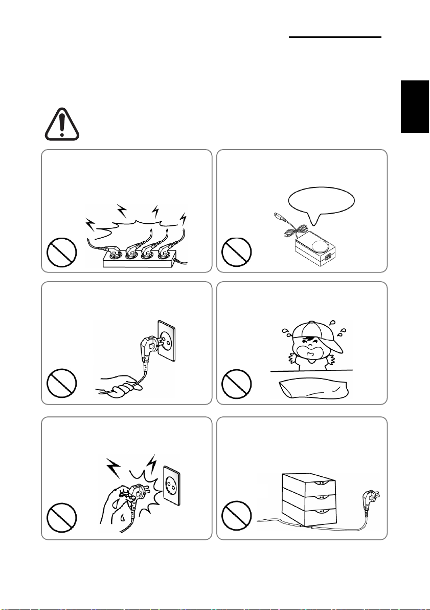
■ Safety Precautions
In using the present appliance, please keep the following safety regulations in order to
prevent any hazard or material damage.
WARNING
Violating following instructions can cause serious injury or death.
Do not plug several products in one multi-outlet.
• This can provoke over-heating and a fire.
• If the plug is wet or dirty, dry or wipe it before usage.
• If the plug does not fit perfectly with the outlet, do not plug in.
• Be sure to use only standardized multi-outlets.
You must use only the supplied adapter.
• It is dangerous to use other adapters.
ONLY SUPPLIED ADAPTER
English
PROHIBITED
Do not pull the cable to unplug.
• This can damage the cable, which is the origin of a fire or a
breakdown of the printer.
PROHIBITED
Do not plug in or unplug with your hands wet.
• You can be electrocuted.
PROHIBITED
PROHIBITED
Keep the plastic bag out of children’s reach.
• If not, a child may put the bag on his head.
PROHIBITED
Do not bend the cable by force or leave it under any
heavy object.
• A damaged cable can cause a fire.
PROHIBITED
Rev. 1.00
-2-
Page 4

WARNING
Violating following instructions can cause slight wound or damage the appliance.
If you observe a strange smoke, odor or noise from
the Display, unplug it before taking following
measures.
• Switch off the Display and unplug the set from the mains.
• After the disappearance of the smoke, call your dealer to
repair it.
BCD-1000 Series
Keep the desiccant out of children’s reach.
• If not, they may eat it.
English
TO UNPLUG
Display
Install the printer on the stable surface.
• If the Display falls down, it can be broken and you can hurt
yourself.
Display
PROHIBITED
Do not let water or other foreign objects in the
Display.
• If this happened, switch off and unplug the Display before
calling your dealer.
PROHIBITED
Display
PROHIBITED
Use only approved accessories and do not try to
disassemble, repair or remodel it for yourself.
• Call your dealer when you need these services.
DISASSEMBLING
PROHIBITED
Display
Rev. 1.00
-3-
Page 5

BCD-1000 Series
■ Warning - U.S.A
This equipment has been tested and found to comply with the limits for a Class A digital
device pursuant to Part 15 of the FCC Rules. These limits are designed to provide
reasonable protection against harmful interference when the equipment is operated in a
commercial environment. This equipment generates uses, and can radiate radio frequency
energy and if not installed and used according to the instruction manual, may cause
harmful interference to radio communications. Operation of this equipment in a residential
area is likely to cause harmful interference in which case the user will be required to
correct the interference at his/her own expense.
1. The VFD on the Display Unit is sensitive to shock.
Any jarring, throwing, or dropping of the product package can easily result in product
damage and malfunction. Please exercise care in handling.
2. Make sure to use the main cable and power unit included in the product package. Any
use of other such products can result in damage and shortening of product life.
3. The VFD Module is highly susceptible to damage from static electricity. For any product
servicing that requires product disassembly, make sure to place aluminum or copper foil
and/or conductive foam on the conductor surface during work.
4. Use of any freon-based chemical products is strictly prohibited. Any use of a freonbased spray can cause a static electrical charge that can damage the product.
5. Users are encouraged to carefully review all precautions and warning indications for
product installation and use.
■ Waste Electrical and Electric Equipment (WEEE)
their local government office, for details of where and how they can take this item for
environmentally safe recycling. Business users should contact their supplier and check the
terms and conditions of the purchase contract. This product should not be mixed with other
commercial wastes for disposal.
This marking shown on the product or its literature, indicates that is should not
be disposed with other household wastes at the end of its working life, To
prevent possible harm to the environment or human health from uncontrolled
waste disposal, please separate this from other types of wastes and recycle it
responsibly to promote the sustainable reuse of material resources. Household
users should contact either the retailer where they purchased this product, or
English
Rev. 1.00
-4-
Page 6

BCD-1000 Series
■ Table of Contents
1. Complete Product Configuration .................................................................................. 6
1-1 Diagrams by Product Type ..........................................................................................6
1-2 Pre-Installation Precautions.........................................................................................6
2. Unpacking........................................................................................................................ 7
2-1 BCD-1000D Type ........................................................................................................7
2-2 BCD-1000DN Type...................................................................................................... 7
2-3 BCD-1000W Type........................................................................................................ 8
2-4 BCD-1000WN Type ..................................................................................................... 8
3. Defaults & Options by Product Type ............................................................................ 9
3-1 Serial Type................................................................................................................... 9
3-1-1 Direct Type : Direct connection with the VFD, bypassing the Board .............. 9
3-1-2 Pass through Type (Data : Host (PC) → VFD → Printer)............................... 9
3-2 USB Type (Host (PC) → VFD, Host → Printer) ........................................................ 10
4. Connection Type & Size ............................................................................................... 11
4-1 BCD-1000D Type ......................................................................................................11
4-2 Size............................................................................................................................12
4-2-1 Desk Top Type............................................................................................... 12
4-2-2 Wall Mount Type ............................................................................................12
4-2-3 Etc. ................................................................................................................12
5. Function ......................................................................................................................... 13
5-1 Rotation .....................................................................................................................13
5-2 Angling.......................................................................................................................14
6. Connection .................................................................................................................... 15
6-1 Direct Type Pin Connection....................................................................................... 15
6-1-1 Interface Specification ...................................................................................15
6-1-2 Connector Signal Assignments ..................................................................... 16
6-1-3 Installation Instructions.................................................................................. 17
6-1-4 Signal Assignments (Cable-end DSUB)........................................................17
6-1-5 DC Power Jack.............................................................................................. 17
6-2 Serial pin Connection ................................................................................................ 18
6-2-1 Host interface connector ............................................................................... 18
6-2-2 Host interface connector signal assignments ............................................... 18
6-2-3 Printer interface connector ............................................................................ 19
6-2-4 Printer interface connector signal assignments ............................................ 19
7. Switches.........................................................................................................................20
7-1 Display Switch ...........................................................................................................20
7-2 DIP switches .............................................................................................................. 20
7-3 Memory Switches ...................................................................................................... 21
8. Power Control ...............................................................................................................22
8-1 Serial Board ............................................................................................................... 22
8-1-1 Jumper1......................................................................................................... 22
8-1-2 Jumper2......................................................................................................... 22
8-2 USB Board................................................................................................................. 23
9. USB Installation ............................................................................................................24
9-1 Virtual COM driver installation (Only BCD-1000DU/WU)..........................................24
English
Rev. 1.00
-5-
Page 7
BCD-1000 Series
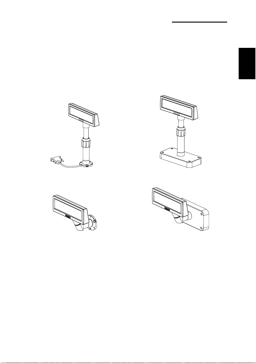
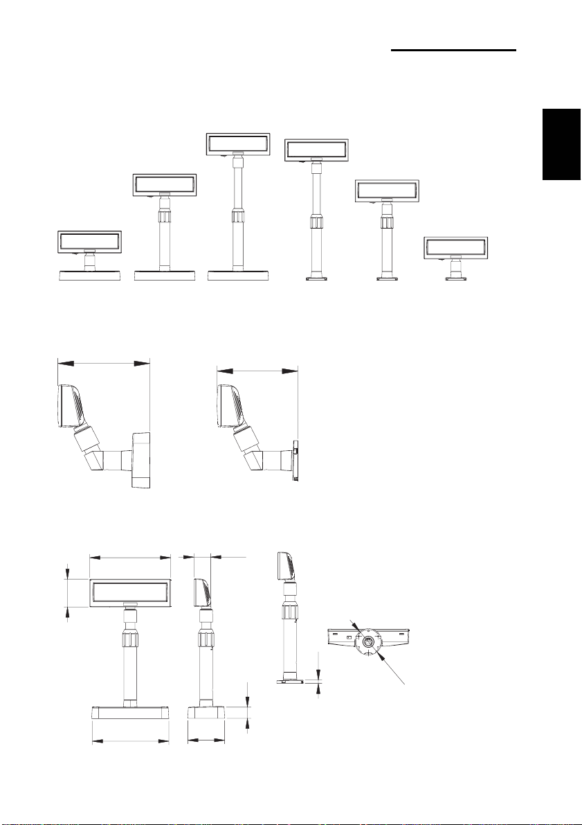
1. Complete Product Configuration
1-1 Diagrams by Product Type
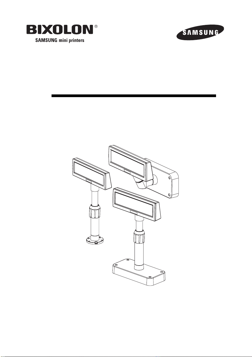
The display types offered include the following :
Desk-Top Type (BCD-1000D), Desk-Top Fix Type (BCD-1000DN),
and Wall Mount Types (BCD-1000W, BCD-1000WN).
The DF & WF types do not have a PCB.
English
BCD-1000DN
BCD-1000WN
1-2 Pre-Installation Precautions
1-2-1 Avoid locations in direct sunlight or subject to excessive heat.
1-2-2 Avoid using or storing the printer in places subject to excessive moisture.
1-2-3 Do not use or store the printer in a dusty or dirty area. Avoid places subject to
intense vibration or shock.
1-2-4 Choose a stable and flat place for proper use of the printer.
1-2-5 Make sure that there is enough space around the printer so that it can be used easily.
BCD-1000D
BCD-1000W
Rev. 1.00
-6-
Page 8
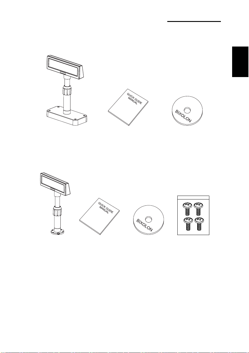
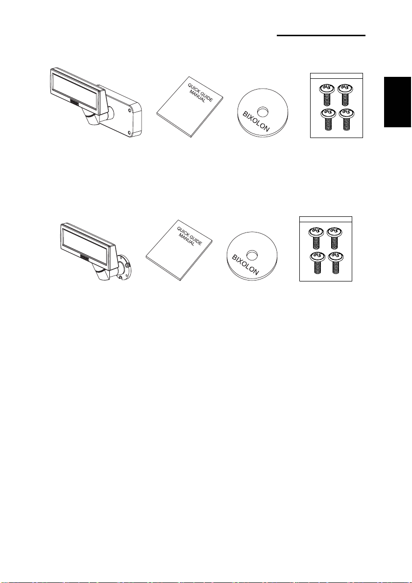
2. Unpacking
2-1 BCD-1000D Type
Display Set Manual Install CD
2-2 BCD-1000DN Type
BCD-1000 Series
English
Display Set Manual Install CD Screw
(M3*10) Tapping
Rev. 1.00
-7-
Page 9
BCD-1000 Series
2-3 BCD-1000W Type
Display Set Manual Install CD Screw
(M3*10) Tapping
2-4 BCD-1000WN Type
Display Set Manual Install CD Screw
(M3*10) Tapping
※ NOTE
Check to see if all components listed above are present and are undamaged after opening
the box. If any component is damaged or missing, contact the dealer from which the
product was purchased.
English
Rev. 1.00
-8-
Page 10
BCD-1000 Series
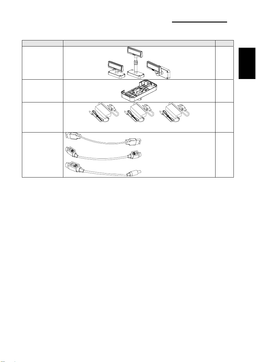
3. Defaults & Options by Product Type
3-1 Serial Type
3-1-1 Direct Type : Direct connection with the VFD, bypassing the Board
Item VFD- Serial Etc
Set Default
English
Connection of Serial Jack via separate SMPS
Usage Voltage: 5~24V(2pin)
Connection
Power Default
5V (K410-00001A)
3-1-2 Pass through Type (Data : Host (PC) → VFD → Printer)
Item VFD- Serial Etc
Set Default
Board Default
Power Option
24V,2.5A: 24V, 1.5A : 5V
K404-00007A K402-00008B K410-00001A
9PM.25PF (K604-00086A)
Cable Option
Rev. 1.00
Power Cable 3P/3P 1.8M (K610-00005B)
Power Cable 3P/2P 1.8M (K610-00005G)
-9-
Page 11
BCD-1000 Series
3-2 USB Type (Host (PC) → VFD, Host → Printer)
Item VFD- USB Etc
Set Default
English
Board Default
Power Option
Cable Option
24V,2.5A: 24V, 1.5A : 5V
K404-00007A K402-00008B K410-00001A
USB Cable,1.8M (K604-00033A)
Power Cable 3P/3P 1.8M (K610-00005B)
Power Cable 3P/2P 1.8M (K610-00005G)
Rev. 1.00
-10-
Page 12
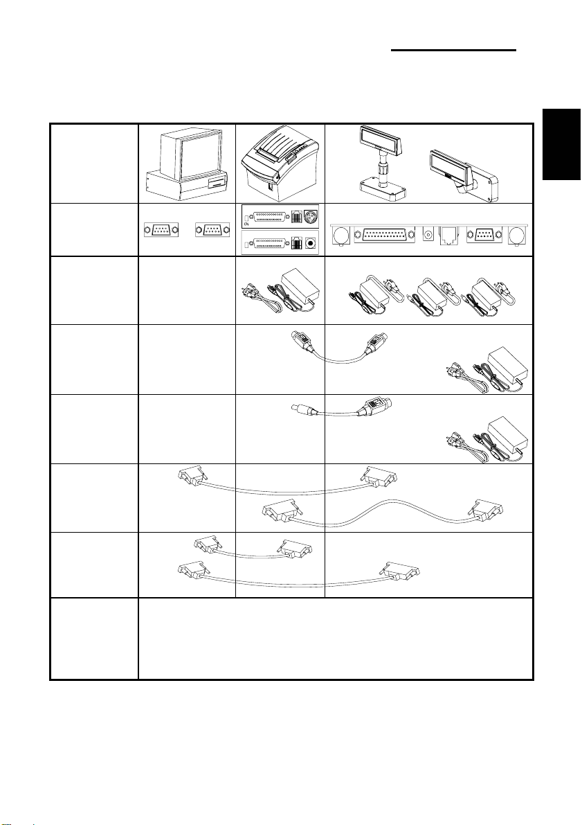
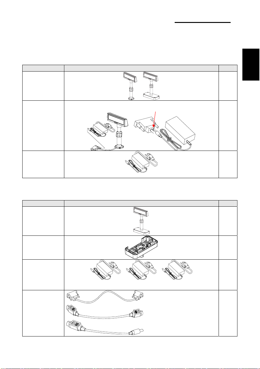
4. Connection Type & Size
4-1 BCD-1000D Type
Basic Units
BCD-1000 Series
English
Interface
A B C D E F
Power
Connection
Method 1
VFD Separate
Power Supply
Power
Connection
Method 2
3 pin 3 pin
5~24V
SMPS→VFD
→Pinter
Power
Connection
Method 3
2 pin 3 pin
SMPS→VFD
→Pinter
Cable
Connection
9 pin
25 pin
Method 1
Host→VFD
→Printer
Cable
Connection
Method 2
9 pin
9 pin
25 pin
25 pin
25 pin
A: Power Supply Connector (Out DC 24V, 3pin)
B: Host Interface Connector (D-SUB 25pin, Female)
Etc
C: Power Supply Connector (In DC 5~24V, 2pin)
D: Display Unit Connector
E: Printer Interface Connector (D-SUB 9pin, Male)
F: Power Supply Connector (In DC 24V, 3pin)
* The Power Connection Method for the Serial Type including the
SMPS → VFD → Printer Connection Method and separate power supply for the
VFD is feasible for the USB TYPE as well.
24V
24V
9 pin
Rev. 1.00
-11-
Page 13
4-2 Size
4-2-1 Desk Top Type
533mm
BCD-1000 Series
English
511mm
385mm
179mm
4-2-2 Wall Mount Type
158mm
4-2-3 Etc.
231mm
364mm
158mm
151.9mm
47.9mm
80mm
Rev. 1.00
218mm
105mm
φ75.8mm
9.6mm
32mm
-12-
Page 14
BCD-1000 Series
5. Function
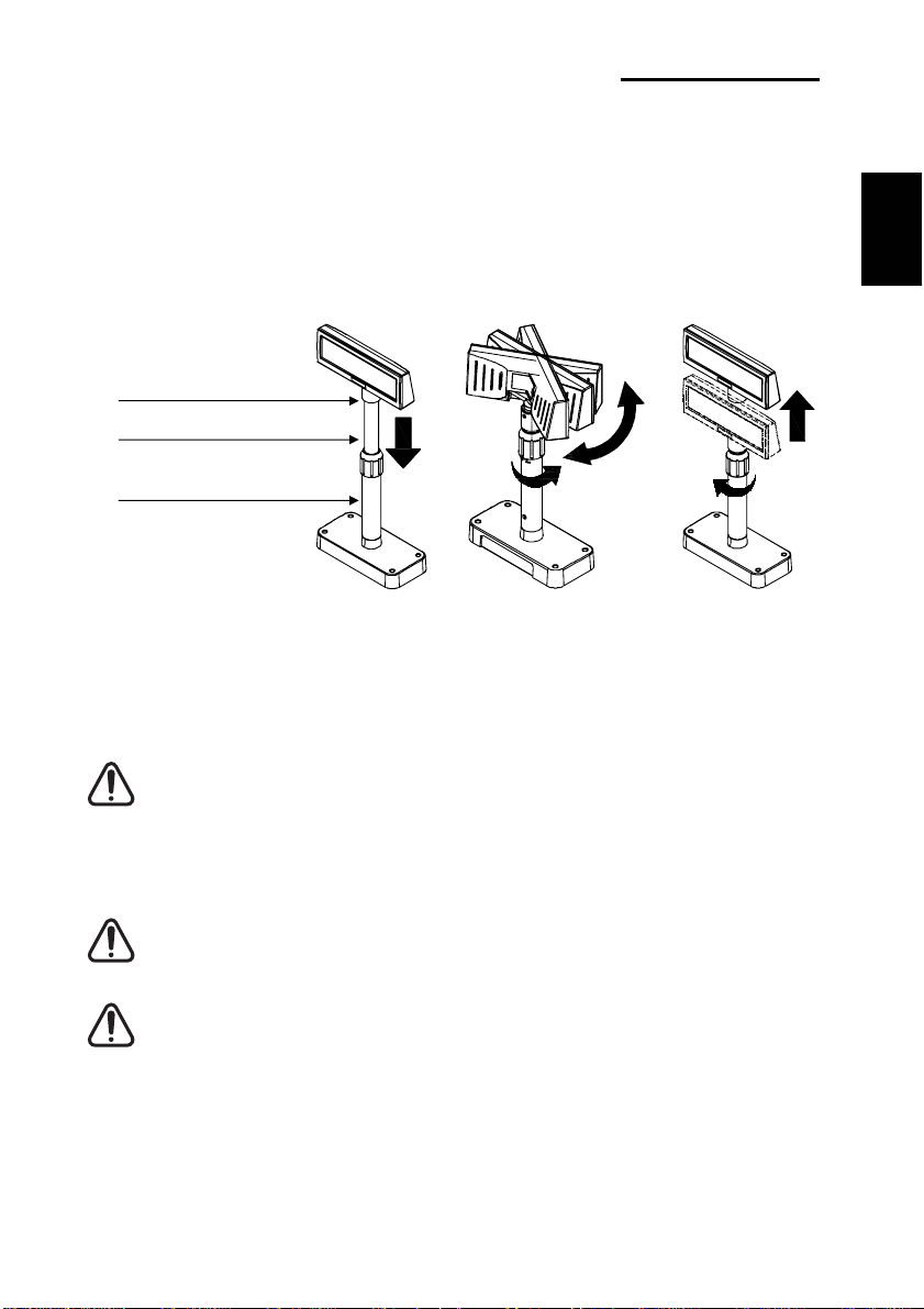
5-1 Rotation
This product allows display rotation to any position or angle desired by the user.
Please adhere to the following instructions during installation to prevent possible product
damage and/or malfunction.
Following assembly, follow the sequence below to fix the DISPLAY in the desired position.
POLE-ADJUST
NUT-FIX
POLE-MAIN
English
(a) (b) (c)
(a) Lower the DISPLAY UNIT in the direction of the arrow.
Rotate the NUT-FIX to allow for lowering.
(Please refer to the product OPEN/CLOSE label.)
(b) Rotate the DISPLAY UNIT to the desired angle.
Do not rotate the DISPLAY UNIT in any direction for more that one full revolution.
(Beware as the DISPLAY UNIT can be rotated continuously.)
(C) After setting the DISPLAY to the desired position, secure the NUT-FIX. (When raising
the DISPLAY UNIT, lateral movement is prevented.) Make sure to tighten the NUT-FIX
after raising the DISPLAY UNIT to the desired height.
As excessive tightening of the NUT-FIX can result in product damage and/or
malfunction, secure only to the extent that the DISPLAY UNIT is fixed and does not
move.
As shown in figure (A), make sure to fully lower the DISPLAY UNIT before rotating.
Rotation of the DISPLAY UNIT when it is not fully lowered will produce a clicking
sound. This sound does not indicate any product breakage and is a result of the
friction between the POLE-MAIN RIB and the rotation section within the POLE-ADJUST.
If the DISPLAY UNIT is fully lowered, this sound will not be produced.
Rev. 1.00
-13-
Page 15
BCD-1000 Series
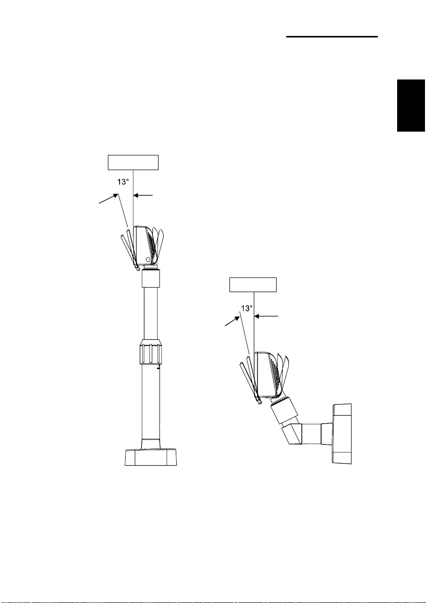
5-2 Angling
This product allows display tilting to any angle desired by the user. Please adhere to the
following instructions during installation to prevent possible product damage and/or
malfunction.
TILT ANGLE : The display can be angled left and right from the Center Line in 13° angle
intervals for a total of 4 steps, 5 positions. (Angling: 52°max.)
Center Line
Center Line
English
Rev. 1.00
-14-
Page 16
6. Connection
6-1 Direct Type Pin Connection
BCD-1000 Series
English
6-1-1 Interface Specification
Signal specifications
Data transmission Serial
Synchronization Synchronous
Handshaking (*) DTR/DSR control
Signal levels MARK = -3 to -15 V
logic = “1” OFF
SPACE = +3 to +15 V logic = “0” ON
Baud Rate (*) 1200, 2400, 4800, 9600, 19200, 38400, 57600, 115200 bps
(bps : bits per second)
Data word length (*) 7 bits, 8 bits
Parity (*) None, odd, even
Stop bits 1 or more
(*) Selected by the DIP switches.
Rev. 1.00
-15-
Page 17
BCD-1000 Series
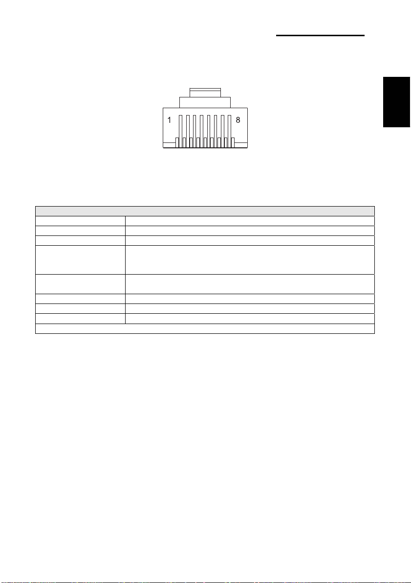
6-1-2 Connector Signal Assignments
Pin
Signal
NO
Name
1 FG - Frame ground
2 TXD Output
3 RXD Input Receive data from the printer
4 DSR Input
5 DTR Output
6 SG - Signal GND
7 PS - Power supply terminal
8 PG - Flyback line for power supply
NOTES※
(*1) For the data pass through and the stand alone, refer to SVC Manual
connection methods for detail.
(*2) [DTR MARK] can be set by the US v command. This case differs from the
above-mentioned.
[DTR MARK] Refer to the US v command in section 4, Command Description.
Signal
Direction
Function
1) When the BDC-1000 is connected with the data pass
through(*1) : Transmit data to the printer
2) When the BDC-1000 is connected in a stand-alone :
Transmit data to the host
This indicates whether the printer is ready to receive data.
1) When the BCD-1000 is connected with a data pass
through(*1) :
[MARK] : The printer is not ready to receive data
[SPACE] : The printer is ready to receive data
2) When the BDC-1000 is connected in a stand-alone :
[MARK] : The host is not ready to receive data
[SPACE] : The host is ready to receive data
This indicates whether the display is ready to receive data
(*2).
[SPACE] The display can receive data.
[MARK] The display cannot receive data.
[DTR MARK]
DTR goes to MARK under the following conditions :
① The period from when the power is turned on to when
the display first becomes ready to receive data.
② When the self-test is executed.
③ When the remaining space in the receive buffer
becomes 40bytes or less (buffer-full state).
④ When [DSR MARK] is on, if the printer is selected by a
peripheral device command. (When the BCD-1000 is
connected with the data pass through.)(*1)
[DTR SPACE]
DTR goes to SPACE under the following conditions :
① When the display first becomes ready to receive data
after power-on.
② When the self-test has ended.
③ When the remaining space in the receive buffer
becomes 50bytes or more after it became 40bytes or
less once.
English
Rev. 1.00
-16-
Page 18

BCD-1000 Series
6-1-3 Installation Instructions
STEP1. Turn the computer system power off.
STEP2. Connect the Display Cable to the RS-232 Port of the Computer.
STEP3. Connect the DC Power source by the appropriate DC Power adapter.
STEP4. Turn on the computer and the power supply unit, the display will be on and ready
for receiving data.
English
6-1-4 Signal Assignments (Cable-end DSUB)
1 2 3 4 5 6 7 8 9
pin Name NC RXD TXD DTR GND DSR RTS CTS NC
Short
Connection
6-1-5 DC Power Jack
NOTE※
To use 5V DC Power source should modify the PCB Circuit in factory.
MAX 300 ~ 1350mA. +5VDC ~ +24VDC.
Rev. 1.00
-17-
Page 19

BCD-1000 Series
6-2 Serial pin Connection
6-2-1 Host interface connector
The option stand provides the host interface connector (D-SUB 25 pin Female type).
English
6-2-2 Host interface connector signal assignments
Pin
Signal
NO
Name
1 FG - Frame ground
2 TXD Output
3 RXD Input Receive data from the host (host → DM)
4(*1) RTS Output Same as DTR
6(*2) DSR Input
7 GND - Signal ground
20(*1) DTR Output
NOTES※
(*1) Make sure to use either one of the RTS or the DTR terminal. Otherwise,
the built-in RS-232 driver IC may be broken.
Signal
Direction
1) When the BDC-1000 is connected when a passthrough
connection :Transmit data to the host from the printer
2) When the BDC-1000 is connected as a stand-alone :
Transmit data to the host from the DM
Indicates whether the host is ready to receive data.
[SPACE] The host is ready to receive data.
[MARK] The host is not ready to receive data.
This indicates whether the display is ready to receive data.
[SPACE] The display can receive data.
[MARK] The display cannot receive data.
[DTR MARK]
DTR goes to MARK under the following conditions :
① The period from when the power is turned on to
when the display first becomes ready to receive data.
② When the self-test is executed.
③ When the remaining space in the receive buffer
becomes 40bytes or less (buffer-full state).
④ When [DSR MARK] is on, if the printer is selected
by a peripheral device command.
[DTR SPACE]
DTR goes to SPACE under the following conditions :
① When the display first becomes ready to receive
data after power-on.
② When the self-test has ended.
③ when the remaining space in the receive buffer
becomes 50bytes or more after it became
40bytes or less once.
Function
Rev. 1.00
-18-
Page 20

BCD-1000 Series
6-2-3 Printer interface connector
The option stand provides the printer interface connector (D-SUB 9 pin Male type).
English
6-2-4 Printer interface connector signal assignments
Pin
NO
Signal
Name
2 RXD Input Receive data from the printer (printer → host)
3 TXD Output Transmit data to the printer (DM → Printer)
4 DTR Output Indicates whether the host is ready to receive data.
5 GND - Signal
6 DSR Input This indicates whether the display is ready to receive
9 RESET Output Reset signal to the printer (host → printer)
Signal
Direction
[SPACE] The host is ready to receive data.
[MARK] The host is not ready to receive data.
data from the printer.
[SPACE] The printer can receive data. When the printer
[MARK] The printer cannot receive data.
becomes ready to receive data the SPACE is
output.
Even if the printer becomes readyto receive
data, the MARK is not output.
Function
Rev. 1.00
-19-
Page 21

BCD-1000 Series
7. Switches
7-1 Display Switch
7-1-1 Feature : A Display Switch is located on the bottom of the display panel.
7-1-2 Function : Turns the power supply on/off.
7-2 DIP switches
7-2-1 Feature : Two DIP switches are located on the back of the display panel.
7-2-2 Functions : The DIP switch settings are read only when the power is turned on.
7-2-3 DIP S/W #1 Function (RS-232 Serial Input Setting)
No. Function Switch OFF Switch ON
1 Default Setting DIP Switch Values EEP-ROM Data Leading
2 N.C (No Connection) Reserved for Future Using Reserved for Future Using
3 Display Viewing Side Customer Side Operator Side
4 Self-test Execution Does not execute Executes
5~8 Command Emulation
7-2-4 DIP S/W #2 Function (Command Emulation Mode and Self Test Setting)
No. Function Switch OFF Switch ON
1 Data Length 8 bits 7 bits
2 Parity using Non parity Parity
3 Parity Selection Odd Even
4~6
7~8 N.C (No Connection) Reserved for Future Using Reserved for Future Using
Therefore, changing the settings while the power is on has no effect.
5 6 7 8
5 6 7 8
Command
Emulation
0 0 0 0 Samsung VFD 1 0 0 0 NCR Real POS
0 0 0 1 Epson ESC/POS 1 0 0 1 PD6000
0 0 1 0 ADM787/788 1 0 1 0 ICD2002
0011 DSP800 10 1 1 Reserved
0 1 0 0 AEDEX 1 1 0 0 Reserved
0 1 0 1 UTC Standard 1 1 0 1 Reserved
0 1 1 0 UTC Enhance 1 1 1 0 Reserved
0111 CD5220 1 1 1 1 Reserved
(“0” : S/W OFF, “1” : S/W ON)
4 5 6 Baud-rate 4 5 6 Baud-rate
0 0 0 9,600 bps 1 0 0 115,200 bps
Baud-rate
Selection
0 0 0 4,800 bps 1 0 1 57,600 bps
0 1 1 2,400 bps 1 1 0 38,400 bps
0 1 0 1,200 bps 1 1 1 19,200 bps
(“0” : S/W OFF, “1” : S/W ON)
Command
Emulation
English
Rev. 1.00
-20-
Page 22

BCD-1000 Series
7-3 Memory Switches
The following settings other than the DIP switch can be changed by software. These
settings become effective after the power is turned on or initialization is executed by a
command.
No. Function Default Content to be set Range to be set
Msw 10
Msw 11
Msw 12 Brightness adjustment n=4 100% 1-4
Msw 13
Msw 14 Cursor display Selected Selected 0, 1, 48, 49
Character code table
section
International character set
selection
Selection of the
peripheral devices
n=0 Page 0 is selected
n=0 U.S.A is selected 0-13
n=2 Display is selected 1-3
0-5, 16-19,
254, 255
English
Rev. 1.00
-21-
Page 23

8. Power Control
8-1 Serial Board
8-1-1 Jumper1
Connection type JP1 Jack Type
Input Power (5~24VDC) 1-2
Jumper1
BCD-1000 Series
English
Jumper1 - Power
Jumper2-Cable
Jumper2
Location J1
Input Power (24VDC) 2-3
N/C 4-5
Out power to print(24VDC)
(Pass through Type)
8-1-2 Jumper2
Some functions depend on the device’s connection to the BCD-1000, such as whether a
printer is connected or not with a data pass through connection, or stand alone connection.
Connection type JP2 JP2 Function
Data pass though
(default setting)
Only SERIAL 2-3 5-6 No printer is connected.
1-2 4-5
5-6
Can connect a printer which does not support the
Location CN1
Location CN2
ESC = command.
Rev. 1.00
-22-
Page 24

8-2 USB Board
BCD-1000 Series
Jumper1
English
Jumper1
Connection type JP1 Jack Type
Input Power (5~24VDC) 1-2
Input Power (24VDC) 2-3
N/C 4-5
Out power to print (24VDC)
(Pass through Type)
Location J1A
Location CN3A
5-6
Location CN4A
Rev. 1.00
-23-
Page 25

BCD-1000 Series
9. USB Installation
9-1 Virtual COM driver installation (Only BCD-1000DU/WU)
PC requires software installation when it detects new hardware connected to USB Port.
First, connect BDC-1000DU/WU (USB) to PC USB Port and install software
and set the conditions as below.
9-1-1 Connect BDC-1000DU/WU (USB) to PC USB Port. Message will pop up Found New
Hardware.
9-1-2 Select Install from a list or specific location (Advanced).
English
9-1-3 Select the location VirtualCOM_V9052154 by Browse and select Next.
Rev. 1.00
-24-
Page 26

BCD-1000 Series
9-1-4 Message pops up again at right bottom of PC Found New Hardware (USB Serial
Port) when it completes.
9-1-5 Repeat step 1 thru 3 again at Found New Hardware Wizard. It installs twice.
9-1-6 Open Device Manager (Start > Control Panel > System > Hardware > Device
Manager)
English
9-1-7 Select USB Serial Port(COM x) and click on the right button of mouse. Then select
Properties. COM port is automatically numbered and it varies from PC port
occupation conditions.
Rev. 1.00
-25-
Page 27

BCD-1000 Series
9-1-8 Set Serial communication conditions and select Advanced.
9-1-8-1 Preset Serial conditions are 19200 bps, 8 data bit, none parity, hardware flow
control.
9-1-8-2 They must be the same with Master setting and application program Serial
setting.
English
9-1-9 Check in the boxes of Serial Enumerator and Serial printer. Then select OK. Now
Virtual COM driver has been installed Successfully.
(Windows 98 does not have the boxes of Serial enumerator and Serial printer)
Rev. 1.00
-26-
Page 28

Benutzerhandbuch (Deutsch)
BCD-1000 Serie
Kundendisplay
Rev. 1.00
http://www.samsungminiprinters.com
Page 29

BCD-1000 Serie
V
■ Sicherheitsmaßnahmen
Beachten Sie bitte folgende Sicherheitsregeln bei der Benutzung dieses Geräts, um
Gefahren und Materialschäden zu vermeiden.
WARNUNG
Die Missachtung folgender Anweisungen kann zu ernsthaften Verletzungen
Schließen Sie nicht mehrere Geräte an eine
Mehrfachsteckdose.
• Dies kann zu Überhitzung und Feuer führen.
• Falls der Stecker naß oder schmutzig ist, trocknen Sie ihn ab
bevor Sie ihn benutzen.
• Falls der Stecker nicht korrekt in die Steckdose passt,
stecken Sie ihn nicht ein.
• Benutzen Sie ausschließlich Standard Mehrfachsteckdosen.
VERBOTEN
oder zum Tod führen.
Sie dürfen ausschließlich den mitgelieferten
Adapter benutzen.
• Die Benutzung anderer Adapter ist gefährlich.
NUR MITGELIEFERTER
ADAPTER
Deutsch
Ziehen Sie nicht am Kabel, um auszustecken.
• Dies kann das Kabel beschädigen und somit zu Feuer oder
Ausfall des Druckers führen.
ERBOTEN
Stecken Sie weder ein noch aus mit nassen
Händen.
• Sie könnten einen Stromschlag erleiden.
VERBOTEN
Halten Sie die Plastiktüte fern von Kindern.
• Falls nicht, könnte ein Kind sie auf seinen Kopf setzen.
VERBOTEN
Biegen Sie das Kabel nicht mit Gewalt oder legen es
unter schwere Gegenstände.
• Ein beschädigtes Kabel kann ein Feuer verursachen.
VERBOTEN
Rev. 1.00
-2-
Page 30

WARNUNG
Die Missachtung folgender Anweisungen kann leichte Verletzungen oder
Falls Sie Rauch, Geruch oder Geräusche aus Ihrem
Display bemerken, stecken Sie ihn sofort aus,
bevor Sie folgende Maßnahmen ergreifen.
• Schalten Sie das Display aus und trennen Sie das Gerät von
der Stromversorgung.
• Nachdem der Rauch abgezogen ist, rufen Sie Ihren Händler
zur Reparatur an.
Geräteschäden verursachen.
BCD-1000 Serie
Halten Sie das Trocknungsmittel fern von Kindern.
• Falls nicht könnten sie es essen.
Deutsch
ZUM AUSSTECKEN
Display
Installieren Sie das Display auf einer stabilen
Fläche.
• Falls das Display herunter fällt, kann es kaputt gehen und
Sie könnten sich verletzen.
Display
VERBOTEN
Lassen Sie weder Wasser noch Fremdkörper in den
Display eindringen.
• Falls dies doch passieren sollte, schalten Sie den Display
aus und stecken ihn aus, bevor Sie Ihren Händler anrufen.
VERBOTEN
Display
VERBOTEN
Benutzen Sie ausschließlich zugelassenes Zubehör
und versuchen Sie nicht das Gerät selbst zu öffnen,
reparieren oder umzubauen.
• Rufen Sie Ihren Händler an, sollten Sie solche Dienste
benötigen.
UMBAU
VERBOTEN
Display
Rev. 1.00
-3-
Page 31

BCD-1000 Serie
■ Warnung - U.S.A
Dieses Gerät ist geprüft worden und entspricht den Vorschriften eines Klasse A
Digitalgeräts gemäß Teil 15 der FCC Regeln. Diese Regeln sollen einen adäquaten Schutz
vor schädlichen Störungen bieten, falls das Gerät in einem kommerziellen Umfeld benutzt
wird. Dieses Gerät benutzt, und kann Radiofrequenzenergie ausstrahlen und fall es nicht
entsprechend dem Benutzerhandbuch betrieben wird, kann es schädliche Störungen von
Radiokommunikationen verursachen. Der Betrieb dieses Geräts in einer Wohngegend wird
vermutlich schädliche Störungen verursachen, die der Benutzer auf eigene Kosten
korrigieren muss.
1. Das VFD des Displays ist schockempfindlich.
Jedes Erschüttern, Werfen oder Fallenlassen des Produktpakets kann leicht zu
Produktschäden und Fehlfunktion führen. Behandeln Sie es bitte mit Vorsicht.
2. Benutzen Sie ausschließlich die in der Produktpackung befindlichen Stromkabel
und -versorgung. Die Benutzung anderer Produkte kann zu Schäden und zu einer
verkürzten Lebensdauer des Produkts führen.
3. Das VFD-Modul kann sehr leicht durch statische Elektrizität beschädigt werden.
Bei allen Arbeiten am Produkt, die einen Ausbau erfordert, legen Sie unbedingt eine
Alu- oder Kupferfolie und/oder leitenden Schaumstoff auf die leitende Fläche während
der Arbeit.
4. Die Benutzung von chemischen Produkten auf Freon Basis ist streng verboten.
Die Benutzung eines Sprays auf Freon Basis kann eine statische elektrische Ladung
erzeugen, die das Produkt beschädigen kann.
5. Benutzer sollten alle Vorsichtshinweise und Warnungen zur Produktinstallation und
Benutzung sorgfältig prüfen.
■ WEEE Kennzeichnung
Materialresourcen zu fördern. Privatbenutzer sollten entweder den Händler bei dem sie
das Gerät gekauft haben oder ihre Gemeinde fragen, wo sie das Gerät zur
umweltgerechten Wiederverwertung abgeben können. Kommerzielle Benutzer sollten
ihren Lieferanten fragen und die Bedingungen ihres Kaufvertrags prüfen. Dieses Gerät
sollte nicht zusammen mit sonstigem kommerziellen Abfall entsorgt werden.
Dieses Kennzeichen auf dem Gerät oder in seiner Dokumentation weist
daraufhin, dass es nicht zusammen mit sonstigem Hausmüll nach Beendigung
seiner Lenbensdauer entsorgt werden darf. Um mögliche Umwelt- und
Gesundheitsschäden durch unkontrollierte Abfallbeseitigung zu vermeiden,
trennen Sie es bitte von sonstigem Abfall und führen Sie es einer vernünftigen
Wiederverwertung zu, um eine dauerhafte Wiederverwendung unserer
Deutsch
Rev. 1.00
-4-
Page 32

BCD-1000 Serie
■ Inhalt
1. Vollständige Produktkonfiguration...............................................................................6
1-1 Schaubilder Nach Produkttyp ......................................................................................6
1-2 Vorsichtsmaßnahmen vor Installation ......................................................................... 6
2. Entpacken........................................................................................................................ 7
2-1 Typ BCD-1000D ..........................................................................................................7
2-2 Typ BCD-1000DN........................................................................................................ 7
2-3 Typ BCD-1000W.......................................................................................................... 8
2-4 Typ BCD-1000WN ....................................................................................................... 8
3.
Standardmässige und Optionale Komponenten Nach Produkt typ
3-1 Typ Seriell.................................................................................................................... 9
3-1-1 Direkter Typ: Direkter Anschluss mit VFD unter Umgehung des Boards ....... 9
3-1-2 Durchführungs Typ (Daten: Host (PC) → VFD → Drucker)............................9
3-2 Typ USB (Host (PC) → VFD, Host → Drucker) ........................................................ 10
4. Anschluss Typ Und Grösse......................................................................................... 11
4-1 Typ BCD-1000D ........................................................................................................11
4-2 Grösse ....................................................................................................................... 12
4-2-1 Typ Desk Top................................................................................................. 12
4-2-2 Typ Wand Montage ....................................................................................... 12
4-2-3 Etc. ................................................................................................................12
5. Funktion ......................................................................................................................... 13
5-1 Drehung ..................................................................................................................... 13
5-2 Abwinklung ................................................................................................................14
6. Anschluss......................................................................................................................15
6-1 Anschluss Direkter Typ.............................................................................................. 15
6-1-1 Schnittstellendaten ........................................................................................15
6-1-2 Stecker-Signalzuordnung ..............................................................................16
6-1-3 Installations Anweisungen............................................................................. 17
6-1-4 Signalzuordnungen (Kabelende-DSUB) ....................................................... 17
6-1-5 Gleichspanungsstecker .................................................................................17
6-2 Serieller Anschluss .................................................................................................... 18
6-2-1 Host-Schnittstellenstecker............................................................................. 18
6-2-2 Signalzuordnungen Host-Schnittstellenanschluss ........................................ 18
6-2-3 Drucker-Schnittstellenanschluss ................................................................... 19
6-2-4 Signalzuordnung Drucker-Schnittstellenanschluss....................................... 19
7. Schalter .......................................................................................................................... 20
7-1 Display Schalter......................................................................................................... 20
7-2 DIP Schalter............................................................................................................... 20
7-3 Speicher-Schalter ...................................................................................................... 21
8. Leistungssteuerung...................................................................................................... 22
8-1 Serielles Board ..........................................................................................................22
8-1-1 Brücke1 .........................................................................................................22
8-1-2 Brücke2 .........................................................................................................22
8-2 USB Board................................................................................................................. 23
9. USB Installation ............................................................................................................24
9-1 Virtual COM Treiberinstallation (Nur BCD-1000DU/WU) ..........................................24
..................................9
Deutsch
Rev. 1.00
-5-
Page 33

BCD-1000 Serie
1. Vollständige Produktkonfiguration
1-1 Schaubilder Nach Produkttyp
Zu den angebotenen Displaytypen gehören: DESKTOP-TYP (BCD-1000D), FIXER
DESKTOP-TYP (BCD-1000DN) und WANDMONTAGETYPEN (BCD-1000W/WN).
Die Desktop- und Wandmontagetypen verfügen nicht über eine Leiterplatte.
Deutsch
BCD-1000DN
BCD-1000WN
1-2 Vorsichtsmaßnahmen vor Installation
1-2-1 Meiden Sie Orte in direktem Sonnenlicht oder die hohen Temperaturen ausgesetzt
sind.
1-2-2 Vermeiden Sie es den Drucker an Orten hoher Feuchtigkeit zu benutzen oder
aufzubewahren.
1-2-3 Vermeiden Sie es den Drucker an staubigen oder schmutzigen Orten zu benutzen
oder aufzubewahren. Meiden Sie Orte die starken Vibrationen oder Schocks
ausgesetzt sind.
1-2-4 Wählen Sie einen stabilen flachen Ort zur korrekten Benutzung des Druckers.
1-2-5 Sorgen Sie für genügend Platz um den Drucker herum, um ihn leicht zu benutzen.
BCD-1000D
BCD-1000W
Rev. 1.00
-6-
Page 34

2. Entpacken
2-1 Typ BCD-1000D
Displayset Handbuch Installations-CD
2-2 Typ BCD-1000DN
BCD-1000 Serie
Deutsch
Displayset Handbuch Installations-CD Schrauben
(M3*10) Gewinde
Rev. 1.00
-7-
Page 35

BCD-1000 Serie
2-3 Typ BCD-1000W
Displayset Handbuch Installations-CD Schrauben
(M3*10) Gewinde
2-4 Typ BCD-1000WN
Displayset Handbuch Installations-CD Schrauben
(M3*10) Gewinde
※ HINWEISE
Prüfen Sie nach dem Öffnen der Packung, ob alle oben aufgelisteten Komponenten
vorhanden und unbeschädigt sind. Sollte eine Komponente fehlen oder beschädigt sein,
kontaktieren Sie den Händler, bei dem Sie das Produkt erworben haben.
Deutsch
Rev. 1.00
-8-
Page 36

BCD-1000 Serie
3.
Standardmässige und Optionale Komponenten Nach Produkt typ
3-1 Typ Seriell
3-1-1 Direkter Typ: Direkter Anschluss mit VFD unter Umgehung des Boards
Posten VFD- Seriell Etc
Set Standard
Anschluss des seriellen Steckers über SMPS
Gebrauchsspannung: 5~24V (2-Polig)
Anschluss
Spannung
Standard
5V (K410-00001A)
3-1-2 Durchführungs Typ (Daten: Host (PC) → VFD → Drucker)
Posten VFD- Seriell Etc
Set Standard
Board
Standard
Spannung
Option
24V,2.5A: 24V, 1.5A : 5V
K404-00007A K402-00008B K410-00001A
9PM.25PF (K604-00086A)
Kabel
Option
SpannungsKabel 3P/3P 1.8M (K610-00005B)
Deutsch
Rev. 1.00
SpannungsKabel 3P/2P 1.8M (K610-00005G)
-9-
Page 37

BCD-1000 Serie
3-2 Typ USB (Host (PC) → VFD, Host → Drucker)
Posten VFD- USB Etc
Set Standard
Board
Standard
Spannung
Option
Kabel
Option
24V,2.5A: 24V, 1.5A : 5V
K404-00007A K402-00008B K410-00001A
USB Kabel,1.8M (K604-00033A)
SpannungsKabel 3P/3P 1.8M (K610-00005B)
SpannungsKabel 3P/2P 1.8M (K610-00005G)
Deutsch
Rev. 1.00
-10-
Page 38

4. Anschluss Typ Und Grösse
4-1 Typ BCD-1000D
Basis
Einheiten
BCD-1000 Serie
A B C D E F
Schnittstelle
Spannungs
Anschluss
Methode1
VFD
Unabh
ängige
Spannungs
5~24V
Versorgung
Spannungs
Anschluss
Methode2
3 pol
3 pol
24V
SMPS→VFD
→Drucker
Spannungs
Anschluss
Methode3
2 pol 3 pol
24V
SMPS→VFD
→ Drucker
Kabelan
Schluss
Methode1
HOST→VFD
→Drucker
Kabelan
Schluss
Methode2
Etc
9 pol
25 pol
9 pol
9 pol
A: SPANNUNGSANSCHLUSS (AUSG. DC 24V, 3-POLIG)
B: HOST-SCHNITTSTELLENANSCHLUSS (D-SUB 25PI, BUCHSE)
C: SPANNUNGSVERSORGUNGSANSCHLUSS (EING. DC 5~24V ,2-POLIG)
D: DISPLAYEINHEITENANSCHLUSS
E: DRUCKERSCHNITTSTELLENANSCHLUSS (D-SUB, 9-POLIG, STECKER)
F: SPANNUNGSANSCHLUSS (EING. DC 24V, 3-POLIG)
25 pol
25 pol
25 pol
9 pol
* Die SPANNUNGSANSCHLUSSMETHODE für den SERIELLEN TYP einschließlich der
SMPS → VFD → DRUCKERANSCHLUSSMETHODE und separater
Spannungsversorgung für das VFD ist auch für den USB-TYP möglich.
Deutsch
Rev. 1.00
-11-
Page 39

4-2 Grösse
4-2-1 Typ Desk Top
533mm
BCD-1000 Serie
511mm
385mm
179mm
4-2-2 Typ Wand Montage
158mm
4-2-3 Etc.
231mm
80mm
364mm
158mm
Deutsch
151.9mm
47.9mm
Rev. 1.00
218mm
105mm
φ75.8mm
9.6mm
32mm
-12-
Page 40

BCD-1000 Serie
5. Funktion
5-1 Drehung
Dieses Produkt erlaubt eine Rotation in jede vom Benutzer gewünschte Stellung.
Halten Sie sich bitte an folgende Anweisungen während der Installation, um mögliche
Produktschäden und/oder Fehlfunktionen zu vermeiden.
Nach der Montage führen Sie untenstehende Schritte aus, um das DISPLAY in die
gewünschte Position zu bringen.
STANGEN-JUSTIERUNG
FESTSTELL SCHRAUBE
HAUPTSTANGE
(a) (b) (c)
(a) Senken Sie das Display in Pfeilrichtung ab.
Lösen Sie die Feststellschraube zum Absenken.
(Sehen Sie auf das Produktetikett - ÖFFNEN/SCHLIESSEN.)
(b) Drehen Sie das DISPLAY in die gewünschte Position.
Führen Sie nicht mehr als eine volle Drehung des Displays in eine Richtung aus.
(Vorsicht – da das Display unendlich weitergedreht werden kann.)
(C) Nachdem Sie das Display in die gewünschte Position gedreht haben, schließen Sie die
Feststellschraube. (Bei der Erhöhung des Displays wird eine laterale Bewegung
verhindert.) Stellen Sie sicher, dass die Feststellschraube nach Erhöhung des Displays
in die gewünschte Position festgeschraubt ist.
Da ein Überdrehen der Feststellschraube zu Produktschaden und/oder
Fehlfunktion führen kann, schrauben Sie diese nur so fest, dass das DISPLAY
feststeht und sich nicht bewegen kann.
Stellen Sie sicher, dass das DISPLAY ganz abgesenkt ist bevor sie es drehen –
wie in Figur (a) abgebildet. Beim Drehen des Displays in nicht ganz abgesenkter
Position wird ein Klicken hörbar.Dieses Geräusch weist nicht auf ein
Produktschaden hin, sondern resultiert aus der Friktion zwischen Stangenhauptteil und
dem Rotationsteil der Stangenjustierung. Wenn das DISPLAY voll abgesenkt ist, wird
dieses Geräusch nicht erzeugt.
Deutsch
Rev. 1.00
-13-
Page 41

BCD-1000 Serie
5-2 Abwinklung
Dieses Produkt erlaubt die Abwinklung des Displays in jede vom Benutzer gewünschte
Stellung. Halten Sie sich bitte an folgende Anweisungen während der Installation, um
mögliche Produktschäden und/oder Fehlfunktionen zu vermeiden.
Abwinklung : Das Display kann nach links oder rechts der Mittellinie in 13°
Winkelintervallen, in insgesamt 4 Schritten, 5 Positionen, abgewinkelt
werden. (Abwinklung: max. 52°)
Center Line
Center Line
Deutsch
Rev. 1.00
-14-
Page 42

6. Anschluss
6-1 Anschluss Direkter Typ
BCD-1000 Serie
6-1-1 Schnittstellendaten
Signaldaten
Datenübertragung Seriell
Synchronisation Synchron
Quittierungsüberwachung (*) DTR/DSR-Steuerung
Signalpegel MARK = -3 bis -15 V
Logik = “1” OFF
SPACE = +3 bis +15 V Logik = “0” ON
Baudrate (*) 1200, 2400, 4800, 9600, 19200, 38400, 57600, 115200
bps
(bps : Bits pro Sekunde)
Datenwortlänge (*) 7 Bits, 8 Bits
Parität (*) Keine, ungerade, gerade
Stoppbits 1 oder mehr
(*) Auswahl über DIP-Schalter.
Deutsch
Rev. 1.00
-15-
Page 43

BCD-1000 Serie
6-1-2 Stecker-Signalzuordnung
PIN-
Signalname
Nr.
1 FG -
2 TXD Ausgang
3 RXD Eingang
4 DSR Eingang
5 DTR Ausgang
6 SG 7 PS 8 PG -
※ HINWEISE
(*1) Für Datendurchgang und Einzelgerät, siehe SVC-HANDBUCH, Anschlussmethoden.
(*2) [DTR MARK] kann durch US v-Befehl eingerichtet werden. Dieser Fall unterscheidet
sich vom oben genannten.
[DTR MARK]. Siehe US v-Befehl in Abschnitt 4, Befehlsbeschreibung.
Signal-
richtung
Funktion
Gehäusemasse
1) Bei Anschluss des BDC-1000 Datendurchgang
durch (*1): Datenübertragung zum Drucker
2) Bei Anschluss des BDC-1000 als Einzelgerät:
Datenübertragung zum Host
Datenempfang vom Drucker
Hierüber wird angezeigt, ob der Drucker bereit ist, Daten zu
empfangen.
1) Bei Anschluss des BDC-1000 Datendurchgang durch (*1):
[MARK] : Der Drucker ist nicht empfangsbereit.
[SPACE]: Der Drucker ist empfangsbereit.
2) Bei Anschluss des BDC-1000 als Einzelgerät:
[MARK] : Der Host ist nicht empfangsbereit.
[SPACE]: Der Host ist empfangsbereit.
Hierüber wird angezeigt, ob das Display bereit ist, Daten zu
empfangen (*2).
[SPACE]: Das Display ist empfangsbereit.
[MARK]: Das Display ist nicht empfangsbereit.
[DTR MARK]
DTR zu MARK unter folgenden Bedingungen:
① Zeitraum zwischen Einschalten der Spannung bis
zur erstmaligen Empfangsbereitschaft des Displays.
② Bei Selbsttestausführung.
③ Wenn der verbleibende Speicherplatz im
Empfangspuffer 40 Bytes oder weniger beträgt
(Status Puffer voll).
④ Wenn [DSR MARK] an ist, wenn der Drucker über
einen Befehl eines Peripheriegerätes ausgewählt wird.
(Wenn das BCD-1000 mit dem Datendurchgang
angeschlossen ist.)(*1)
[DTR SPACE]
DTR zu SPACE unter folgenden Bedingungen:
① Wenn das Display erstmalig nach dem Einschalten in
die Empfangsbereitschaft übergeht.
② Nach Beendigung des Selbsttests.
③ Wenn der verbleibende Speicherplatz im
Empfangspuffer 50 Bytes oder mehr beträgt, nachdem
er bei 40 Bytes oder weniger lag.
Messerde
Spannungsversorgungsanschluss
Rücklaufleitung für Spannungsversorgung
Deutsch
Rev. 1.00
-16-
Page 44

BCD-1000 Serie
6-1-3 Installations Anweisungen
SCHRITT1. Schalten Sie die Systemspannung des Computers aus.
SCHRITT2. Schließen Sie das Displaykabel an den RS-232-Port des Computers an.
SCHRITT3. Schließen Sie die Gleichspannungsquelle über den geeigneten
Wechselspannungsadapter an.
SCHRITT4. Schalten Sie Computer und Spannungsversorgungseinheit ein.
Das Display ist an und empfangsbereit.
Deutsch
6-1-4 Signalzuordnungen (Kabelende-DSUB)
1 2 3 4 5 6 7 8 9
P.Name NC RXD TXD DTR GND DSR RTS CTS NC
Kurz
Anschluss
6-1-5 Gleichspanungsstecker
※ HINWEISE
Um eine 5-Volt-Gleichspannungsquelle verwenden zu können, muss der Leiterplattenkreis
werkseitig modifiziert werden.
MAX 300 ~ 1350mA. +5VDC ~ +24VDC.
Rev. 1.00
-17-
Page 45

BCD-1000 Serie
6-2 Serieller Anschluss
6-2-1 Host-Schnittstellenstecker
Die Option Sockel bietet den Host-Schnittstellenanschluss (D-SUB, 25-polig, Buchse).
6-2-2 Signalzuordnungen Host-Schnittstellenanschluss
Pin
Signal
NO
Name
1 FG -
2 TXD Ausgang
3 RXD Eingang
4(*1) RTS Ausgang
6(*2) DSR Eingang
7 GND -
20(*1) DTR Ausgang
Signal-
richtung
Funktion
Gehäusemasse
1) Bei Anschluss des BDC-1000 bei Durchgangs anschluss: Datenübertragung vom Host zum Drucker.
2) Bei Anschluss des BDC-1000 als Einzelgerät:
Datenübertragung vom DM zum Host.
Datenempfang vom Host (Host → DM)
Wie DTR.
Zeigt an, ob der Host für den Datenempfang bereit.
[SPACE]: Der Host ist empfangsbereit.
[MARK]: Der Host ist nicht empfangsbereit.
Messerde
Hierüber wird angezeigt, ob das Display bereit ist, Daten zu
empfangen.
[SPACE]: Das Display ist empfangsbereit.
[MARK]: Das Display ist nicht empfangsbereit.
[DTR MARK]
DTR zu MARK unter folgenden Bedingungen:
① Zeitraum zwischen erstem Einschalten bis
das Display in die Empfangsbereitschaft übergeht.
② Bei Selbsttestausführung.
③ Wenn der verbleibende Speicherplatz im Empfangspuffer
40 Bytes oder weniger beträgt (Status Puffer voll).
④ Wenn [DSR MARK] an ist, wenn der Drucker über einen
Befehl eines Peripheriegerätes ausgewählt wird.
[DTR SPACE]
DTR zu SPACE unter folgenden Bedingungen:
① Wenn das Display in die Empfangsbereitschaft übergeht
nach dem Einschalten.
② Nach Beendigung des Selbsttests.
③ Wenn der verbleibende Speicherplatz im Empfangspuffer
50 Bytes oder mehr beträgt, nachdem er bei 40 Bytes
oder weniger lag.
※ HINWEISE
(*1) Stellen Sie sicher, dass Sie entweder einen der RTS oder den DTR-Anschluss
verwenden. Anderenfalls: kann die integrierte RS-232-Treiberschaltung beschädigt werden.
Deutsch
Rev. 1.00
-18-
Page 46

BCD-1000 Serie
6-2-3 Drucker-Schnittstellenanschluss
Die Option Sockel bietet den Drucker-Schnittstellenanschluss (D-SUB, 9-polig, Stecker).
6-2-4 Signalzuordnung Drucker-Schnittstellenanschluss
Pin-
Signal-
Nr.
name
2 RXD Eingang Datenempfang vom Drucker (Drucker → Host)
3 TXD Ausgang Datenübertragung zum Drucker (DM → Drucker)
4 DTR Ausgang Zeigt an, ob der Host für den Datenempfang bereit.
5 GND - Signal
6 DSR Eingang Hierüber wird angezeigt, ob das Display bereit ist,
9 RESET Ausgang Reset des Signals zum Drucker (Host → Drucker)
Signalrichtung Funktion
[SPACE]: Der Host ist empfangsbereit.
[MARK]: Der Host ist nicht empfangsbereit.
Daten vom Drucker zu empfangen.
[SPACE]: Der Drucker ist empfangsbereit.
[MARK]: Der Drucker ist nicht empfangsbereit.
Wenn der Drucker in die
Empfangsbereitschaft übergeht, ist SPACE
der Ausgang.
Auch wenn der Drucker in die
Empfangsbereitschaft
übergeht, ist MARK nicht der Ausgang.
Deutsch
Rev. 1.00
-19-
Page 47

BCD-1000 Serie
7. Schalter
7-1 Display Schalter
7-1-1 Ausstattung : Ein Display Schalter befindet sich unten am Display.
7-1-2 Funktion : Schaltet die Stromversorgung ein/aus.
7-2 DIP Schalter
7-2-1 Ausstattung : Zwei DIP Schalter befinden sich am hinteren Teil des Displays.
7-2-2 Funktionen : Die DIP Schalterstellungen werden nur gelesen wenn die Stromzufuhr
7-2-3 DIP-Schalter Nr. 1 Funktion (RS-232 serielle Eingangseinstellung)
Sch.-
Nr.
1 Standardeinstellung DIP-Schalter-Werte EEPROM-Datenführung
2 N.C (kein Anschluss)
3 Display-Anzeigeseite Kundenseite Bedienerseite
4
5~8 Befehlsemulation
7-2-4 DIP-Schalter Nr. 2 (Befehlsemulationsmodus und Selbsttesteinstellung)
Sch.-
Nr.
1 Datenlänge 8 Bits 7 Bits
2 Paritätsverwendung Keine Parität Parität
3 Paritätsauswahl Ungerade Gerade
4~6 Baudratenauswahl
7~8 N.C (kein Anschluss)
eingeschaltet ist. Daher hat eine Veränderung der Schalterstellungen
bei eingeschalteter Stromzufuhr keine Wirkung.
Funktion Schalter AUS Schalter EIN
Ausführung
Selbsttest
Reserviert für spätere
Verwendung
Wird nicht ausgeführt Wird ausgeführt
Reserviert für spätere
Verwendung
5 6 7 8 Befehls-emulation 5 6 7 8 Befehls-emulation
0 0 0 0 Samsung VFD 1 0 0 0 NCR Real POS
0 0 0 1 Epson ESC/POS 1 0 0 1 PD6000
0 0 1 0 ADM787/788 1 0 1 0 ICD2002
0 0 1 1 DSP800 1 0 1 1 Reserviert
0 1 0 0 AEDEX 1 1 0 0 Reserviert
0 1 0 1 UTC Standard 1 1 0 1 Reserviert
0 1 1 0 UTC Enhance 1 1 1 0 Reserviert
0 1 1 1 CD5220 1 1 1 1 Reserviert
(“0” : Schalter OFF, “1” : Schalter ON)
Funktion Schalter AUS Schalter EIN
4 5 6 Baudrate 4 5 6 Baudrate
0 0 0 9.600 bps 1 0 0 115.200 bps
0 0 0 4.800 bps 1 0 1 57.600 bps
0 1 1 2.400 bps 1 1 0 38.400 bps
0 1 0 1.200 bps 1 1 1 19.200 bps
(“0” : Schalter OFF, “1” : Schalter ON)
Reserviert für spätere
Verwendung
Reserviert für spätere
Verwendung
Deutsch
Rev. 1.00
-20-
Page 48

BCD-1000 Serie
7-3 Speicher-Schalter
Die folgenden Einstellungen können (ausgenommen der DIP-Schalter) über die Software
geändert werden. Diese Einstellungen treten nach Einschalten der Spannung oder durch
Initialisierungsbefehl in Kraft.
Speicher-
Schalter
Msw 10
Msw 11
Msw 12 Helligkeitseinstellung n=4 100% 1-4
Msw 13
Msw 14 Cursoranzeige Ausgewählt Ausgewählt 0, 1, 48, 49
Funktion Standard
Auswahl
Zeichencodetabelle
Auswahl internationaler
Zeichensatz
Auswahl der
Peripheriegeräte
n=0
n=0 USA ausgewählt 0-13
n=2
Zu setzender
Inhalt
Seite 0
ausgewählt
Display
ausgewählt
Zu setzender
Bereich
0-5, 16-19,
254, 255
1-3
Deutsch
Rev. 1.00
-21-
Page 49

8. Leistungssteuerung
r
r
r
ü
cke
r
8-1 Serielles Board
B
ücke1 - Spannung
B
BCD-1000 Serie
ücke2-Kabel
B
1 B
ücke2
8-1-1 Brücke1
Anschlusstyp JP1 Steckertyp
Eingangsleistung (5~24 VDC) 1-2
Ort J1
Eingangsleistung (24 VDC) 2-3
Ort CN1
N/C 4-5
Ausgangsleistung Druck
(24 VDC)
(Durchgangstyp)
5-6
Ort CN2
8-1-2 Brücke2
Einige Funktionen hängen vom Anschluss des Gerätes an das BCD-1000 ab; d. h. ob ein
Drucker angeschlossen ist oder nicht, mit Durchgangsanschluss oder als
Einzelgerätanschluss.
Anschlusstyp JP2 JP2 Funktion
Datendurchgang
(Standard-
einstellung)
1-2 4-5
Ein Drucker, der den Befehl ESC = nicht
unterstützt, kann angeschlossen werden.
Nur SERIELL 2-3 5-6 Kein Drucker angeschlossen.
Deutsch
Rev. 1.00
-22-
Page 50

8-2 USB Board
r
ü
cke
r
B
B
1
BCD-1000 Serie
ücke1
Deutsch
Anschlusstyp JP1 Steckertyp
Eingangsleistung (5~24 VDC) 1-2
Eingangsleistung (24 VDC) 2-3
N/C 4-5
Ausgangsleistung Druck
(24 VDC)
(Durchgangstyp)
Ort J1A
Ort CN3A
5-6
Ort CN4A
Rev. 1.00
-23-
Page 51

BCD-1000 Serie
9. USB Installation
9-1 Virtual COM Treiberinstallation (Nur BCD-1000DU/WU)
Ein PC benötigt eine Softwareinstallation beim Erkennen neuer Hardware am USB Port.
Zunächst, verbinden Sie den BDC-1000DU/WU (USB) mit dem PC USB Port, installieren
Sie die Software und stellen Sie die untenstehenden Bedingungen wie folgt ein.
9-1-1 Verbinden Sie den BDC-1000DU/WU (USB) mit dem PC USB Port. Die Mitteilung:
Found New Hardware erscheint.
9-1-2 Wählen Sie Install aus einer Liste oder einem bestimmten Ort (Advanced).
Deutsch
9-1-3 Wählen Sie die Location VirtualCOM_V9052154 durch Browsen und dann Next.
Rev. 1.00
-24-
Page 52

BCD-1000 Serie
9-1-4 Die Mitteilung - Found New Hardware - erscheint wieder unten rechts am PC (USB
Serial Port).
9-1-5 Wiederholen Sie die Schritte 1 bis 3 des Found New Hardware Wizards. Es wird
zweimal installiert.
9-1-6 Öffnen Sie den Device Manager (Start > Control Panel > System > Hardware >
Device Manager)
Deutsch
9-1-7 Wählen Sie USB Serial Port(COM x) und klicken Sie auf die rechte Maustaste.
Wählen Sie dann Properties. COM Port ist automatisch nummeriert und abhängig
von PC Port Belegungsbedingungen.
Rev. 1.00
-25-
Page 53

BCD-1000 Serie
9-1-8 Stellen Sie Serienkommunikationsbedingungen ein und wählen Sie Advanced.
9-1-8-1 Voreingestellte Serienbedingungen sind 19200 bps, 8 data bit, none parity,
hardware flow control.
9-1-8-2 Sie müssen bei Master setting und application program Serial setting gleich sein.
Deutsch
9-1-9 Setzen Sie Haken in die Kästchen Serial Enumerator und Serial Printer. Dann
wählen Sie OK. Jetzt ist der Virtual COM Treiber erfolgreich installiert worden.
(Windows 98 verfügt nicht über die Kästchen Serial Enumerator und Serial Printer)
Rev. 1.00
-26-
Page 54

KN10-00001A
 Loading...