

Page 1
Level
7.
Disassembly and Assembly Instructions
7-1.
Repair
2
7-1-1.
Disassembly
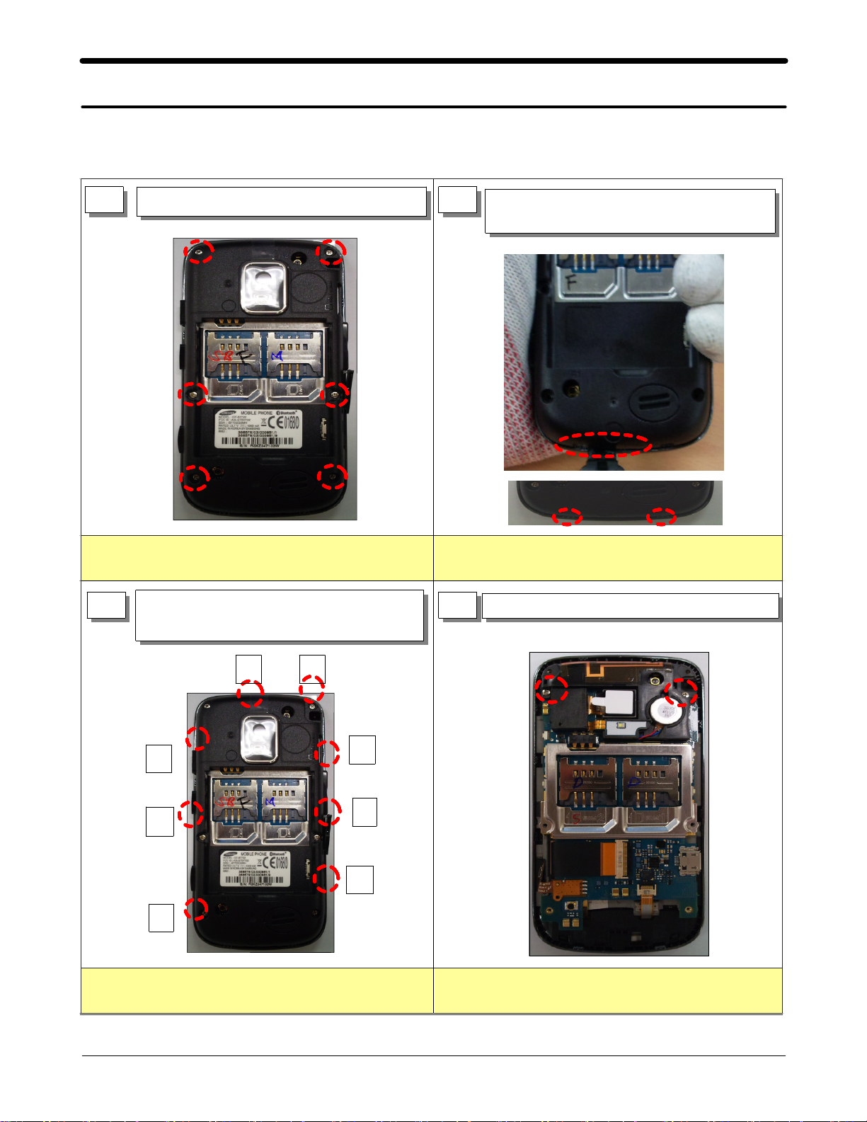
1
Be careful not to make scratch and molding damage Be careful not to make scratch and molding damage
Remove screws at6points.
1)
2
Put tools to set lower and disassemble
1)
from left to right.(2 POINTS)
3
below Order using tool.(8 POINTS)
4
Remove screws at2points..
1)
Separate rear after disassemble hook to
1)
⑦ ⑧
③
②
⑥
⑤
④
①
Be careful not to make scratch and molding damage Be careful not to damage to
SLAVE INTENNA
7-1
SAMSUNG Proprietary-Contents may change without notice
This Document can not be used without Samsung's authorization
Page 2
Level2Repair
7.
5
Fpcb to tweezers remove after Zip
1)
connector open.(2 POINTS)
detach side fpcb from lcd bracket
2)
1
1
2
Be careful to not to tear the FPCB.
1)
Catch and disassemble fpcb's hard part when
2)
disassembling tsp fpcb.
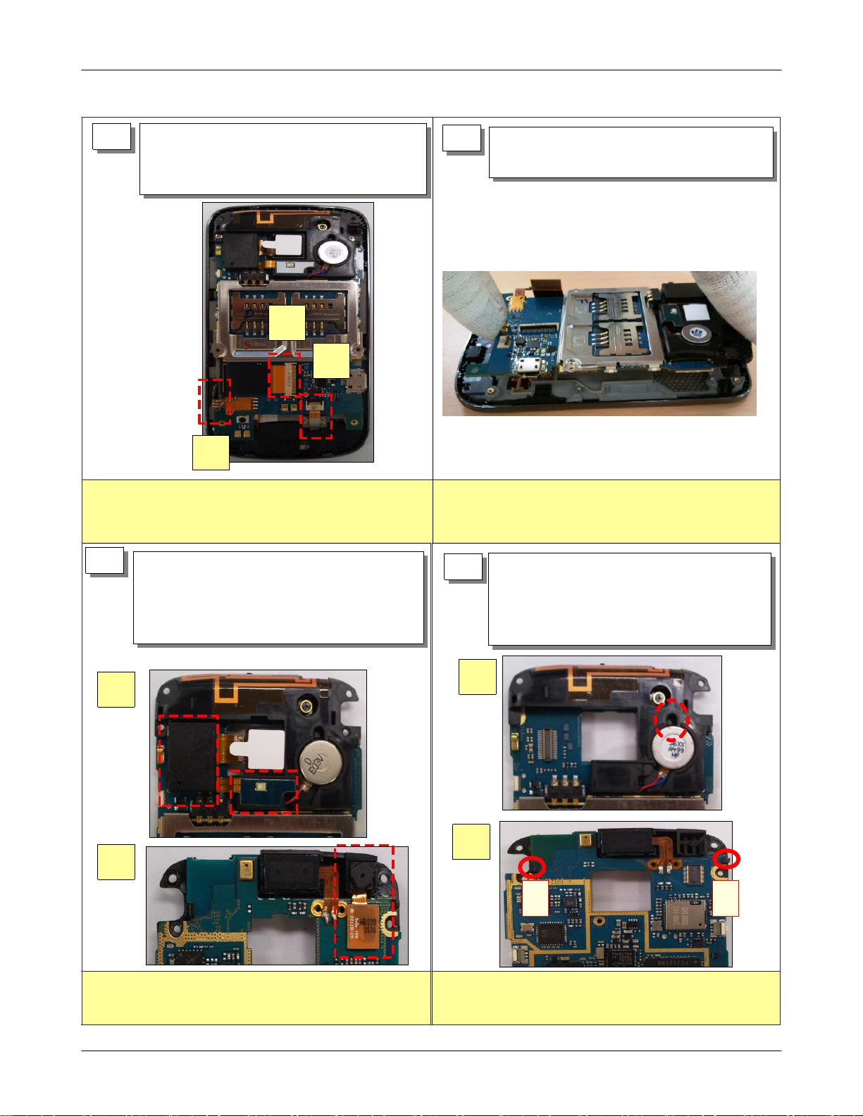
6
Be careful to not to tear the FPCB.
Take out vertically and separate main
1)
board.
7
Disassemble camera connector after taking
1)
out flash led to tweezers
Overturn board and disassemble cif camera
2)
connector of backside
8
Remove motor using disassembly hole.
1)
Catch board with both hand and
2)
disassemble intenna left/right hook part to
to2Order and separate intenna in board.
1
1
1
2
2
12
When separating connector and flash led, take care so that
fpcb is not damaged.
SAMSUNG Proprietary-Contents may change without notice
This Document can not be used without Samsung's authorization
When separating intenna, take care so that fpcb is not
damaged
7-2
Page 3

Level2Repair
7.
Take out conductivity sponge of bracket bottom
1)
9
left.
Remove bracket so as not to take to screw boss
2)
pointses after disassembling central left/right hook
4
point.
2
10
1) Disassemble lcd fpcb of bottom right.
1
Be careful of lcd fpcb damage when disassembling bracket
Disassemble subkey left/right hook and separate
1)
11
key unit
2
Be careful to not to tear the TSP FPCB.
Pushing front right and left side up and down
1)
12
end and disassemble front and lcd uni
Be careful to not to tear the LCD FPCB.
SAMSUNG Proprietary-Contents may change without notice
This Document can not be used without Samsung's authorization
Be careful lcd should not be twisted when twist
front
7-3
Page 4

Level2Repair
7.
7-1-2.
1
Assembly
Set to standards rib and pole after inserting
1)
setting sub key fpcb to front hole and attach.
2
Press after inserting sub key and confirm whether
2)
hook2pointses of backside were assembled.
Insert sub key at an angle at the bottom of front
1)
Be careful to not to tear the FPCB.
Assemble tsp fpcb after placing lcd unit depending
1)
3
on upper/lower4points groove on front that become
sub key placed.
Be careful to not to tear the TSP FPCB.
Confirm whether hook is inserted properly.
Careful of lcd fpcb insertion, and place to
1)
4
front lest should take bracket to screw boss
hole4pointses
Assemble central left/right hook2point
2)
1
Be careful of lcd fpcb damage when placing bracket.
2
7-4
SAMSUNG Proprietary-Contents may change without notice
This Document can not be used without Samsung's authorization
Page 5

5
Attach conductivity sponge on bottom left gnd fpcb.
1)
Attach insulation tape on bottom right tsp
2)
connector
Level2Repair
7.
6
Catch board with both hand and assemble
1)
intenna left/right hook part to1to
Order
Attach motor using at intenna hole.
2)
2
1
12
1
attached depending on base line for attachment
1)
Assemble camera connector after attach
1)
7
flash led to tweezers
Overturn board and assemble cif camera
2)
connector of backside
1
2
When assembling intenna, take care so that motor wire is
1)
not damaged.
Place main board vertically on front
1)
8
assay.
2
Be careful to not to tear the FPCB.
1)
Catch and disassemble fpcb's hard part when
2)
disassembling tsp fpcb.
SAMSUNG Proprietary-Contents may change without notice
This Document can not be used without Samsung's authorization
Be careful to not to tear the FPCB.
7-5
Page 6

Level2Repair
7.
Fpcb to tweezers insert after Zip
1)
9
connector open.(2 POINTS)
Attach side fpcb from lcd bracket
2)
1
2
Be careful to not to tear the FPCB.
1)
Catch and assemble fpcb's hard part when
2)
assembling tsp fpcb.
10
Torque : 1.1
Assemble screws at2points..
1)
1
Be careful not to damage to
SLAVE INTENNA
11
Assemble rear after assemble hook to
1)
below Order.(8 POINTS)
①
②
③
④
⑦
⑧
Torque : 1.2
⑤
⑥
12
Assemble screws at6points.
1)
Be careful not to make scratch and molding damage Be careful not to make scratch and molding damage
7-6
SAMSUNG Proprietary-Contents may change without notice
This Document can not be used without Samsung's authorization
 Loading...