

Page 1
Level
7.
Disassembly and assembly Instructions
7-1.
Repair
2
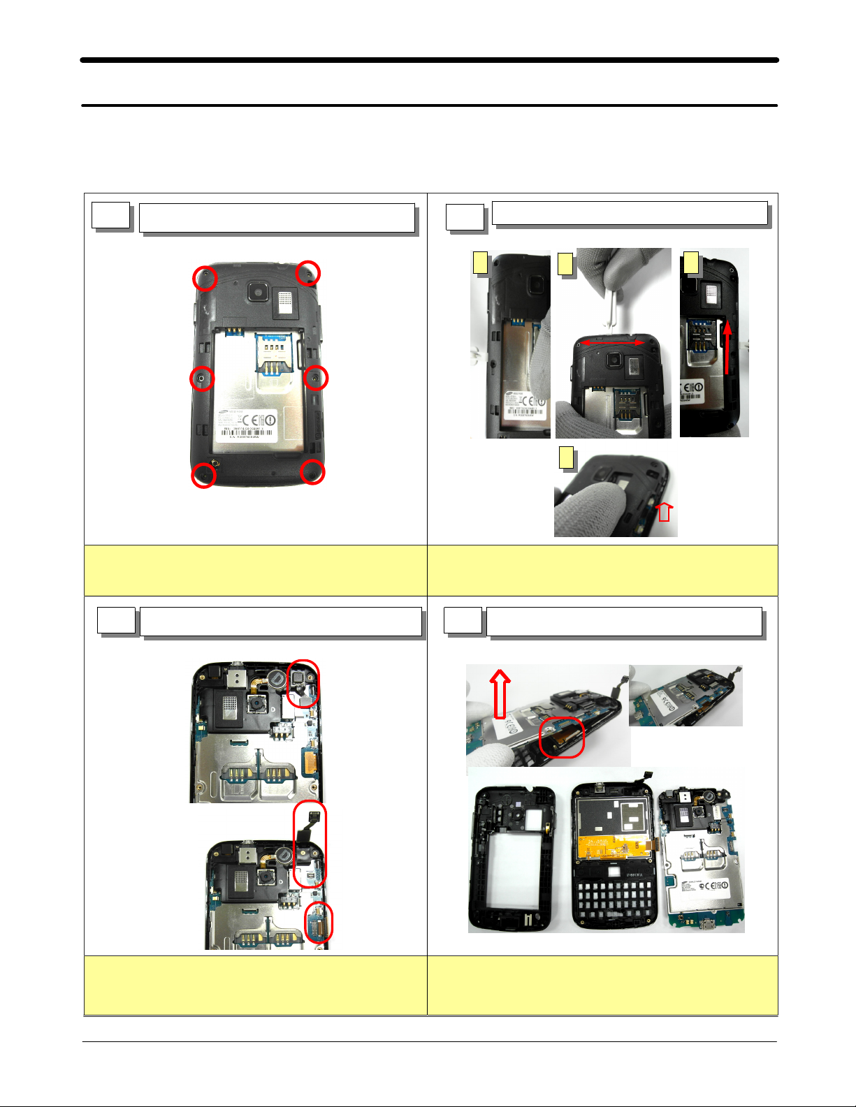
7-1-1.
Unscrew6points on Rear Case.
Torque=1.2 kgf*cm)
(
Disassembly
1
Unscrew Rear Case
Separate the Rear Case
2
2 3
Separate Rear part corner using
decomposition tool.
a
1
4
3
Separate2connectors.
Separate2connectors from the PBA with care. Lift the Hook&Separate the PBA from Front Ass'y.
4
Separate the PBA from Front Ass'y.
7-1
SAMSUNG Proprietary-Contents may change without notice
This Document can not be used without Samsung's authorization
Page 2
Level2Repair
7.
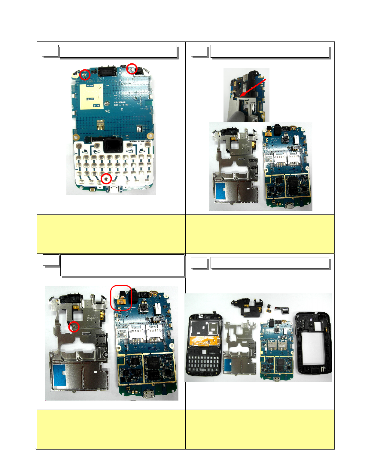
5
Unscrew PBA
6
Separate Shield Can
Unscrew4points on the PBA.
Torque=1.2 kgf*cm)
(
7
Unscrewapoint on the shield can.
SeparateaVGA camera from the PBA.
Separate the Shield Can.
END
8
7-2
SAMSUNG Proprietary-Contents may change without notice
This Document can not be used without Samsung's authorization
Page 3

Level2Repair
7.
1
3
assemble
READY
Assemble the Speaker Module.
And Screw4points on PBA.
Torque : 1.1 ~ 1.3 Kgf·cm , Size : 1.4*2.0
2
Assemble the VGA camera&shiled can.
Assemble the PBA to FRONT Ass'y.
4
7-1-2.
READY Insert the Shield-Can on PBA
Screw4points on the PBA.
Assemble the Optical Track Pad to PBA
Close a connector lever & Attach a tape on connector.
.
SAMSUNG Proprietary-Contents may change without notice
This Document can not be used without Samsung's authorization
Place PBA carefully on hook.
7-3
Page 4

Level2Repair
7.
5
Assemble the PBA to FRONT Ass'y.
6
Assemble the Rear Case
Assemble the LCD Connector&TSP Connector. Assemble the Rear Case to FRONT Ass'y.
Screw REAR6-point
7
Torque
:1.0~1.2
Kgf·cm/Size
:1.4*3.5
Land REAR on PBA and screw REAR6-point.
Torque=1.2 kgf*cm)
(
7-4
SAMSUNG Proprietary-Contents may change without notice
This Document can not be used without Samsung's authorization
 Loading...