

Page 1
11. Disassembly and Assembly Instructions
11-1 Disassembly
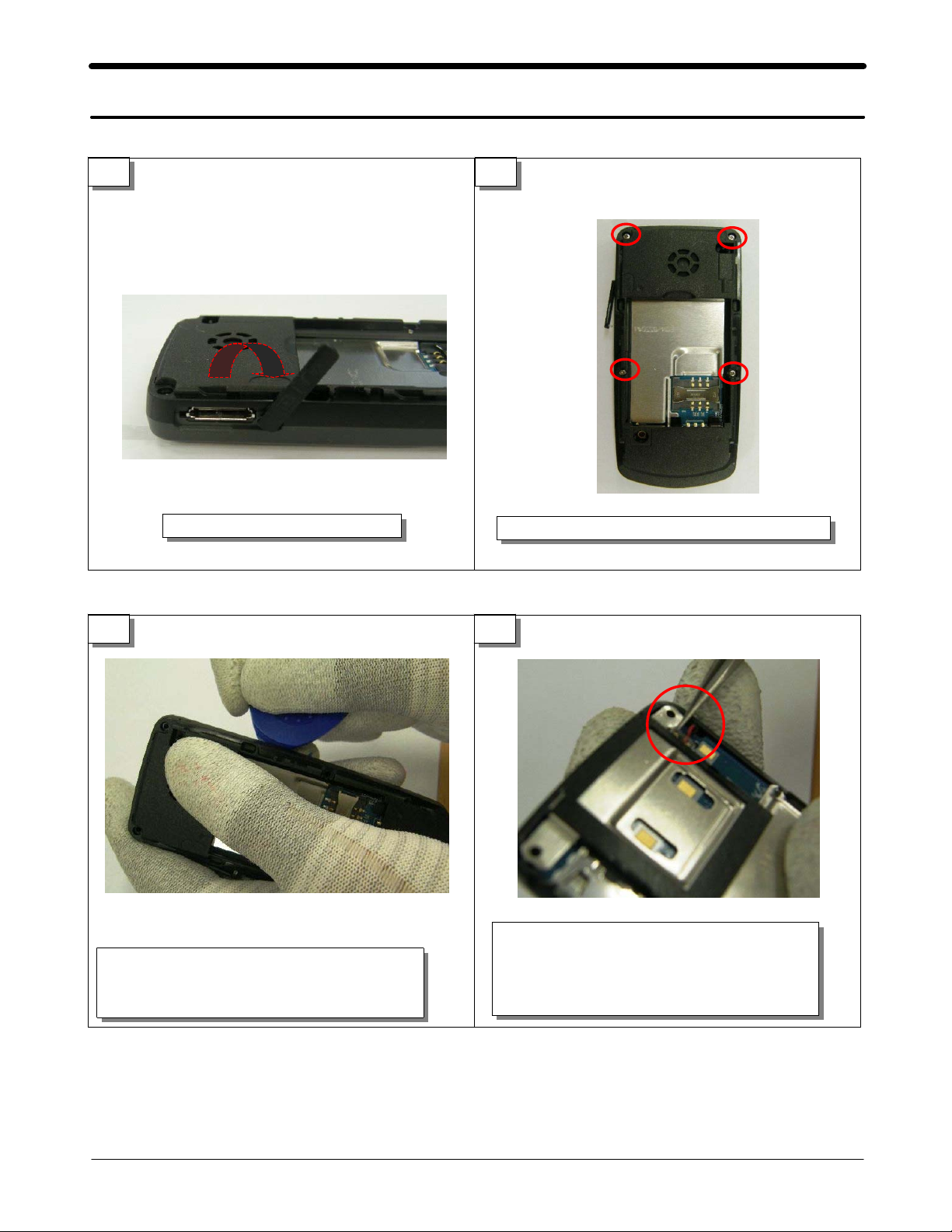
1 2
Open the charger socket cover.
3 4
Disjoint REAR's left, right HOOK using a
decomposition tool.
Release SCREW 4POINT at REAR.
Remove receiver connector of the PBA right
side top portion using round tweezers.
(That pay attention to damage at connector
exclusion.)
11-1
SAMSUNG Proprietary-Contents may change without notice
This Document can not be used without Samsung's authorization
Page 2
Disassembly and Assembly Instructions
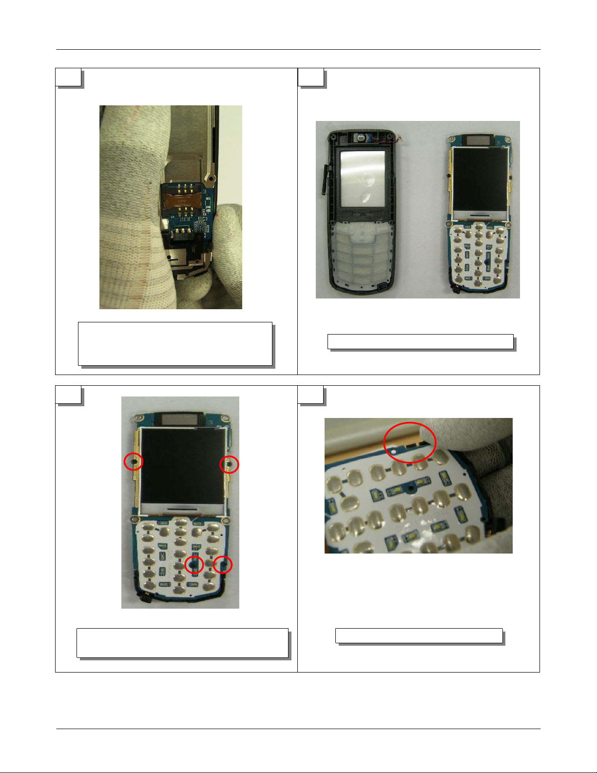
5 6
Disjoint FRONT's left, right PBA fixing
HOOK.
(That pay attention to parts damage.)
7 8
FRONT & PBA
Disjoint shield can after release SCREW
4 POINT.
SAMSUNG Proprietary-Contents may change without notice
This Document can not be used without Samsung's authorization
Separate Intenna fixing HOOK in PBA.
11-2
Page 3

Disassembly and Assembly Instructions
9
Sectioning PBA.
11-3
SAMSUNG Proprietary-Contents may change without notice
This Document can not be used without Samsung's authorization
Page 4

Disassembly and Assembly Instructions
11-2 Assembly
1 2
Drivers shield can screw 3 POINT and
fixes shield can.
Assembles and fixes Intenna HOOK
on right and left of PBA lower
side.
3
Drivers antenna screw 1 POINT.
4
Insert PBA's MIC ASS' Y to FRONT's MIC guide
HOLE. After that, puts down to front and
fixes PBA.
11-4
SAMSUNG Proprietary-Contents may change without notice
This Document can not be used without Samsung's authorization
Page 5

5 6
Insert receiver connector.
(When insert connector,
that pay attention to damage.)
Disassembly and Assembly Instructions
Assemble FRONT and REAR from HOOK of lower
side.
7 8
Assemble top portion HOOK after lower side
assembly.
Assemble the last HOOK on the bottom of
the rear.
11-5
SAMSUNG Proprietary-Contents may change without notice
This Document can not be used without Samsung's authorization
Page 6

Disassembly and Assembly Instructions
9
Assembled SET
11-6
SAMSUNG Proprietary-Contents may change without notice
This Document can not be used without Samsung's authorization
 Loading...