

Page 1
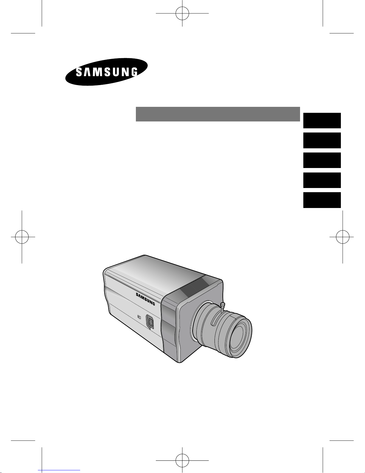
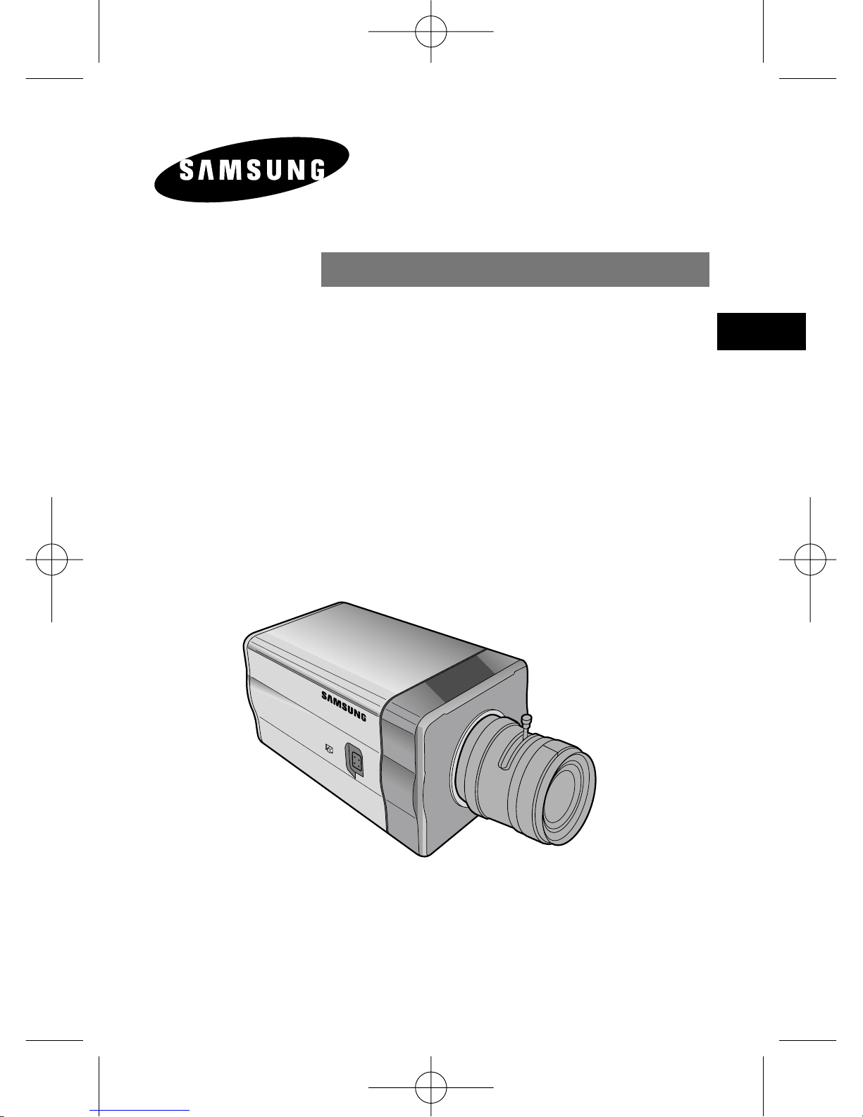
DAY/NIGHT COLOR CAMERA
SCC-B2303(P)/B2003P
SCC-B2307P/B2007P
User’s Manual
E
D
F
Es
I
00424A SCC-B2307P-eng 4/7/05 9:11 PM ˘`1
Page 2
E
2
CAUTION: TO REDUCE THE
RISK OF ELECTRIC SHOCK,
DO NOT REMOVE REAR
COVER. NO USER
SERVICEABLE PARTS INSIDE.
REFER TO QUALIFIED
SERVICE PERSONNEL.
To prevent damage which may result in fire or electric shock hazard,
do not expose this appliance to rain or moisture.
This device complies with part 15 of the FCC Rules. Operation is
subject to the following two conditions.
1) This device may not cause harmful interference, and
2) This device must accept any interference that may cause undesired
operation.
CAUTION:
Danger of explosion if battery is incorrectly replaced.
Replace only with the same or equivalent type recommended by the
manufacturer.
Dispose of used batteries according to the manufacturer’s instructions.
This symbol indicates
high voltage is present
inside. It is dangerous to
make any kind of contact
with any inside part of
this product.
This symbol alerts you
that important literature
concerning operation and
maintenance has been
included with this
product.
CAUTION
RISK OF ELECTRIC
SHOCK DO NOT OPEN
00424A SCC-B2307P-eng 4/7/05 9:11 PM ˘`2
Page 3
3
Important Safety Instructions
E
1. Read these instructions.
2. Keep these instructions.
3. Heed all warnings.
4. Follow all instructions.
5. Do not use this apparatus near water.
6. Clean only with dry cloth.
7. Do not block any ventilation openings. Install in accordance
with the manufacturer’s instructions.
8. Do not install near any heat sources such as radiators, heat
registers, or other apparatus (including amplifiers) that produce
heat.
9. Do not defeat the safety purpose of the polarized or groundingtype plug. A polarized plug has two blades with one wider than
the other. A grounding type plug has two blades and a third
grounding prong. The wide blade or the third prong are
provided for your safety. If the provided plug does not fit into
your outlet, consult an electrician for replacement of the
obsolete outlet.
10. Protect the power cord from being from being walked on or
pinched particularly at plugs, convenience receptacles, and the
point where they exit from the apparatus.
11. Only use attachments/accessories specified by the
manufacturer.
12. Use only with cart, stand, tripod, bracket, or table specified by
the manufacturer, or sold with the apparatus. When a used,
caution when moving the cart/apparatus combination to avoid
injury from tip-over.
13. Unplug this apparatus. When a cart is used, use caution when
moving the cart/apparatus combination to avoid injury from tipover.
14. Refer all servicing to qualified service personnel. Servicing is
required when the apparatus has been damaged in any way,
such as power-supply cord or plug is damaged, liquid has been
spilled or objects have fallen into the apparatus, the apparatus
has been exposed to rain or moisture, does not operate
normally, or been dropped.
00424A SCC-B2307P-eng 4/7/05 9:11 PM ˘`3
Page 4

E
4
Contents
Chapter 1 Introduction ........................................................ 5
Chapter 2 Special Features ............................................. 6
Chapter 3 Part Names and Functions ............................... 7
Chapter 4 Installation .......................................................... 12
Cautions for Installation and Use .......................13
Connecting Automatic Shutter Lens Connector
........... 14
Fixing Lens and Adjusting Lens Selection Switch
....... 15
Adjusting Back Focus ........................................ 16
Connecting Cables ............................................ 18
Chapter 5 Camera Set-Up ................................................. 20
Appendix Product Specification ........................................ 39
NOTE: Avoid aiming the camera directly towards extremely bright
objects such as the sun, as this may damage the CCD image sensor.
00424A SCC-B2307P-eng 4/7/05 9:11 PM ˘`4
Page 5
5
Chapter 1 Introduction
E
The DAY/NIGHT Camera operates in a color mode in an the
illumination over the standard value and otherwise in B/W mode by
deleting the IR Cut function, which contributes to the improvement
of sensitivity so that it is called a low illumination camera which is
able to identify objects in a dark area. Meanwhile, it has
incorporated a Sense Up function owing to a low speed shutter and
a field accumulation method to improve its low illumination feature
prominently.
The DAY/NIGHT Camera is mostly used in dark places like
basement parking lots with a comparatively low illumination. In
daytime, it provides a color screen of high density with a horizontal
resolution of 480, and, at night, it utilizes the DAY/NIGHT function
as well as the Sense Up function to identify objects. In same cases,
you may use this camera in relation to the infrared ray emission
equipment additionally.
[DAY/NIGHT]
It is a function of a color camera to delete the fiter with the
IR Cut function in an illumination below the standard value
so that it has a better sensitivity.
00424A SCC-B2307P-eng 4/7/05 9:11 PM ˘`5
Page 6
6
Chapter 2 Special Features
E
High Sensitivity
It has an up-to-date 1/3" Super(EXview)-HAD IT CCD for an image of high
sensitivity.
Low Illumination Function
It has both a low illumination function and DAY/NIGHT function based on
digital signal technology in order to operate in the worst environment
without light.
Digital Zoom Function
It has a digital zoom function for a 10 time enlargement as a maximum. (If
you turn the PIP function to the Digital Zoom mode, the whole screen will
be displayed as a PIP screen.
Superior Back Light Adjustment Function
In case the object has a bright illumination or sunlight behind it, this camera
adjusts the image shaded by the back light for clear photographs.
Digital Power Supply Synchronization Method
The Full Digital Method Line Lock is realized in this camera, which adjusts
the vertical camera synchronization directly to improve controllability and
reliability of the camera.
Resolution
It realizes high resolution resulting from full digital image processing
supported by a state-of-art digital signal technology.
Output Signal Setting
It is able to reverse video output signals and set both a vertical and
horizontal profile.
00424A SCC-B2307P-eng 4/7/05 9:11 PM ˘`6
Page 7
7
Chapter 3 Part Names and Functions
E
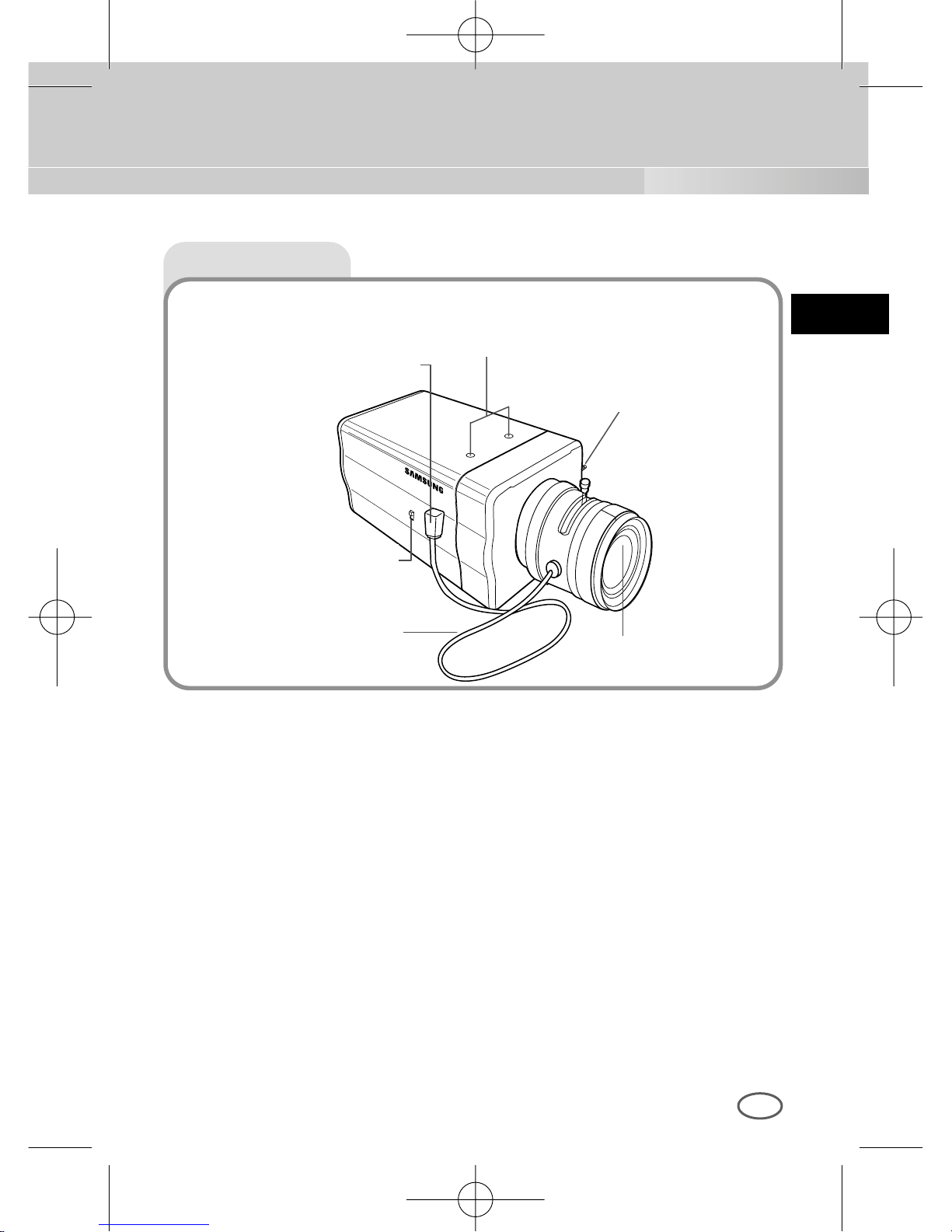
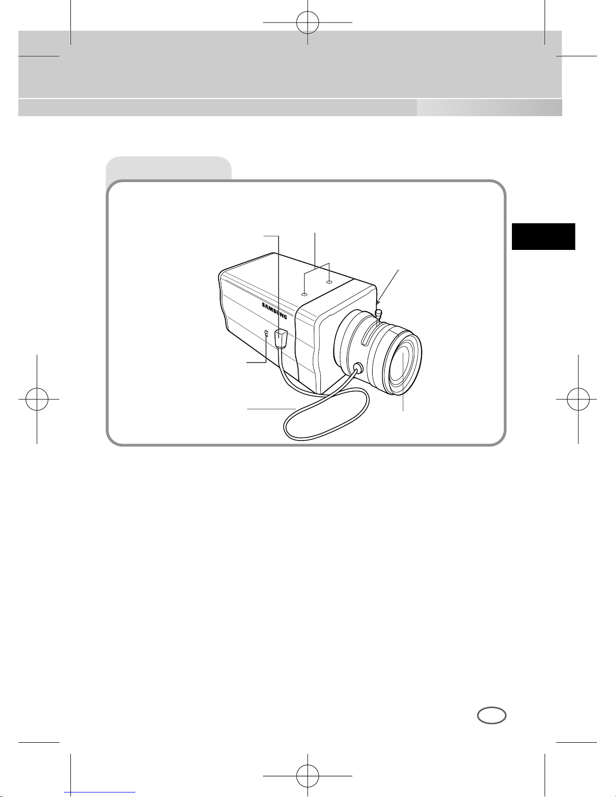
Side View
Mount Adapter Fixing Groove
This groove is used for screwing the mount adapter, a part of the bracket
where the camera will be installed.
Camera Lens(Option)
This lens is installed in the camera.
* A camera lens with a stained surface should be cleaned softly with a lens
tissue or ethanol painted cotton cloth.
Auto Iris Lens Connector
This connector provides the automatic shutter lens with power supply,
control signal, video signal, or DC signal necessary for the control of the
lens shutter
Automatic Shutter
Lens Control Cable
ALC Lens
Selection Switch
Auto Iris Lens
Connector
Mount Adapter Fixing
Groove
Back Focus
Control Bar
Camera Lens
00424A SCC-B2307P-eng 4/7/05 9:11 PM ˘`7
Page 8
E
8
Auto Iris Lens Control Cable
This cable transmits the control signal from the camera to control the lens
shutter.
Back Focus Control Bar
It controls the back focus.
ALC Lens Setting Switch
This switch sets the Auto Iris lens type for use.
DC : When you attach an Auto Iris lens requiring the DC control signal,
please put this switch in the DC position.
VIDEO : When you attach an Auto Iris lens requiring the video control
signal, please put this switch in the VIDEO position.
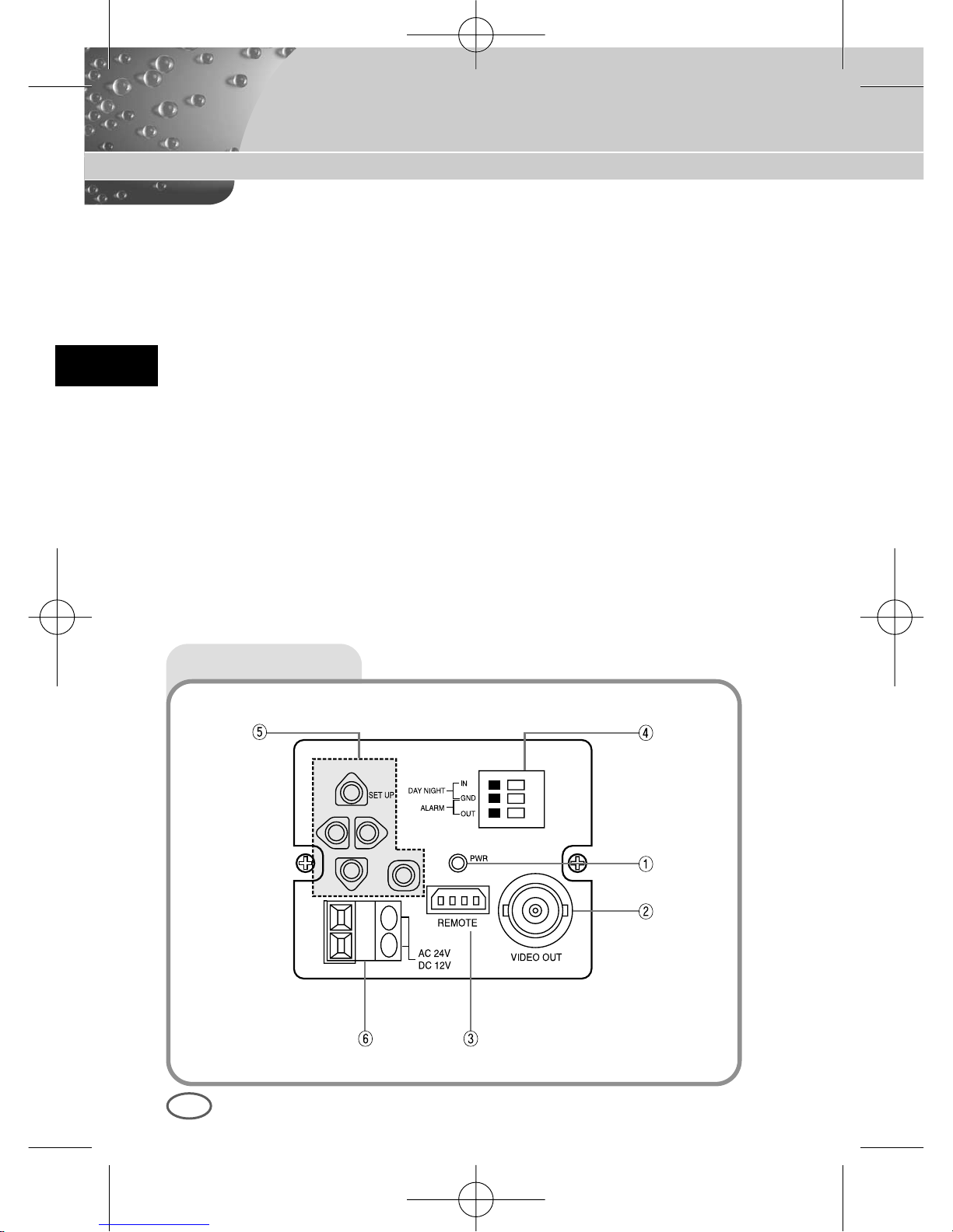
Rear View
00424A SCC-B2307P-eng 4/7/05 9:11 PM ˘`8
Page 9
E
9
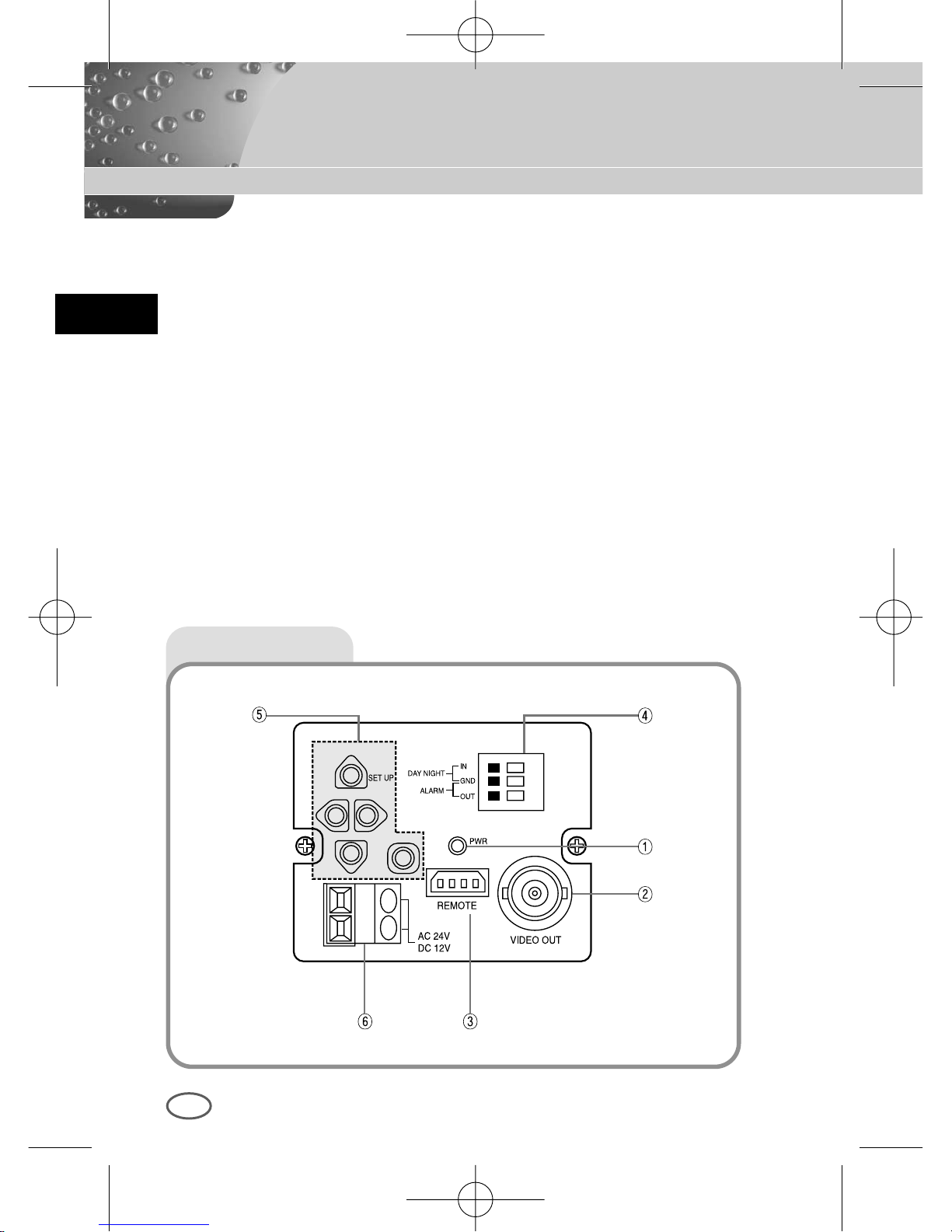
① Power Display LED
When the camera is supplied with power, LED is on.
➁ Video Output Terminal
The monitor video input terminal is connected with this terminal through
which the camera video signal comes out.
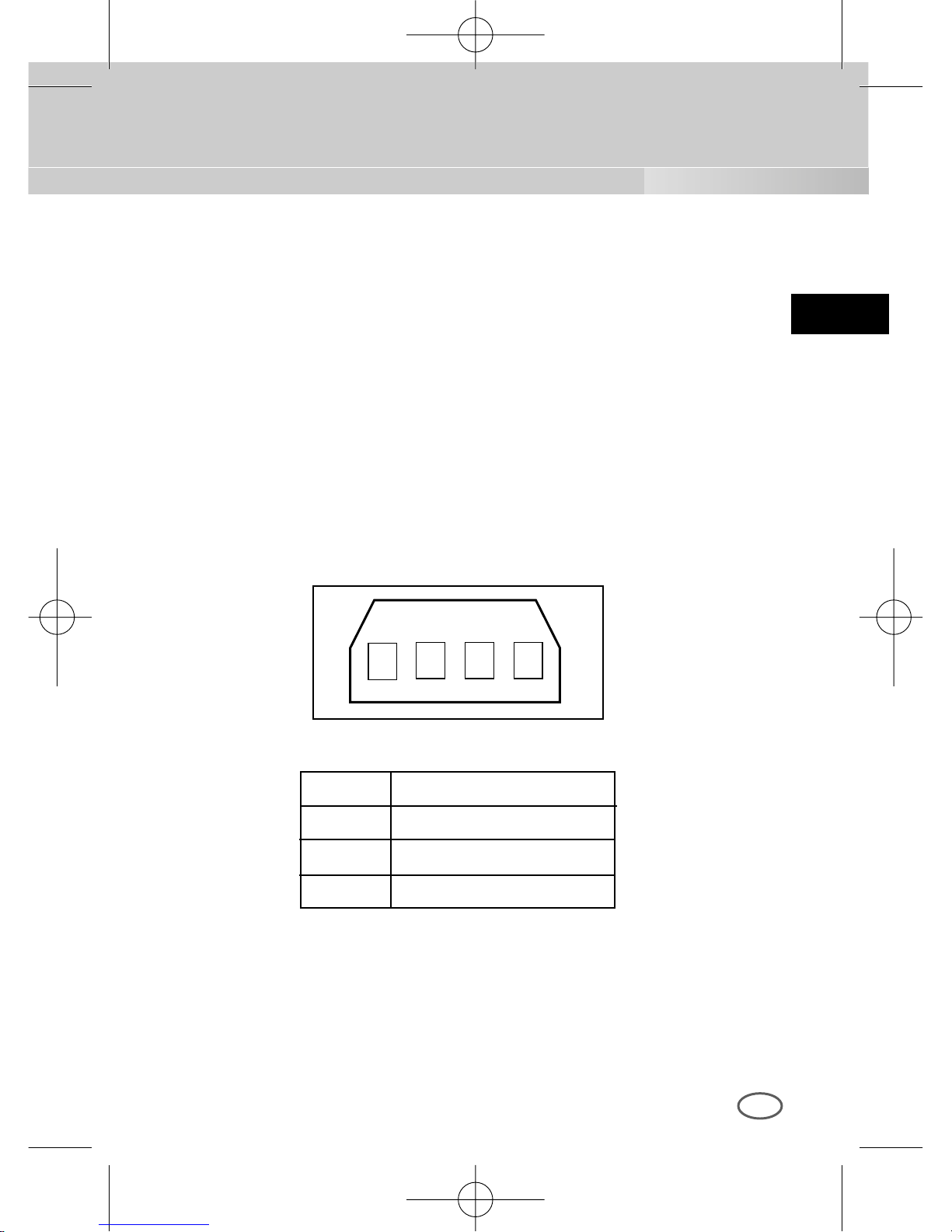
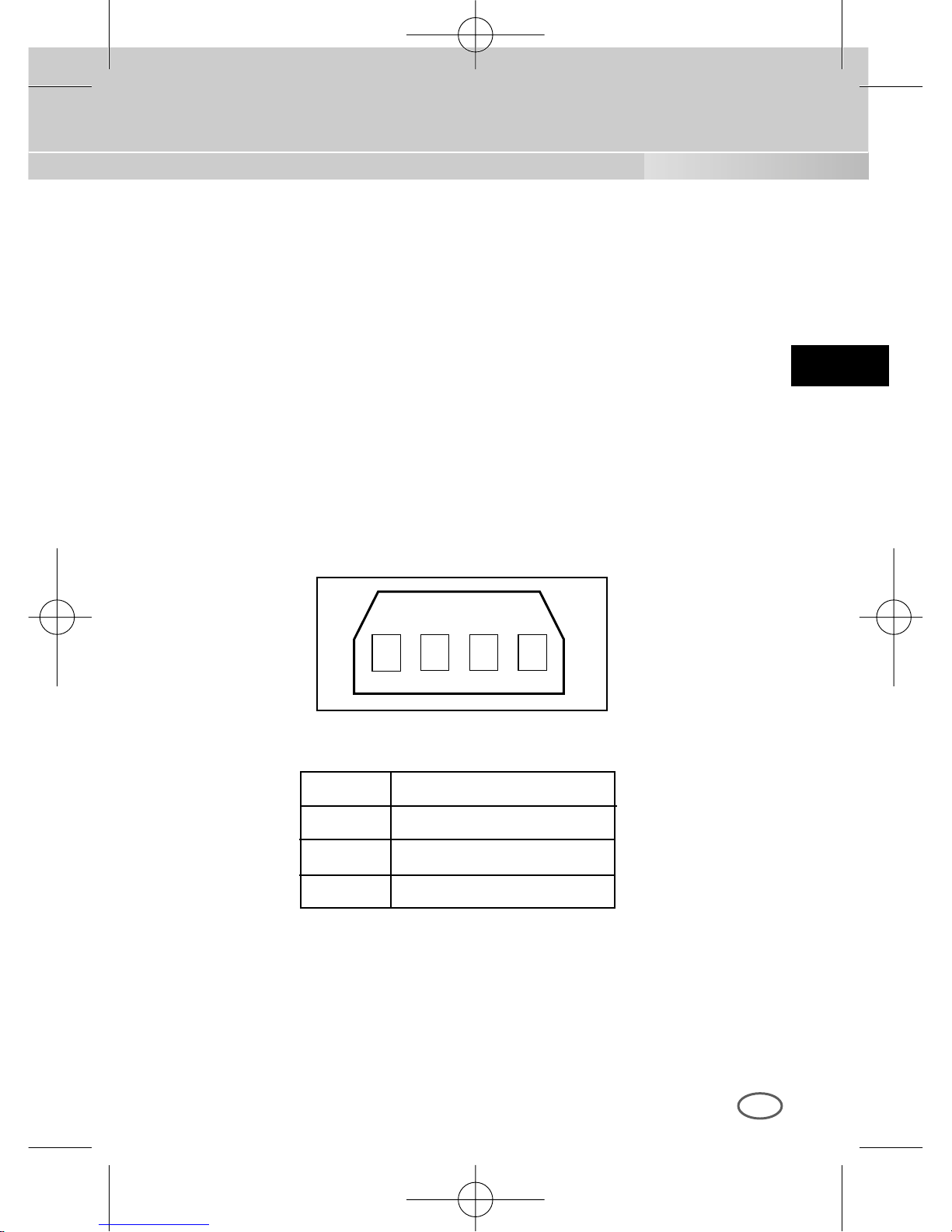
➂ Remote Input Terminal(RS-232)
This terminal is used for camera control at the production plant.
1
2 3 4
1 TXD
2 RXD
3 +5V
4 GND
00424A SCC-B2307P-eng 4/7/05 9:11 PM ˘`9
Page 10
E
10
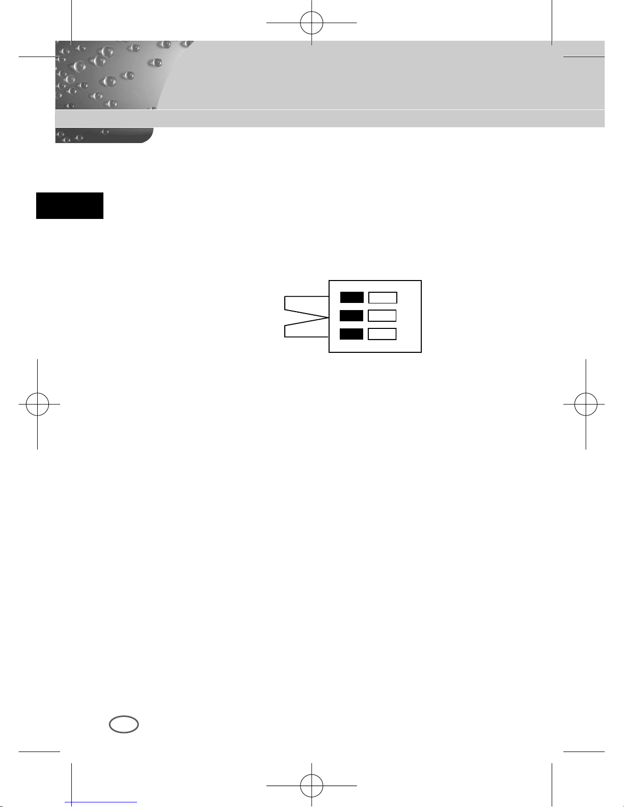
➃ DAY/NIGHT External Signal Input & Alarm Signal Output
This is a function to receive the external DAY/NIGHT signal from the
sensor(option) and convert the signal into BW. The MOTION DET
function generates an alarm signal when a movement is detected.
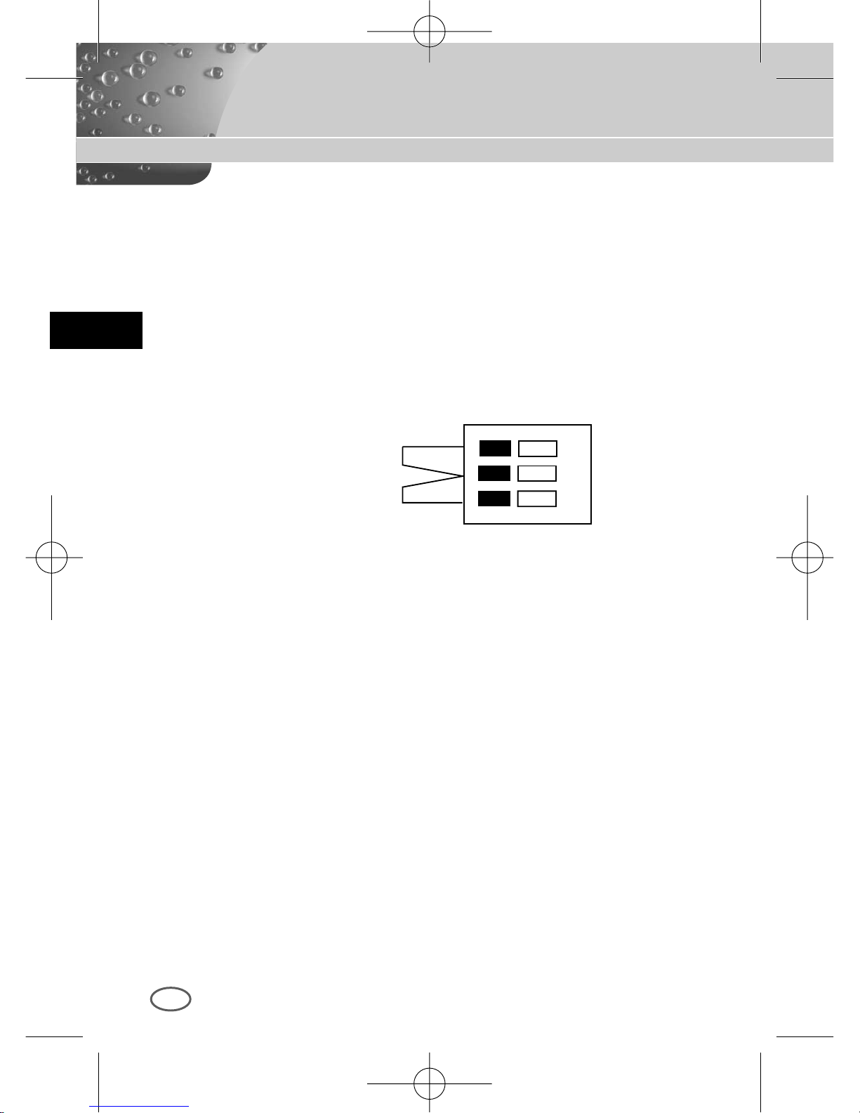
①
➁
DAY/NIGHT IN
GND
ALARM OUT
Connect an external sensor to the DAY/NIGHT terminal as shown in ① then
connect any external device such as a buzzer or lamp to the ALARM
terminal as shown in ➁.
The ALARM output terminal is an open collector with the following capacity:
DC 16V and 100mA.
OFF : Open contact
ON : Below 100mA
The DAY/NIGHT input terminal has the input of DC 5V pull-up and over
0.2mA.
OFF : Open contact
ON : Closed contact
00424A SCC-B2307P-eng 4/7/05 9:11 PM ˘`10
Page 11
E
11
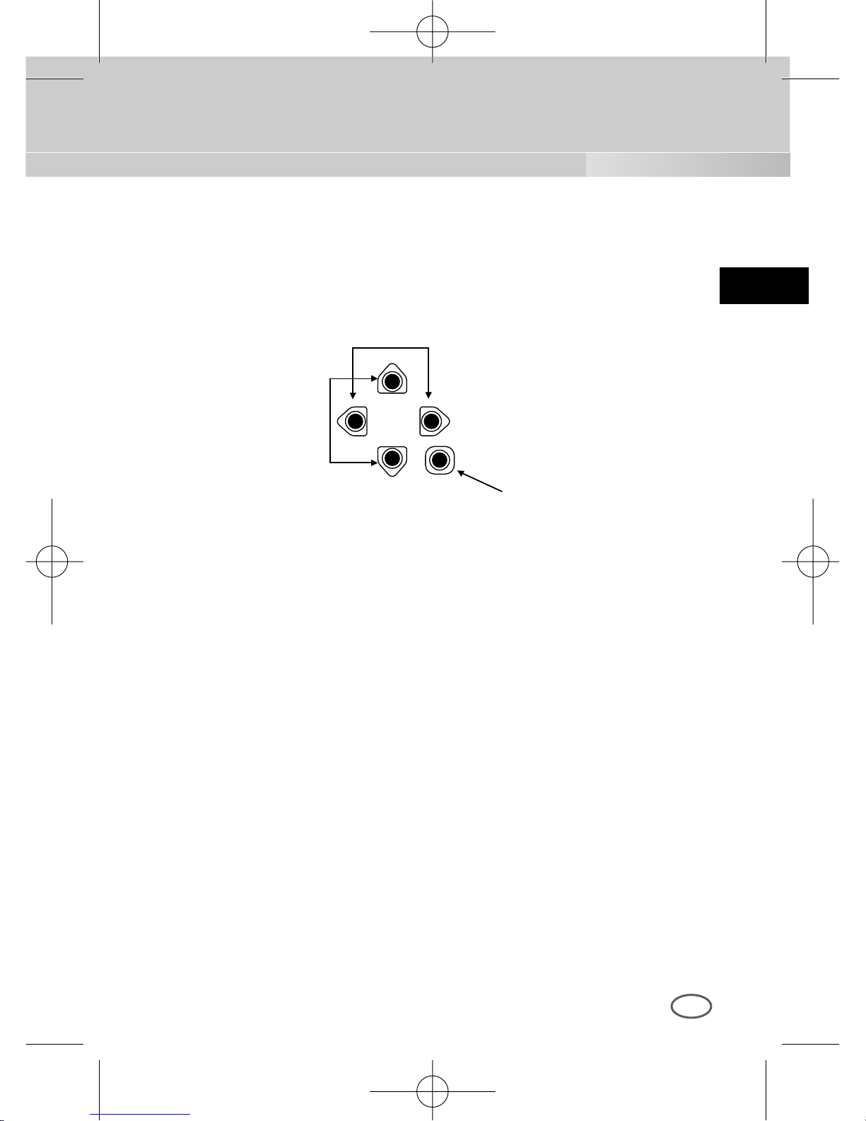
⑤ Camera Operation Switch(Setup Switch)
The function of the camera operation switch changes depending on
whether the camera is currently in the usual operation mode(No setup
menu is seen on the screen) or the setup menu mode.
In the usual operation mode
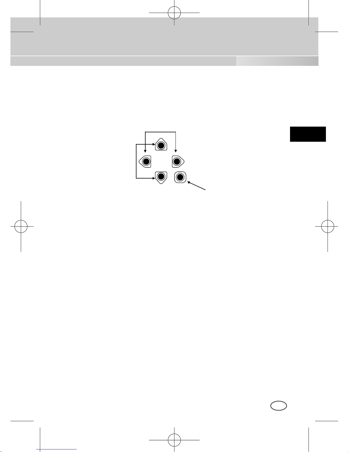
[LEFT/RIGHT] key : Press key for about 2 seconds and the
menu comes out to control the DC IRIS level. The
[LEFT] key raises the level and the [RIGHT] key
lowers the level.
[ENTER] key : It is used to enter the Setup menu.(Press it about 2
seconds.)
In the setup menu mode
[UP/DOWN] key : These keys move up or down the cursor.
[LEFT/RIGHT] key : These keys move the cursor to the left or right or
identify the values sequentially which can be
assigned in each setup menu.
[ENTER] key : It is used to enter a sub-menu of a setup menu by
clicking the setup menu or to set the current value.
➅ Power Connection Port
This port is connected to the power(adapter) cable.
[LEFT/RIGHT] key
[ENTER] key
[UP/DOWN] key
00424A SCC-B2307P-eng 4/7/05 9:11 PM ˘`11
Page 12
12
Chapter 4 Installation
E
This chapter describes what should be checked before installation, how to
set the installation environment, and what should be done during
installation. Then, it describes how to install the camera and connect the
cable in actual circumstances.
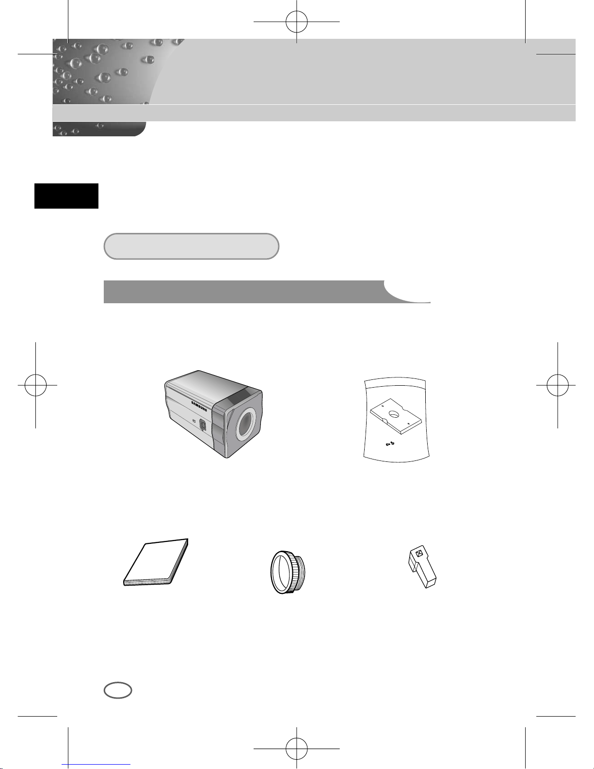
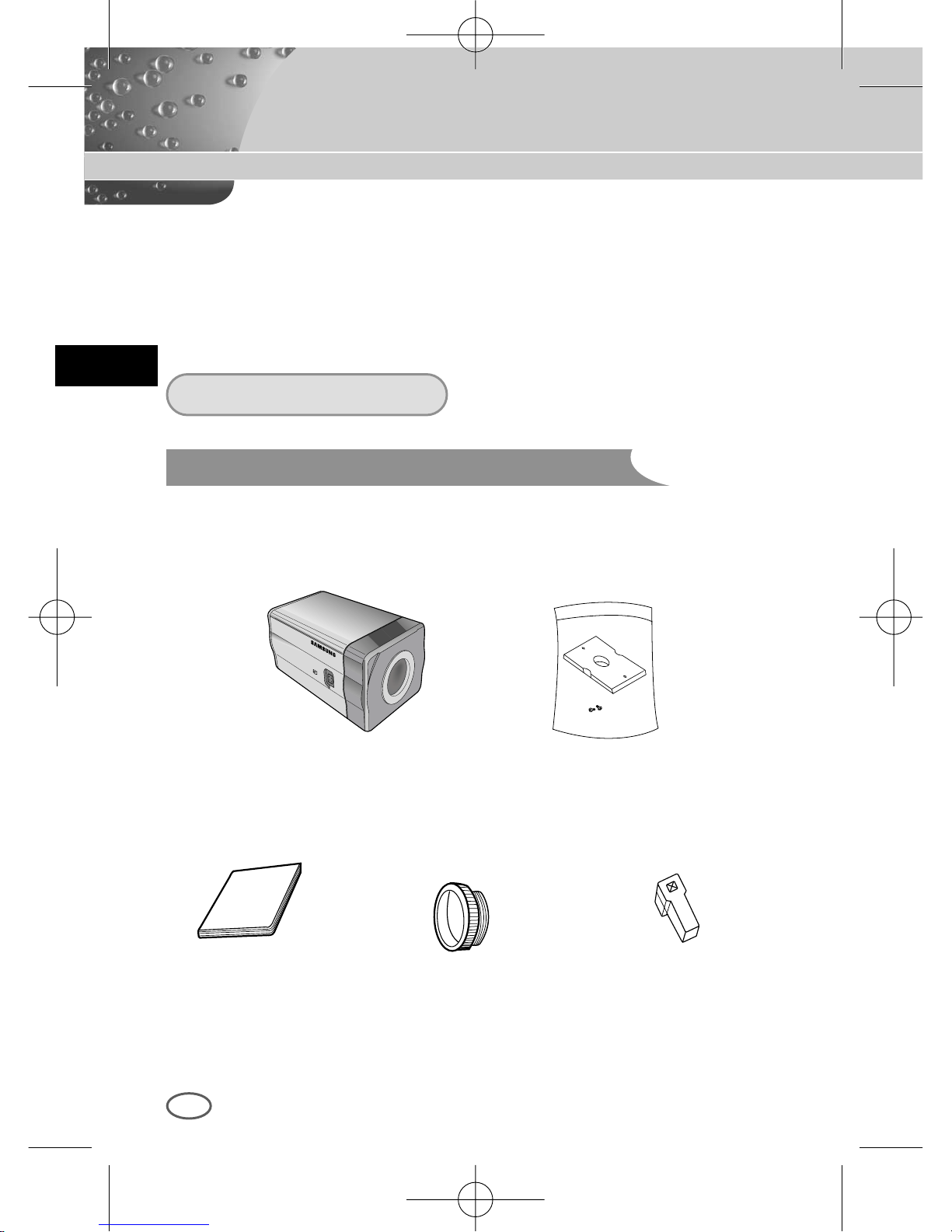
Be sure to check if the following items are included in the package.
Before Installation
Checking the contents of the package
Camera Camera Holder(Mount)
C Mount Adapter Auto Iris
Lens Connector
User's Manual
00424A SCC-B2307P-eng 4/7/05 9:11 PM ˘`12
Page 13
E
13
① Do not disassemble the camera on your own.
➁ Be careful when handling the camera at all times. Do not strike the
camera with your fists or shake it. The camera should be stored and
treated with care to avoid any damage.
➂ Do not put or operate the camera in rain or wet places.
➃ Do not scrub the camera body with rough sandpaper when it is stained.
Please use a dry cloth at all times.
⑤ Put the camera in a cool area free from direct light. Otherwise, the
camera may be damaged.
What should be done during installation and use
00424A SCC-B2307P-eng 4/7/05 9:11 PM ˘`13
Page 14
E
14
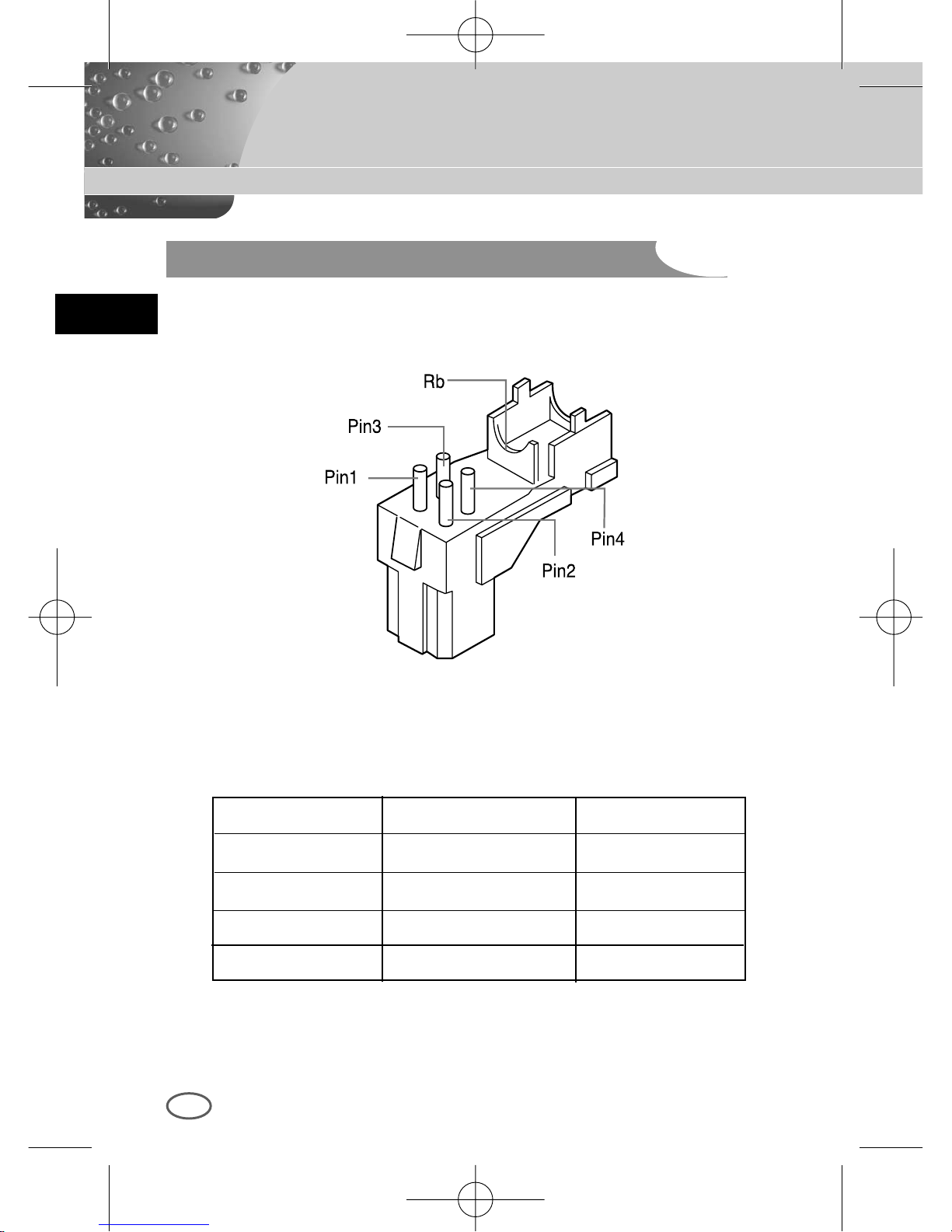
Connecting Auto Iris Lens Connector
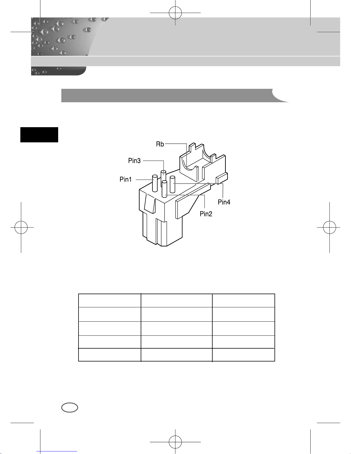
Prepare the Auto Iris lens connector, a camera auxiliary, as follows :
Connect each uncovered shutter control cable wire to the Auto Iris lens
connector as follows.
Pin No. DC Control Type VIDEO Control Type
1 Damp(-) Power (+12V)
2 Damp(+) N/A
3 Drive(+) VIDEO Signal
4 Drive(-) GROUND
00424A SCC-B2307P-eng 4/7/05 9:11 PM ˘`14
Page 15
E
15
Installation
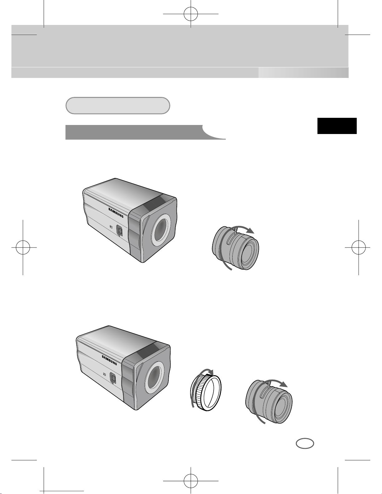
Lens Fixing
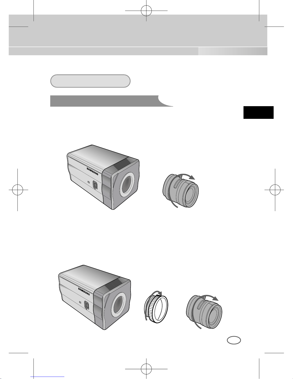
In case of CS lenses
Turn the CS lens clockwise until it is fixed as shown as follows.
In case of C lenses
Turn the C-mount adapter clockwise to fix it. Then turn the C lens
clockwise until it is fixed as follows.
CS lens
C lens
00424A SCC-B2307P-eng 4/7/05 9:12 PM ˘`15
Page 16
E
16
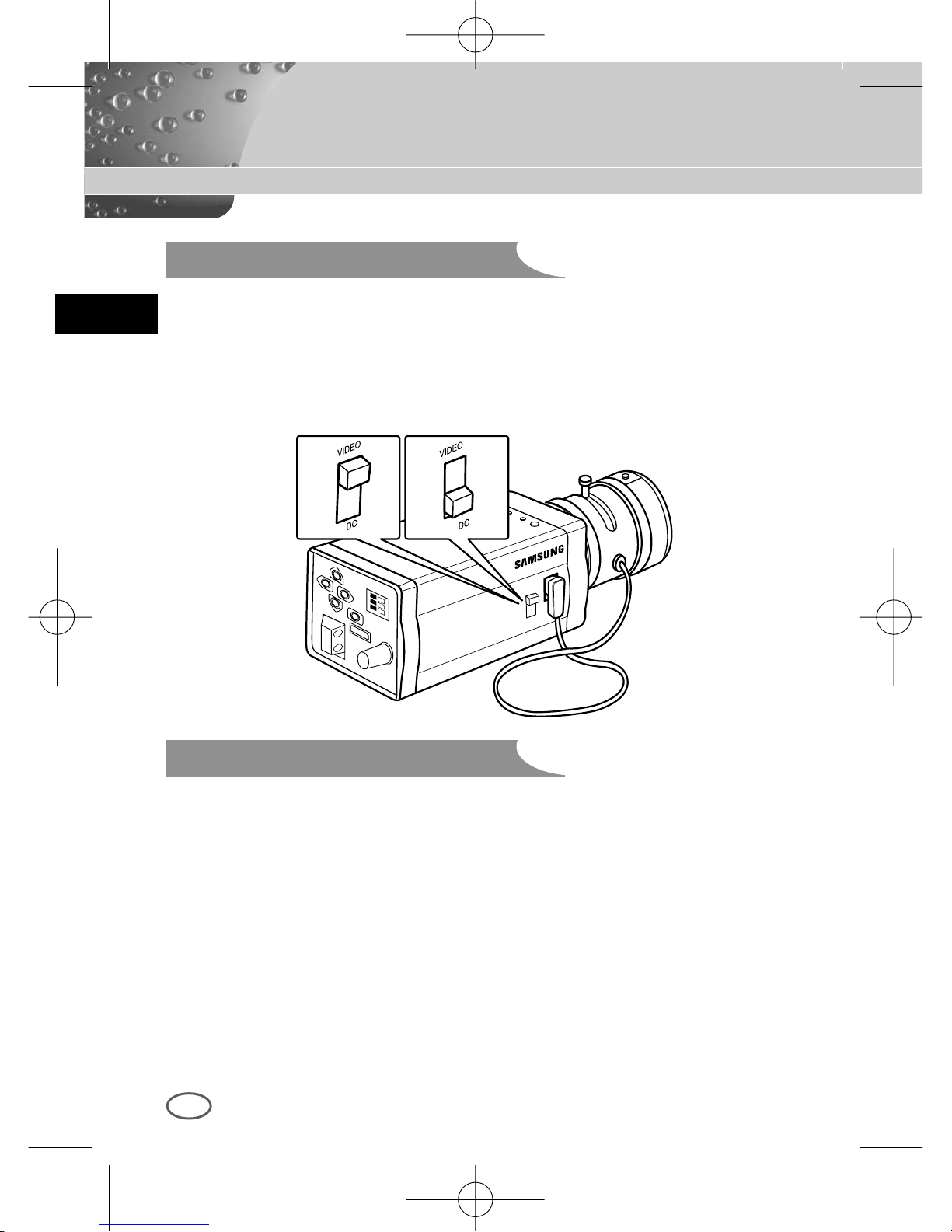
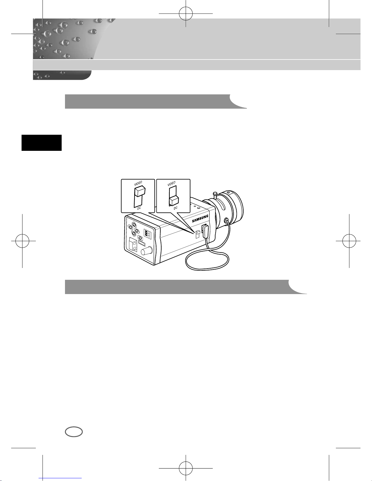
Setting Switch Control
Back Focus Adjustment
You should change the position of the lens setting switch on the side of the
camera according to the lens type. Depending on whether you fixed the DC
control type Auto Iris lens or video control type automatic shutter lens, you
should put the switch in "DC" or "VIDEO" position respectively.
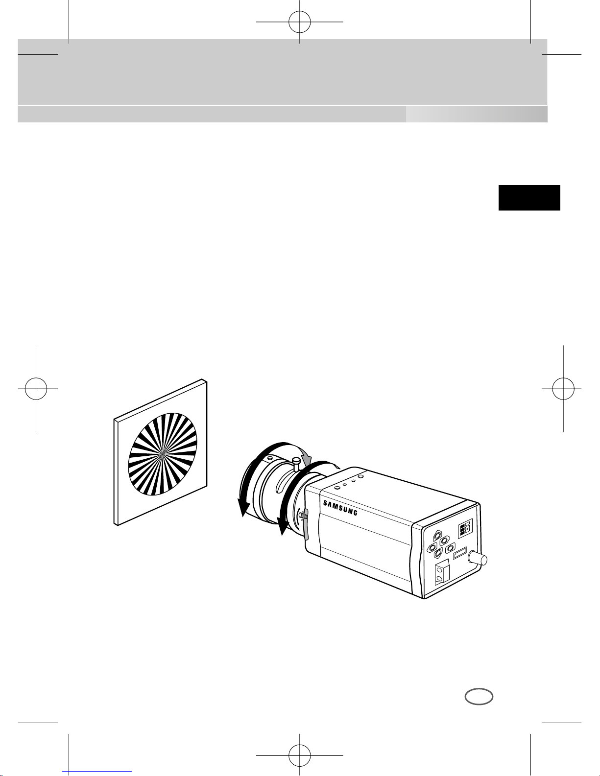
The camera back focus is adjusted at the plant before delivery, but some
lenses are out of focus though the number differs in types. If it's the case,
you should make the back focus adjustment as follows. First, this is the
back focus adjustment procedure for fixed focus lenses.
Lenses without zoom function
① Image an object with high resolution(letticed) at more than 10m distance
and put the lens focus ring in the infinite(
∞
) position.
➁ Rotate the BACK FOCUS control bar until the object is seen best.
➂ Tighten the BACK FOCUS control bar fixing screw.
00424A SCC-B2307P-eng 4/7/05 9:12 PM ˘`16
Page 17
E
17
Lenses with zoom function
① Image an object with high resolution(letticed) at a distance of 3 to 5 m
and zoom in the lens as close to TELE as possible. Then adjust the lens
focus bar until the object is seen best.
➁ Zoom in the lens as close to WIDE as possible and adjust the BACK
FOCUS adjustment bar until the object is seen best.
➂ Repeat from ① to ➁ above 2 or 3 times until the focus on the ZOOM
TELE side is in line with that on the ZOOM WIDE side.
00424A SCC-B2307P-eng 4/7/05 9:12 PM ˘`17
Page 18
E
18
Connecting Cables and Checking Operation
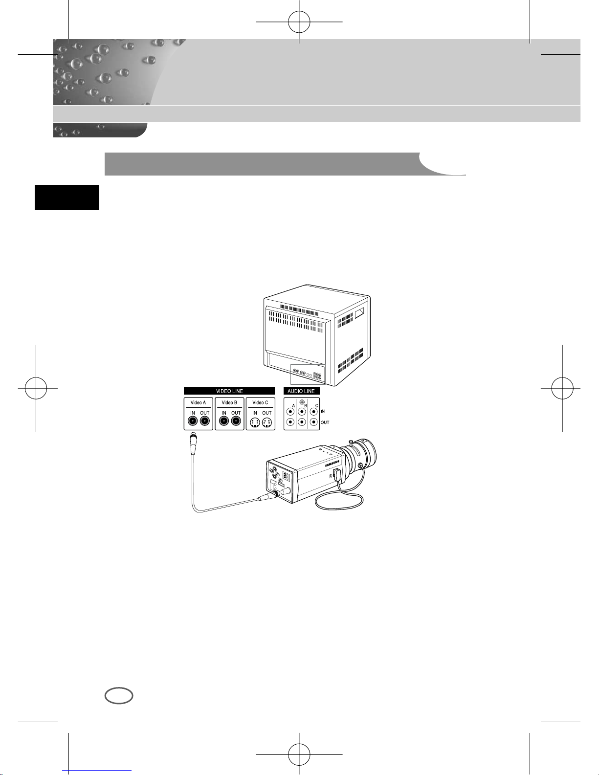
1 First, connect the connector of the BNC cable to the Video Out terminal
2 Second, connect the other connector of the BNC cable to the Video In
terminal.
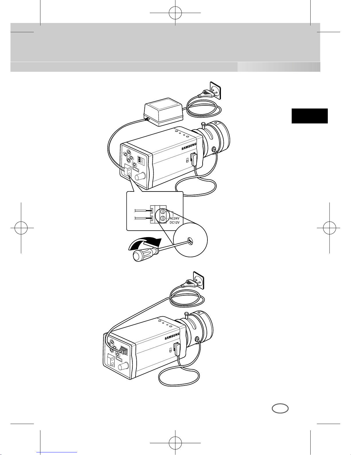
3 Then, connect the power adapter. Connect a part of the power adapter
composed of 2 lines to the Camera Power In terminal with a flat-head
driver as follows.(GND : marked with a white line)
* Power source may be AC24V or DC12V irrespective of polarity
BNC cable
Video Out Terminal
Video In Terminal of
Monitor Rear Surface
00424A SCC-B2307P-eng 4/7/05 9:12 PM ˘`18
Page 19
E
19
00424A SCC-B2307P-eng 4/7/05 9:12 PM ˘`19
Page 20
20
Chapter 5 Camera Set-Up
E
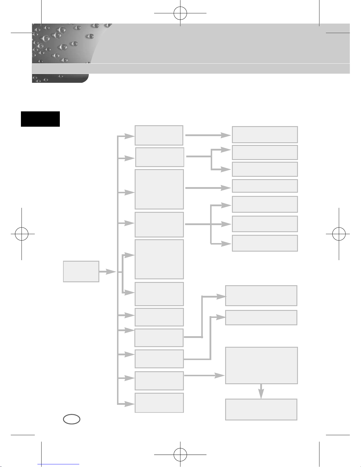
This chapter describes how to set up the camera. The first part
describes the whole set up menu and composition and the second part
describes the function of each menu.
ON...
ALC...
ELC...
BW...
EXT...
AUTO...
USER...
COLOR...
MANU...
LINE...
MOTION DET ON...
CAMERA ID
ON.../OFF
CAMERA ID AND
LOCATION SETUP
DC IRIS SETUP
LEVEL SETUP
AREA SETUP
GAIN, AGC COLOR
SETUP
BURST SETUP
BURST, LEVEL,
DURATION SETUP
3200K/5600K/USER
RED, BLUE SETUP
PHASE SETUP
AREA SETUP
SENSITIVITY SETUP
BAU DRATE D-ZOOM, PIP,
MIRROR,
POSI/NEGA,DET AIL,
MOTION DET
IRIS
ALC.../ELC...
COLOR/BW
COLOR.../BW.../
AUTO.../EXT...
SHUTTER
OFF/1/100~1/10K
OFF/AUTO X2~X128
OFF/FIX X2~X128
AGC
OFF/LOW
/HIGH
MOTION
S.SLOW~F.FAST
WHITE BAL
ATW/AWC/MANU...
SYNC
INT/LINE...
SETUP
MENU
SPECIAL
...
EXIT
QUIT/SAVE/PRESET
BLC
OFF/BOTTOM.../
TOP.../LEFT.../
RIGHT.../
CENTER.../USER..
00424A SCC-B2307P-eng 4/7/05 9:12 PM ˘`20
Page 21
E
21
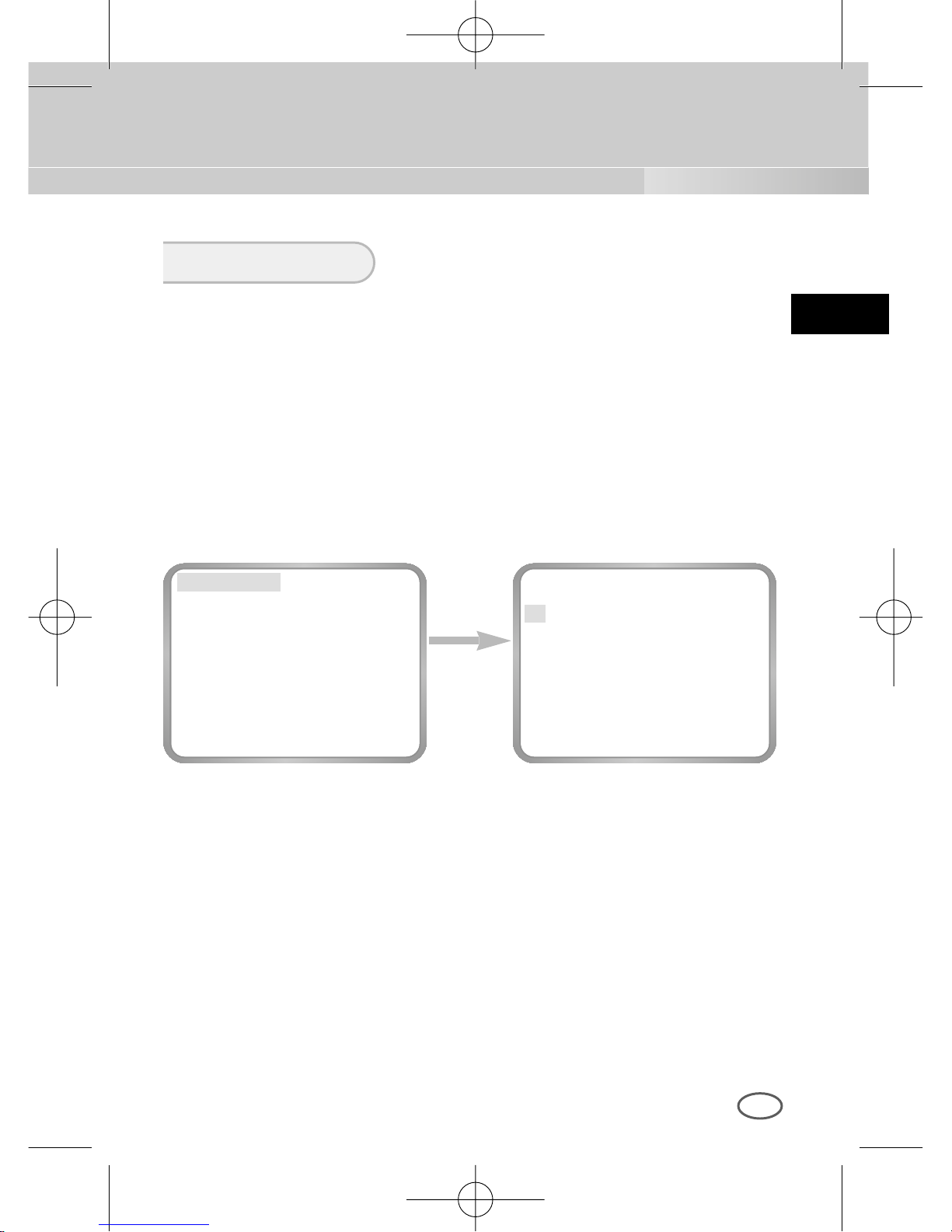
This CAMERA ID menu designates a CAMERA ID on the monitor screen
connected to the camera. If you turn on the CAMERA ID menu and press
the [ENTER] key, the sub-screen will appear to designate a CAMERA ID.
The CAMERA ID may be composed of letters, numbers, special texts, or a
combination of these up to 20 digits. The designated CAMERA ID can be
located at any place as desired by using the submenu
CAMERA ID
press the
[ENTER] key
CAMERA ID ON...
IRIS ALC...
BLC OFF
COLOR/BW COLOR...
SHUTTER AUTO X8
MOTION F.FAST
WHITE BAL ATW
SYNC INT
SPECIAL ...
EXIT QUIT
(CAMERA ID)
A B C D E F G H I J K L
M N O P Q R S T U V W
X Y Z 0 1 2 3 4 5 6 7 8 9
: ! - + * ( ) /
SP
❿❿➛➛
SP
LOCATION...
RET
....................
00424A SCC-B2307P-eng 4/7/05 9:12 PM ˘`21
Page 22
E
22
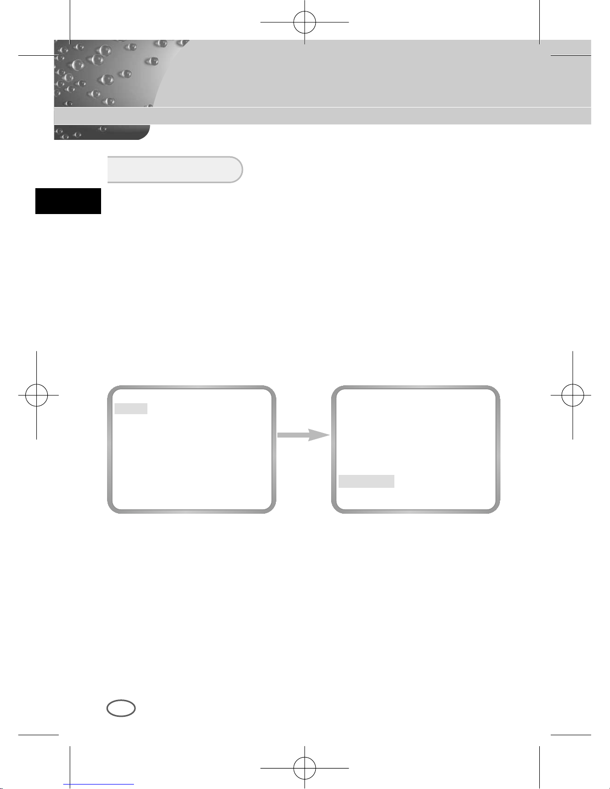
This CAMERA has an IRIS function for automatic control of the brightness
level through the intensity of radiation.
❿ ALC
If you select the ALC menu and press the [ENTER] key, the sub-screen
will appear to set the brightness level. Here, you are able to set the
brightness level by pressing the LEFT or RIGHT key in the LEVEL
menu. Level setting is available only by using the DC IRIS lens.
IRIS
press the
[ENTER] key
CAMERA ID ON...
IRIS ALC...
BLC OFF
COLOR/BW COLOR...
SHUTTER AUTO X8
MOTION F.FAST
WHITE BAL ATW
SYNC INT
SPECIAL ...
EXIT QUIT
(ALC)
DC IRIS (00) ----I---RET
00424A SCC-B2307P-eng 4/7/05 9:12 PM ˘`22
Page 23
E
23
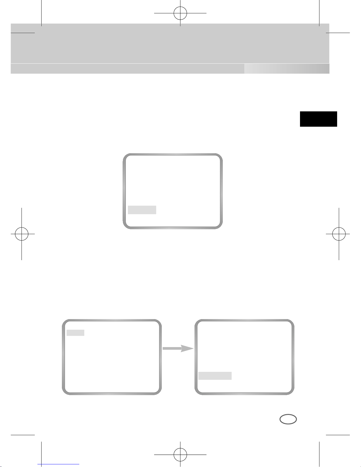
The DC IRIS level setting is available in the SETUP MENU mode as well
as in the operation mode. If you press the LEFT or RIGHT key for about
2 seconds, the DC IRIS Brightness Level setting menu will appear.
Please press the LEFT or RIGHT key to change the mode from EXIT to
SAVE and hit the [ENTER] key to save the file.
❿ ELC
This menu controls the High Speed Shutter Level within a limited range
in the event of too intensive radiation from outside while using the
Manual Lens. If you select the ELC in the IRIS menu and press the
[ENTER] key, the following subscreen will appear. Here, you are able to
set the level by pressing the LEFT or RIGHT key.
press the
[ENTER] key
CAMERA ID ON...
IRIS ELC...
BLC OFF
COLOR/BW COLOR...
SHUTTER AUTO X8
MOTION F.FAST
WHITE BAL ATW
SYNC INT
SPECIAL ...
EXIT QUIT
(ELC)
LEVEL (00) ----I---RET
DC IRIS (00) ----I---EXIT QUIT
00424A SCC-B2307P-eng 4/7/05 9:12 PM ˘`23
Page 24
E
24
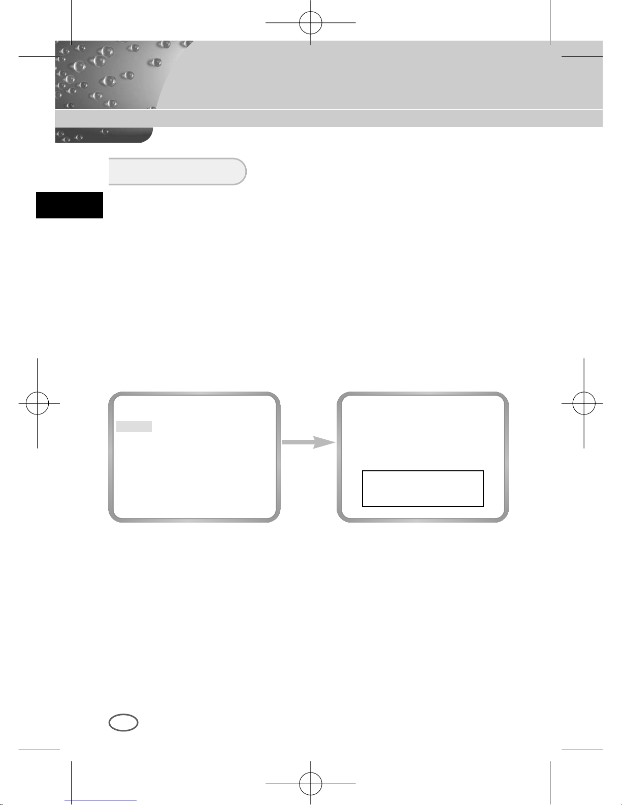
If you use an ordinary camera when there is an intense and concentrated
illumination behind an object, the back light will shade the image on the
monitor screen. The BLC function prevents such a back light effect to secure
a clear image under all illumination environments. Press the LEFT or RIGHT
key at OFF to set the USER function for a setting of the already set 5 areas
including BOTTOM..., TOP..., LEFT..., RIGHT..., and CENTER...or USER... for
a direct area setting. If you select the BOTTOM... in the BLC menu and press
the [ENTER] key, you will be able to certify the already set BOTTOM area.
BLC
press the
[ENTER] key
CAMERA ID OFF
IRIS ALC...
BLC
BOTTOM...
COLOR/BW COLOR...
SHUTTER AUTO X8
MOTION F.FAST
WHITE BAL ATW
SYNC INT
SPECIAL ...
EXIT QUIT
00424A SCC-B2307P-eng 4/7/05 9:12 PM ˘`24
Page 25
E
press the
[ENTER] key
press the
[ENTER] key
CAMERA ID OFF
IRIS ALC...
BLC USER...
COLOR/BW COLOR...
SHUTTER AUTO X8
MOTION F.FAST
WHITE BAL ATW
SYNC INT
SPECIAL ...
EXIT QUIT
25
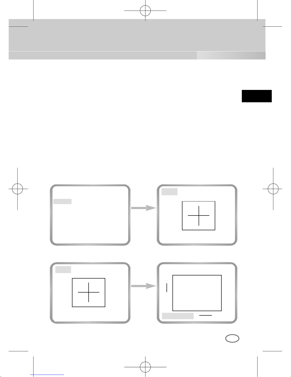
❿ USER AREA
If you select USER... in the BLC menu by using the LEFT or RIGHT key
and press the [ENTER] key, you will be able to determine the size and
location of the BLC area by yourself. When the area is not flashing, you
can specify the area size by pressing the direction keys [LEFT, RIGHT,
UP, or DOWN]. If you press the [ENTER] key when the area is not
flashing, the area will start flashing. Then you can specify the area size
by pressing the direction keys [LEFT, RIGHT, UP, or DOWN]. If you
press the [ENTER] key again, you will escape from the USER AREA
setting menu.
SIZE..
SIZE..
SIZE..
POSITION..
POSITION..
POSITION..
➛❿
❷
➛❿
❷
❷
➛❿
00424A SCC-B2307P-eng 4/7/05 9:12 PM ˘`25
Page 26
E
26
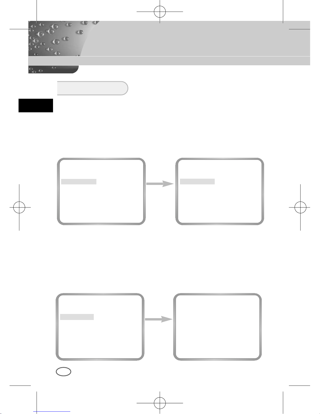
The COLOR/BW menu turns the IR(Infrared) Filter on or off. In low
illumination environments, the BW mode will turn off the IR Filter and the
sensitivity will be as high as that of BW cameras. Otherwise, the BW mode
will turn on the IR Filter and the sensitivity will return to normal to recover
the normal screen.
COLOR/BW
press the
[ENTER] key
CAMERA ID OFF
IRIS ALC...
BLC OFF
COLOR/BW COLOR...
SHUTTER AUTO X8
MOTION F.FAST
WHITE BAL ATW
SYNC INT
SPECIAL ...
EXIT QUIT
(COLOR)
GAIN (0) I-------AGC COLOR (0) ----I----
RET
Use the
[Left/Right]
Key
CAMERA ID OFF
IRIS ALC...
BLC OFF
COLOR/BW COLOR...
SHUTTER AUTO X8
MOTION F.FAST
WHITE BAL ATW
SYNC INT
SPECIAL ...
EXIT QUIT
CAMERA ID OFF
IRIS ALC...
BLC OFF
COLOR/BW BW...
SHUTTER AUTO X8
MOTION F.FAST
WHITE BAL ATW
SYNC INT
SPECIAL ...
EXIT QUIT
❿ COLOR...
This is the IR Filter ON Mode with the normal screen. If you press the
[Enter] key, you will be able to set up the COLOR GAIN LEVEL and
even the AGC COLOR LEVEL while the AGC function is activated.
00424A SCC-B2307P-eng 4/7/05 9:12 PM ˘`26
Page 27
E
27
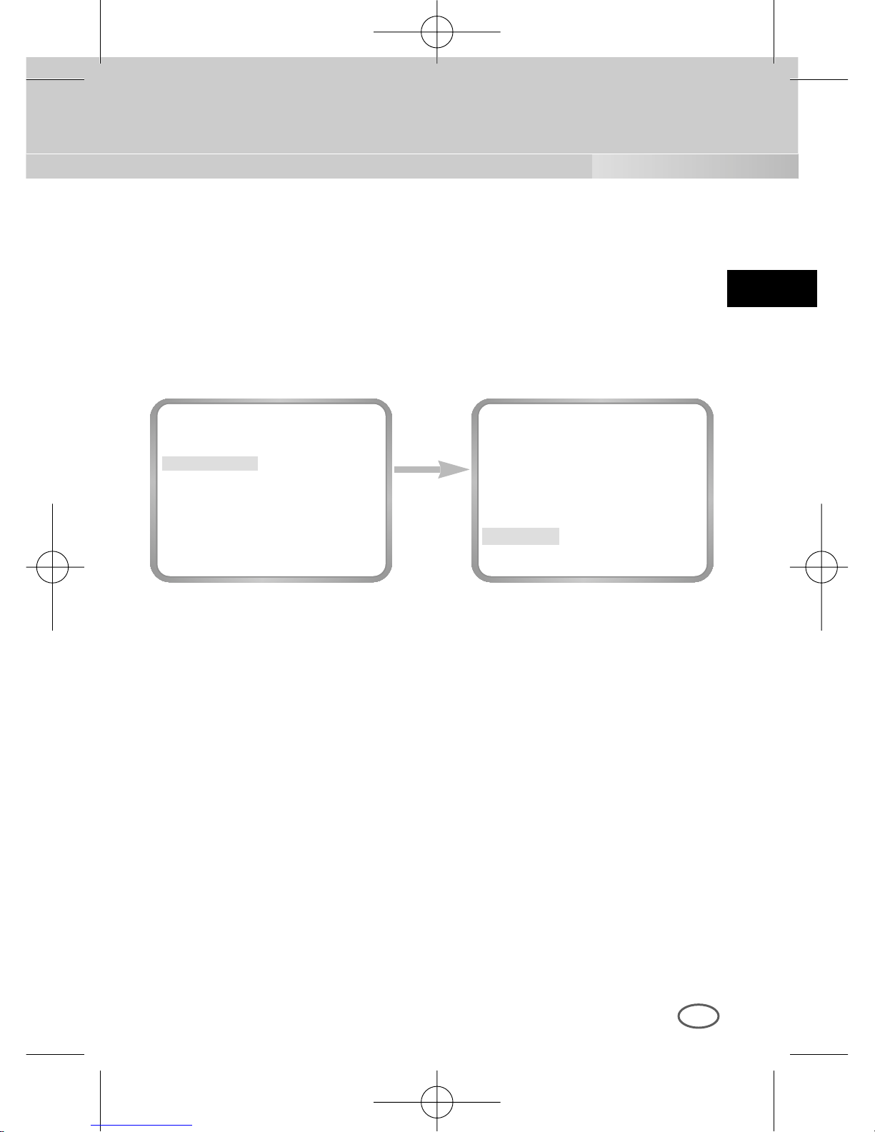
❿ BW...
This is the IR Filter OFF Mode in black and white.(high sensitivity like
BW cameras) If you select the BW... and press the [Enter] key, the BW
submenu screen will appear. You will be able to send out the BURST
signal by turning on or off in this menu.
press the
[ENTER] key
CAMERA ID OFF
IRIS ALC...
BLC OFF
COLOR/BW BW...
SHUTTER AUTO X8
MOTION F.FAST
WHITE BAL --SYNC INT
SPECIAL ...
EXIT QUIT
(BW)
BURST ON
RET
00424A SCC-B2307P-eng 4/7/05 9:12 PM ˘`27
Page 28
E
28
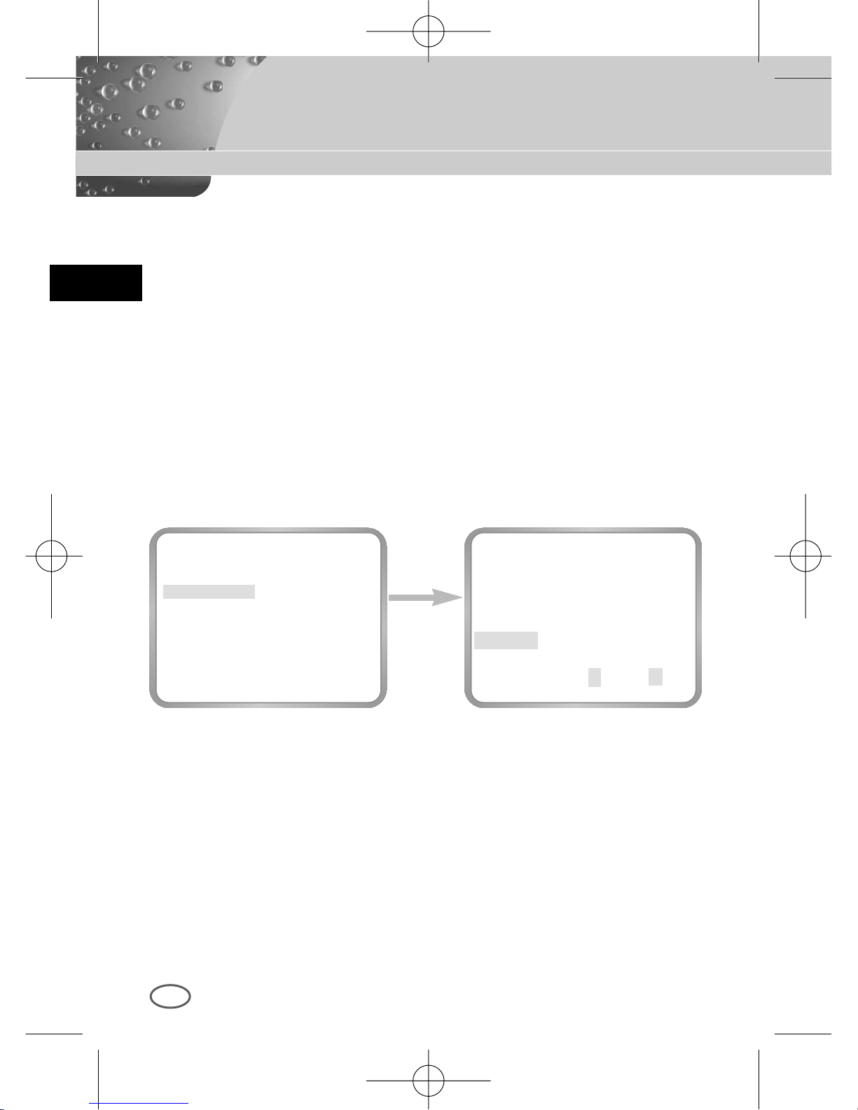
❿ AUTO...
This menu automatically converts the COLOR Mode into the BW Mode
or vice versa depending on illumination. In low illumination
environments, it turns off the IR Filter to raise sensitivity, otherwise it
turns on the IR Filter to lower sensitivity.
If you select the AUTO menu and press the [Enter] key, the BW LEVEL
Control AUTO BW submenu will appear on the menu screen. You will be
able to send out the BURST signal by turning on or off in this menu, set
up the DURATION TIME for conversion, or set up the standard
brightness level for converting the COLOR mode into the BW mode.
press the
[ENTER] key
CAMERA ID OFF
IRIS ALC...
BLC OFF
COLOR/BW AUTO...
SHUTTER AUTO X8
MOTION F.FAST
WHITE BAL ATW
SYNC INT
SPECIAL ...
EXIT QUIT
(AUTO BW)
BURST ON
DURATION (30S) -I------LEVEL L---I---H
RET
00424A SCC-B2307P-eng 4/7/05 9:12 PM ˘`28
Page 29
E
29
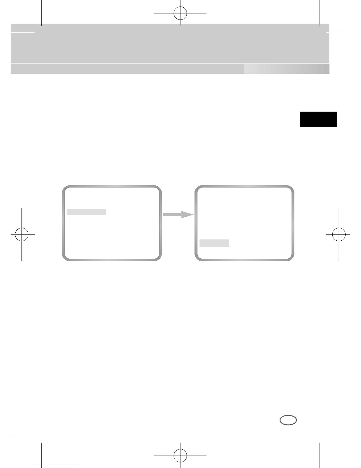
❿ EXT...
This menu automatically converts the COLOR Mode into the BW Mode
or vice versa depending on illumination with an external sensor. If you
select the EXIT menu and press the [Enter] key, the EXTERNAL BW
submenu will appear on the menu screen. You will be able to send out
the BURST signal by turning on or off in this menu.
press the
[ENTER] key
CAMERA ID OFF
IRIS ALC...
BLC OFF
COLOR/BW EXT..
SHUTTER AUTO X8
MOTION F.FAST
WHITE BAL ATW
SYNC INT
SPECIAL ...
EXIT QUIT
(EXTERNAL BW)
BURST ON
RET
00424A SCC-B2307P-eng 4/7/05 9:12 PM ˘`29
Page 30

E
30
Use
[Left/Right]
Key
CAMERA ID OFF
IRIS ALC...
BLC OFF
COLOR/BW COLOR...
SHUTTER AUTO X8
MOTION F.FAST
WHITE BAL ATW
SYNC INT
SPECIAL ...
EXIT QUIT
CAMERA ID OFF
IRIS ALC...
BLC OFF
COLOR/BW COLOR...
SHUTTER
AUTO X12
MOTION F.FAST
WHITE BAL ATW
SYNC INT
SPECIAL ...
EXIT QUIT
The SHUTTER menu sets up the high speed electronic shutter, AUTO
low speed shutter, and FIX low speed shutter. The high speed electronic
shutter covers 7 shutter speeds from 1/100 to 1/10K seconds and is
commonly used for imaging fast moving objects. Both the low speed
shutter and the FIX low speed shutter cover 12 shutter speeds from x2
to x128, which slows the shutter speed to make clearer and brighter the
screen images taken in dark illumination. If you want to slow the shutter
speed automatically depending on the degree of darkness by sensing
the intensity of radiation, please select the AUTO low speed, and if you
want to set up the shutter speed irrespective of the screen brightness,
please set up the menu starting with FIX.
If you keep pressing the LEFT or RIGHT key, the following speeds appear
in sequence.
SHUTTER
→
OFF → 1/100(NTSC), 1/120(PAL) → 1/250 → 1/500 → 1/1000 → 1/2000
→
1/4000 → 1/10K → OFF → AUTOX2 → AUTOX4 → AUTOX6 → AUTOX8
→
AUTOX12 → AUTOX16 → AUTOX24→ AUTOX32 → AUTOX48
→
AUTOX64 → AUTOX96 → AUTOX128 → OFF → FIXX2 → FIXX4 → FIXX6
→
FIXX8 → FIXX12 → FIXX16 → FIXX24 → FIXX32 → FIXX48 → FIXX64
→
FIXX96 → FIXX128
00424A SCC-B2307P-eng 4/7/05 9:12 PM ˘`30
Page 31
E
31
Use
[Left/Right]
Key
CAMERA ID OFF
IRIS ALC...
BLC OFF
COLOR/BW COLOR...
SHUTTER OFF
AGC OFF
WHITE BAL ATW
SYNC INT
SPECIAL ...
EXIT QUIT
CAMERA ID OFF
IRIS ALC...
BLC OFF
COLOR/BW COLOR...
SHUTTER OFF
AGC LOW
WHITE BAL ATW
SYNC INT
SPECIAL ...
EXIT QUIT
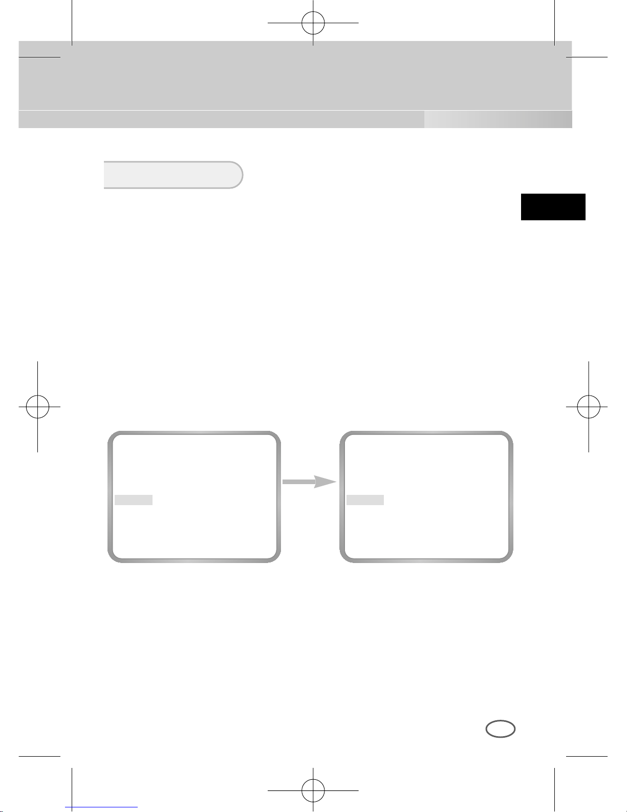
❿ AGC
The AGC menu lightens the screen below the standard brightness
because of the object taken in dark illumination. Setting up the AGC
menu is available only in either High Speed Shutter mode or OFF mode.
If you press the LEFT or RIGHT key to reach the LOW or HIGH position,
the AGC function will start activating. LOW is used for the lower AGC
GAIN whereas HIGH is used for the higher AGC GAIN.
While the COLOR/BW menu is set to AUTO, the AGC menu is all --- and
the maximum AGC GAUN stays at HIGH.
AGC/MOTION
00424A SCC-B2307P-eng 4/7/05 9:12 PM ˘`31
Page 32
E
32
Use
[Left/Right]
Key
CAMERA ID OFF
IRIS ALC...
BLC OFF
COLOR/BW COLOR...
SHUTTER AUTO X8
MOTION NORM
WHITE BAL ATW
SYNC INT
SPECIAL ...
EXIT QUIT
CAMERA ID OFF
IRIS ALC...
BLC OFF
COLOR/BW COLOR...
SHUTTER AUTO X8
MOTION FAST
WHITE BAL ATW
SYNC INT
SPECIAL ...
EXIT QUIT
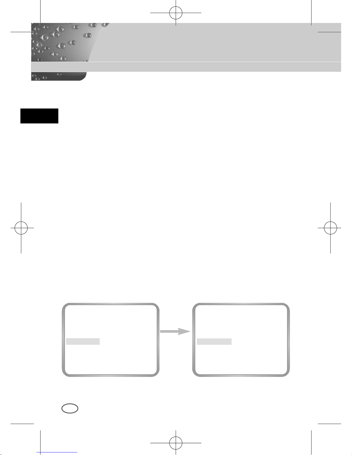
❿ MOTION
The MOTION function is available only in the AUTO or FIX mode with
these 5 steps: S.SLOW, SLOW, NORM, FAST, F.FAST.
The S.SLOW minimizes the intensity of the AGC to monitor stable
objects in the dark
The SLOW keeps the intensity of AGC low to monitor objects with a
little movement in the dark.
The NORM standardizes the intensity of AGC to monitor moving
objects in the dark.
The FAST keeps the intensity of AGC high to monitor fast moving
objects in the dark.
The F.FAST maximize the intensity of AGC to monitor very fast
moving objects in the dark.
To activate the MOTION function, you should press the DOWN key to
move the cursor to the MOTION menu and press the LEFT or RIGHT
key while the SHUTTER menu is set to either AUTO or FIX. Pressing the
LEFT and RIGHT key enables you to move to the SLOW mode and
FAST mode respectively
00424A SCC-B2307P-eng 4/7/05 9:12 PM ˘`32
Page 33
E
33
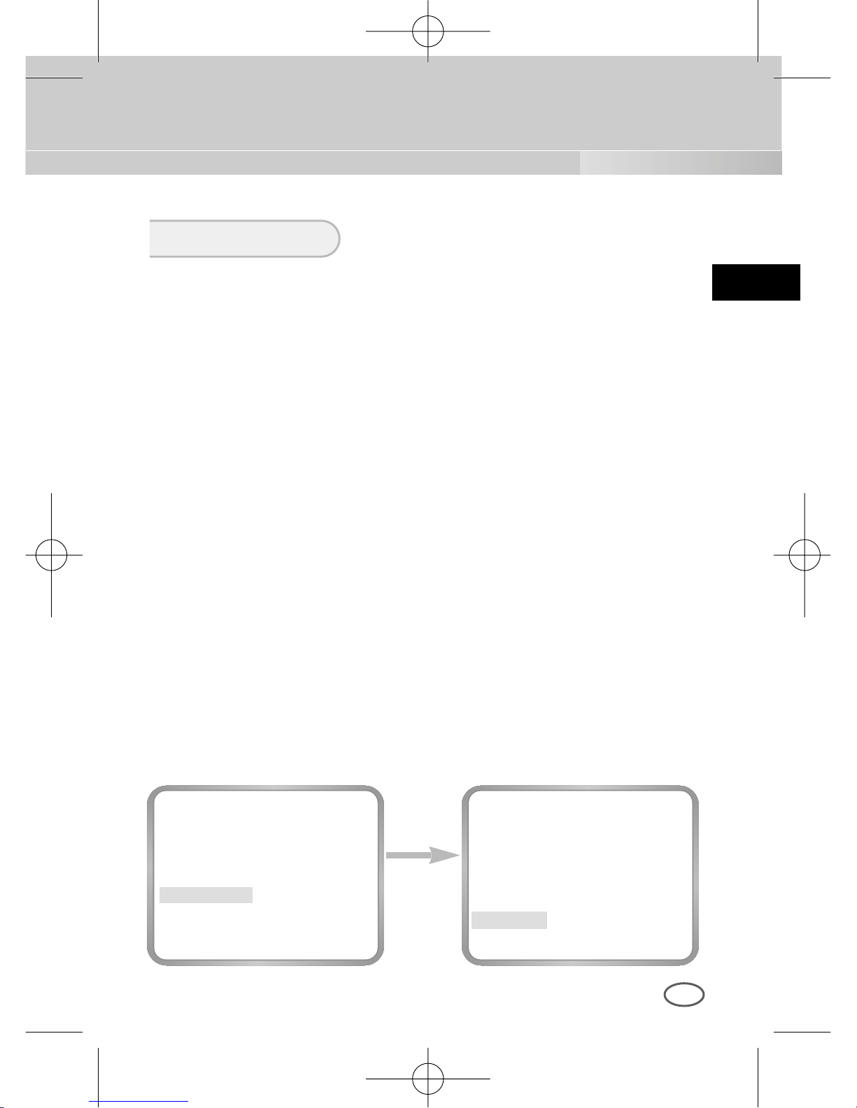
❿ ATW
If you select the ATW mode in the WHITE BAL menu, you will be able to
monitor the color temperature change by real time and set up the White
Balance to the real time color temperature automatically.
❿ AWC
If you select the AWC mode in the WHITE BAL menu, you will be able to
set up the White Balance to the real time color temperature only once
which will be maintained thereafter. If you select the AWC mode in the
WHITE BAL menu, fix a screen that you want to image, and press the
[ENTER] key. Then the AWC function will start activating.
❿ MANU...
If you select the MANU.. mode in the WHITE BAL menu, you will be able
to set up the White Balance in consideration of the current illumination
manually. If you select the MANU... item and press the [ENTER] key, the
MANU... submenu will appear to select the White Balance. If you press
the LEFT or RIGHT key in the PRESET menu, you will be able to select
the 3200K, 5600K, or USER mode.
3200K : Set the color temperature to 3200°K
5600K : Set the color temperature to 5600°K.
USER : Use the RED and BLUE control bar to select a proper value
for setup.
WHITE BAL
press the
[ENTER] key
CAMERA ID OFF
IRIS ALC...
BLC OFF
COLOR/BW COLOR...
SHUTTER AUTO X8
MOTION F.FAST
WHITE BAL MANU...
SYNC INT
SPECIAL ...
EXIT QUIT
(AWB/MANU)
PRESET 3200K
RET
00424A SCC-B2307P-eng 4/7/05 9:12 PM ˘`33
Page 34
E
34
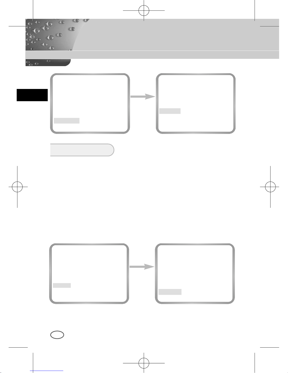
The INT mode is necessary for using the internal synchronization and
the LINE... mode is necessary for the operation of multi cameras
because it synchronizes the camera phase by using the external
signal(AC Signal). A little phase deviation for some sets may be aligned
by adjusting the PHASE. The SYNC function is available only with AC
power source. Put the cursor on the LINE..., press the LEFT/RIGHT key
to select the LINE... item, and press the [ENTER] key. Now, you will see
the submenu to adjust the PHASE. The PHASE ranges from -106H to
+106H(NTSC), -138H to +138H(PAL).
When you use DC power source, the SYNC Menu is full --- and you can
not use the SYNC function.
SYNC
press the
[ENTER] key
CAMERA ID OFF
IRIS ALC...
BLC OFF
COLOR/BW COLOR...
SHUTTER AUTO X8
MOTION F.FAST
WHITE BAL ATW
SYNC LINE...
SPECIAL ...
EXIT QUIT
(LINE LOCK)
PHASE (000) ----I---RET
press the
[Left/Right]
key
(AWB/MANU)
PRESET 3200K
RET
(AWB/MANU)
BURST OFF(USER)-RED (00) ----I---BLUE (00) ----I---RET
00424A SCC-B2307P-eng 4/7/05 9:12 PM ˘`34
Page 35
E
35
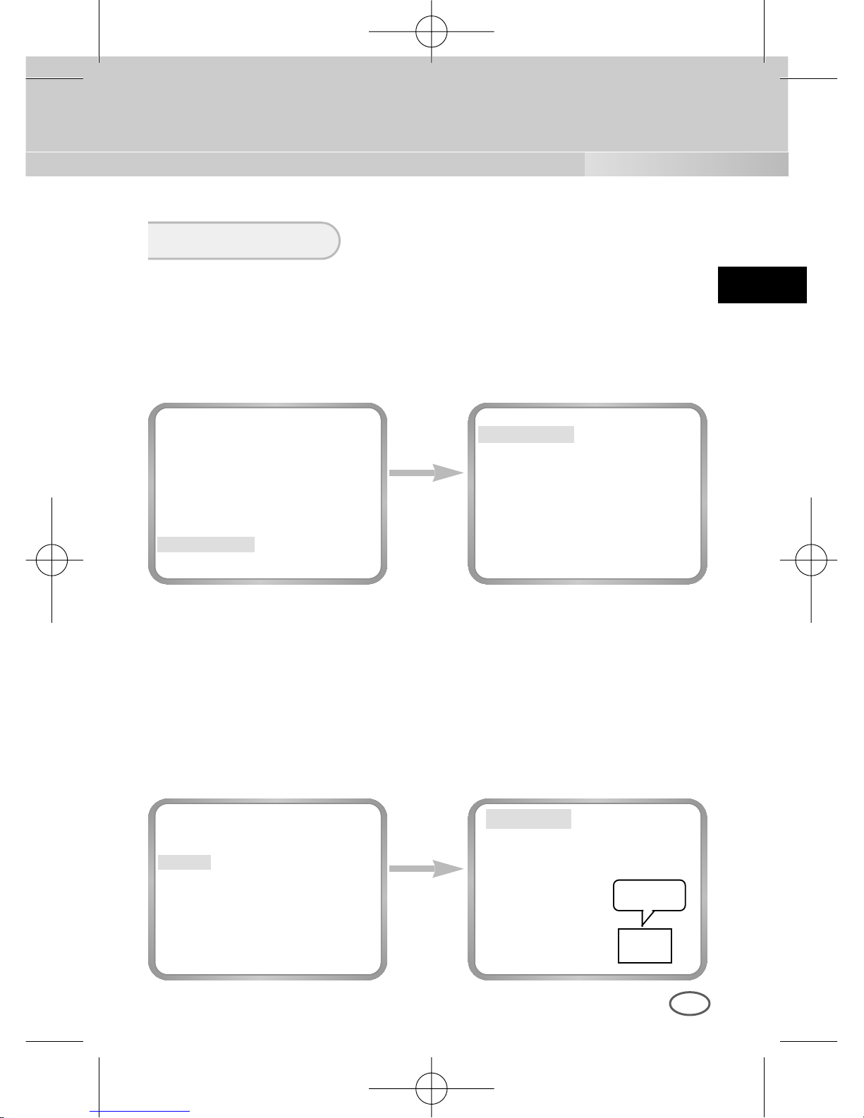
You can control the BAUD RATE, D-ZOOM, PIP, MIRROR, POSI/NEGA,
DETAIL, and MOTION DET function by yourself in the SPECIAL menu. If
your select the SPECIAL menu and press the [ENTER] key, the SPECIAL
submenu screen will appear.
SPECIAL
press the
[ENTER] key
CAMERA ID OFF
IRIS ALC...
BLC OFF
COLOR/BW COLOR...
SHUTTER AUTO X8
MOTION F.FAST
WHITE BAL ATW
SYNC INT
SPECIAL ...
EXIT QUIT
(SPECIAL)
BAUD RATE 38400
D-ZOOM OFF
PIP --MIRROR OFF
POSI/NEGA +
DETAIL (0)---+-MOTION DET OFF
LANGUAGE ENGLISH
RET
press the
[ENTER] key
(SPECIAL)
BAUD RATE 38400
D-ZOOM X2
PIP ON...
MIRROR OFF
POSI/NEGA +
DETAIL ( 0)----I-MOTION DET OFF
LANGUAGE ENGLISH
RET
❿BAUD RATE : Sets the communication speed to 4800, 9600, 19200, or
38400bps for RS-232 communication.
❿ D-ZOOM : Sets the magnification of the Digital Zoom to the 5 steps, x2,
x4, x6, x8, and x10.
❿ PIP : Picture In Picture function to show a 1/16 screen available only
with the operation of the Digital Zoom. Press the UP, DOWN, LEFT,
or RIGHT key to set up the PIP screen position.
PIP Screen
POSITION..
00424A SCC-B2307P-eng 4/7/05 9:12 PM ˘`35
Page 36
E
36
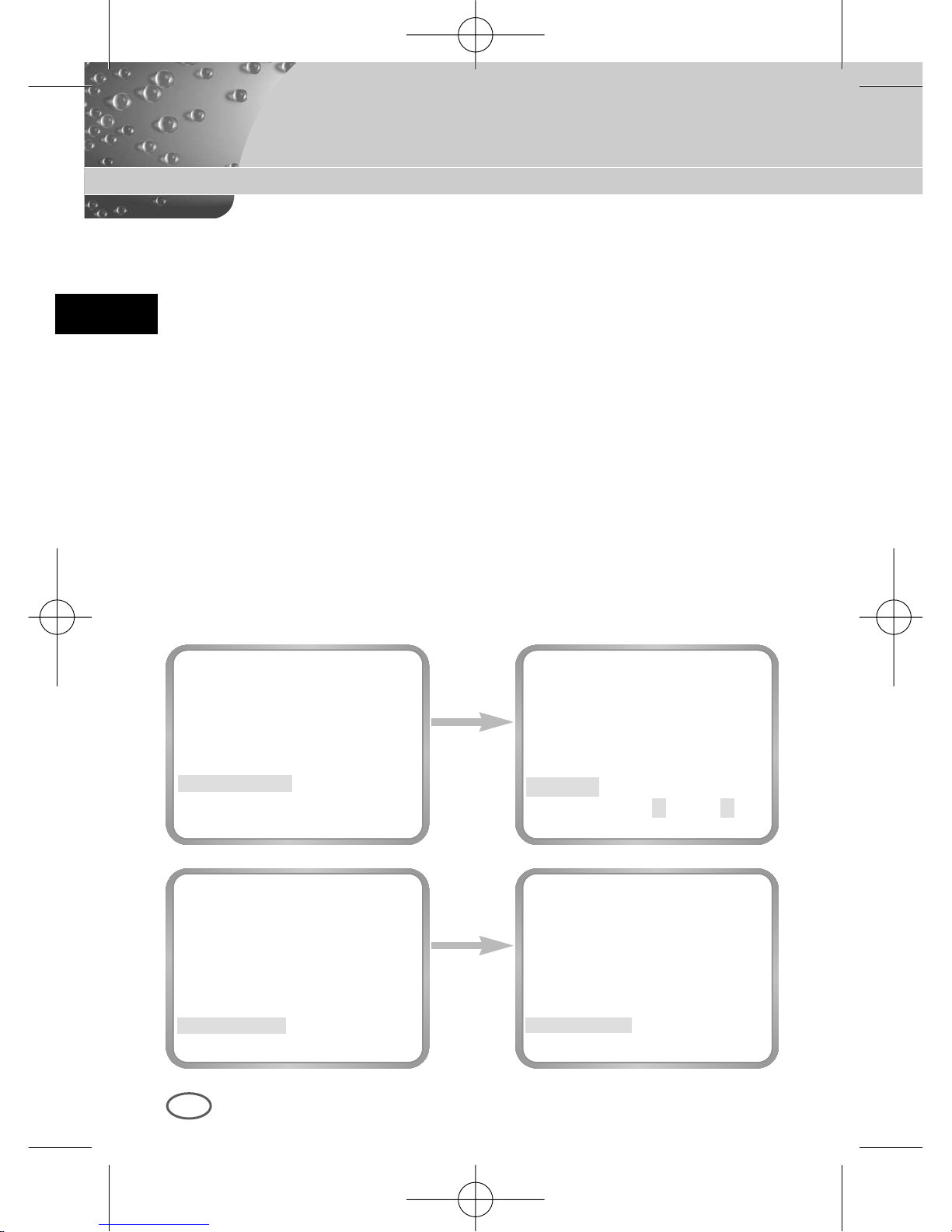
❿ MIRROR : Horizontally flips the video signal.
❿ POSI/NEGA : Outputs the video brightness signal normally or reversely.
❿ DETAIL : Adjusts the horizontal and vertical sharpness.
❿MOTION DET
MOTION DET detects any movement of objects. if you activate the
MOTION DET function at the time when you expect nobody to move, the
function will detect the movement of an intruder Once detected, the
function outputs the ALARM signal. The MOTION DET function detects
any movement and selects the movement sensitivity and the area to
detect the movement. If you select the ON... mode and press the
[ENTER] key, the MOTION DET submenu screen will appear.
❿LANGUAGE : You can choose one of the following languages: English,
German, French, Spanish, and Italian.
Use the
[Left/Right]
Key
(SPECIAL)
BAUD RATE 38400
D-ZOOM OFF
PIP --MIRROR OFF
POSI/NEGA +
DETAIL (0)---I-MOTION DET OFF
LANGUAGE ENGLISH
RET
(SPECIAL)
BAUD RATE 38400
D-ZOOM AUS
BIB --SPIEGEL AUS
POSI/NEGA +
DETAIL ( 0)----I-AKTIVITAET AUS
SPRACHE DEUTSCH
RET
Press
[ENTERt]
Key
(SPECIAL)
BAUD RATE 38400
D-ZOOM OFF
PIP --MIRROR OFF
POSI/NEGA +
DETAIL (0)---I-MOTION DET ON...
LANGUAGE ENGLISH
RET
(MOTION DET)
AREA USER...
SENSITIVITY L---I---H
RET
00424A SCC-B2307P-eng 4/7/05 9:12 PM ˘`36
Page 37
E
37
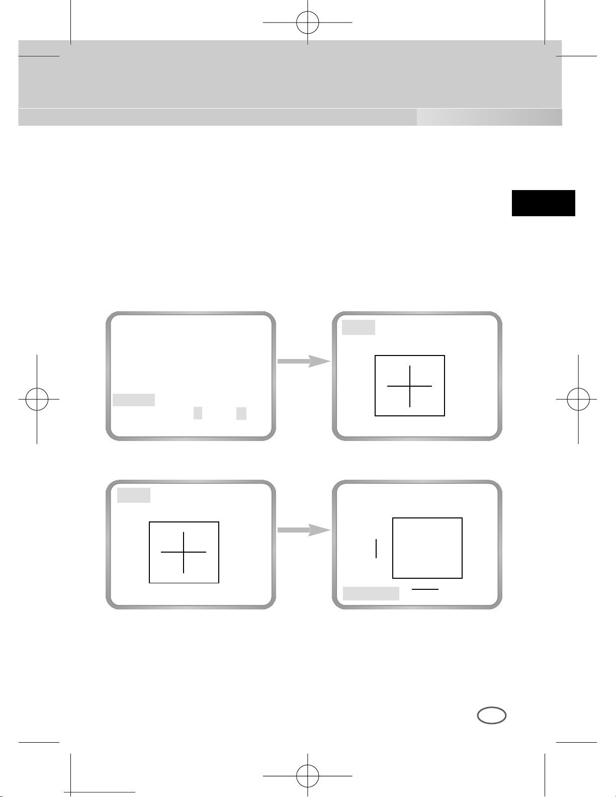
The AREA menu sets size and position like AREA in the BLC menu. If you
want to select the screen area where the MOTION DET function is applied,
you should press the [ENTER] key in the AREA USER.. by yourself or set
the AREA menu to the PRESET.. Then, the MOTION DET function will be
applied to the selected area of the product during shipment. You can also
move the cursor to the SENSITIVITY menu and press the LEFT or RIGHT
key to set up the detectability of the selected area movement.
Use the
[ENTER] key
press the
[ENTER] key
(MOTION DET)
AREA USER...
SENSITIVITY L---I---H
RET
➛❿
❷
➛❿
❷
SIZE..
SIZE
POSITION..
POSITION..
POSITION..
SIZE..
❷
➛❿
00424A SCC-B2307P-eng 4/7/05 9:12 PM ˘`37
Page 38
E
38
Use the
[Left/Right]
Key
CAMERA ID OFF
IRIS ALC...
BLC OFF
COLOR/BW COLOR...
SHUTTER AUTO X8
MOTION F.FAST
WHITE BAL ATW
SYNC INT
SPECIAL ...
EXIT QUIT
CAMERA ID OFF
IRIS ALC...
BLC OFF
COLOR/BW COLOR...
SHUTTER AUTO X8
MOTION F.FAST
WHITE BAL ATW
SYNC INT
SPECIAL ...
EXIT SAVE
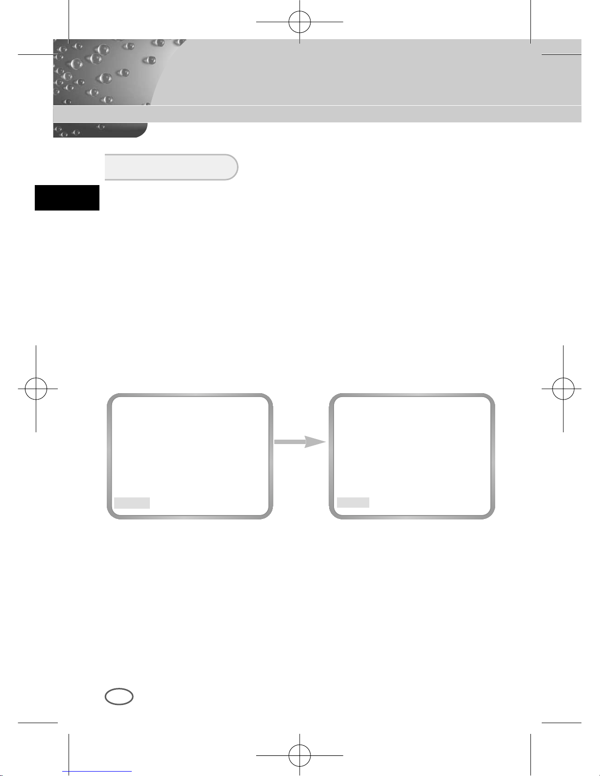
The EXIT menu is used for the termination of the CAMERA SETUP menu.
❿ QUIT
Ignores any change and returns to the previously saved SETUP menu.
❿ SAVE
Saves all the changes to the menu until now.
❿ PRESET
Ignores any change and returns to the initial value of the CAMERA
SETUP menu which was set for the product shipment.
EXIT
00424A SCC-B2307P-eng 4/7/05 9:12 PM ˘`38
Page 39
E
39
ITEM DESCRIPTION
Definition CCTV Camera (DAYNIGHT)
Power Source AC 24V ± 10% (NTSC:60Hz ± 0.1Hz),
DC12V +10% ~ -5%
Power Consumption Approx. 4.5W
Broadcasting System NTSC Standard Color System
Imaging Device 1/3 inch IT CCD
Effective Pixel
768(H) X 494(V)
Scanning Method 525 Line, 2:1 Interlace
Line Frequency Horizontal : 15,734 Hz(INT) / 15,750 Hz(L/L)
Vertical : 59.94 Hz(INT) / 60 Hz(L/L)
Synchronization Method INT/Line Lock
Resolution 500/530 TV Lines (COLOR/BW)
S/N Ratio 52dB (AGC OFF)
Minimum Scene Illumination COLOR :
0.3 Lux (F1.2) (0.002 Lux)
B/W :
0.06 Lux (F1.2) (0.0004 Lux)
Day/Night COLOR/BW/AUTO/EXT
Color Temperature ATW/AWC/MANUAL MODE
(3200°K,5600°K,R/B Gain Adjustment)
Electronic Shutter Speed ALC:OFF~1/10K sec (7 steps)
ELC:Max 1/100K sec
Back Light Compensation
OFF/BOTTOM/TOP/LEFT/RIGHT/CENTER/USER
Sense Up OFF/AUTO2X~128X/FIX2X~128X
Product Specification
SCC-B2303 Special Features
00424A SCC-B2307P-eng 4/7/05 9:12 PM ˘`39
Page 40
E
40
ITEM DESCRIPTION
Digital Zoom OFF/ON(X10), PIP
Motion Detection OFF/ON (AREA/SENSITIVITY Setting)
Video Control POSI/NEGA, Mirror(Left/Right), Detailed Setting
Signal Output Composite Video Out : 1.0 Vp-p 75 ohms/BNC
AI Lens VIDEO/DC
Lens Mount CS/C (Mount Adaptor)
Operating Temperature -10°C ~ +50°C
Operating Humidity ~90%
Physical Size 68(W) x 55(H) x 128.5(D) mm
Weight SCC-B2303 : Approx. 450g
00424A SCC-B2307P-eng 4/7/05 9:12 PM ˘`40
Page 41
E
41
ITEM DESCRIPTION
Definition CCTV Camera (DAYNIGHT)
Power Source SCC-B2303P/B2307P : AC 24V ± 10%
(50Hz ± 0.1Hz), DC12V +10% ~ -5%
SCC-B2003P/B2007P : AC220V ~ AC240V
(50Hz ± 0.1Hz)
Power Consumption SCC-B2303P/B2307P : Approx. 4.5W ,
SCC-B2003P/B2007P : Approx. 5W
Broadcasting System PAL Standard Color System
Imaging Device SCC-B2303P/B2003P:1/3 inch Super HAD CCD
SCC-B2307P/B2007P:1/3 inch EXview HAD CCD
Effective Pixel
752(H) X 582(V)
Scanning Method 625 Line, 2:1 Interlace
Line Frequency Horizontal : 15,625 Hz(INT) / 15,625 Hz(L/L)
Vertical : 50 Hz(INT) / 50 Hz(L/L)
Synchronization Method INT/Line Lock
Resolution 500/530 TV Lines (COLOR/BW)
S/N Ratio 52dB (AGC OFF)
Minimum Scene Illumination SCC-B2303P/B2003P:
COLOR :
0.3 Lux (F1.2) (0.002 Lux)
B/W :
0.06 Lux (F1.2) (0.0004 Lux)
SCC-B2307P/B2007P:
COLOR : 0.2 Lux
(F1.2) (0.001 Lux)
B/W : 0.03 Lux
(F1.2) (0.0002 Lux)
Product Specification
SCC-B2303P/B2003P/B2307P/B2007P Special Features
00424A SCC-B2307P-eng 4/7/05 9:12 PM ˘`41
Page 42
E
42
Item Description
Day/Night COLOR/B/W/AUTO/EXT
Color Temperature ATW/AWC/Manual MODE
(3200°K, 5600°K, R/B Gain Adjustment)
Electronic Shutter Speed ALC:OFF~1/10K sec (7 steps)
ELC:Max 1/100K sec
Back Light Compensation
OFF/BOTTOM/TOP/LEFT/RIGHT/CENTER/USER
Sense Up OFF/AUTO2X~128X/FIX2X~128X
Digital Zoom OFF/ON(X10), PIP
Motion Detection OFF/ON (Area/Sensitivity Setting)
Video Control Posi/Nega, Mirror(LEFT/RIGHT), Detailed Setting
Signal Output Composite Video Out : 1.0 Vp-p 75 ohms/BNC
AI Lens VIDEO/DC
Lens Mount CS/C (Mount Adaptor)
Operating Temperature -10°C ~ +50°C
Operating Humidity ~90%
Physical Size 68(W) x 55(H) x 128.5(D) mm
Weight SCC-B2303P/B2307P : Approx. 450g ,
SCC-B2003P/B2007P : Approx. 550g
00424A SCC-B2307P-eng 4/7/05 9:12 PM ˘`42
Page 43
D
TAG/NACHT FARBE KAMERA
SCC-B2303(P)/B2003P
SCC-B2307P/B2007P
BEDIENUNGSANLEITUNG
00424A SCC-B2307P-GER 4/7/05 9:44 PM ˘`1
Page 44
D
2
Sicherheitshinweise
Ziel dieser Informationen ist es, den ordnungsgemäßen Gebrauch dieses Geräts
sicherzustellen und dadurch Gefahren oder Sachbeschädigungen zu vermeiden.
Bitte befolgen Sie alle Anweisungen.
Warnung
Die Nichtbeachtung eines Warnhinweises kann zum Tode oder
zu schweren Verletzungen führen.
1. Achten Sie darauf, dass Sie nur den mitgelieferten Adapter verwenden. (Die
Verwendung eines anderen Adapters als des mitgelieferten kann Feuer, einen
Stromschlag oder die Beschädigung des Geräts verursachen.)
2. Beim Anschließen der Netz- und Signalkabel müssen zuvor die externen
Anschlussbuchsen überprüft werden. Schließen Sie die Alarmsignalkabeladern an
die Alarmanschlüsse, den Netzadapter an die Netzsteckdose und den
Gleichstromadapter an den Gleichstromeingang an, und achten Sie dabei auf die
richrige Polarität. (Ein falscher Anschluss an das Stromnetz kann Feuer, einen
Stromschlag oder die Beschädigung des Geräts verursachen.)
3. Schließen Sie nicht mehrere Kameras an einen Adapter an. (Wird die Kapazität
überschritten, kann es zu einer anormalen Wärmeentwicklung oder Feuer
kommen.)
4. Stecken Sie das Netzkabel fest in die Steckdose ein. (Ein loser Anschluss kann
Feuer verursachen.)
5. Bei der Wand- oder Deckeninstallation bringen Sie die Kamera sicher und fest an.
(Fällt die Kamera herunter, kann es zur Verletzung von Personen kommen.)
6. Plazieren Sie keine leitfähigen Gegenstände (wie z. B. Schraubenzieher, Münzen
und metallene Objekte) oder mit Wasser gefüllte Behälter auf der Kamera. (Das
kann zur Verletzung von Personen durch Feuer, Stromschlag oder
herunterfallende Gegenstände führen.)
7. Die Kamera darf nicht an einem rußigen, staubigen oder feuchten Ort installiert
werden. (Andernfalls besteht die Gefahr eines Brandes oder Stromschlags.)
8. Beim Auftreten eines ungewöhnlichen Geruchs oder einer Rauchentwicklung, die
vom Gerät ausgehen, ziehen Sie unverzüglich das Netzkabel aus der Steckdose
und wenden Sie sich an Ihr Kundendienstzentrum. (Die Fortsetzung des
Gebrauchs kann in diesem Fall zu Feuer oder einem elektrischen Schlag führen.)
00424A SCC-B2307P-GER 4/7/05 9:44 PM ˘`2
Page 45
3
D
9. Sollte das Gerät nicht störungfrei funktionieren, setzen Sie sich mit Ihrem Händler
oder dem nächsten Kundendienstzentrum in Verbindung. Das Gerät darf niemals
in keiner Weise zerlegt oder modifiziert werden. (Samsung übernimmt keine
Haftung für Probleme, die durch unbefugte Abänderungen oder einen
Reparaturversuch herbeigeführt sind.)
10. Beim Reinigen darf Wasser niemals direkt auf die Geräteteile gelangen.
(Andernfalls besteht die Gefahr eines Brandes oder Stromschlags.) Die
Oberfläche kann mit einem trockenen Tuch abgewischt werden. Verwenden Sie
für das Gerät keine Reinigungsmittel oder chemischen Reiniger, da sich durch
solche Mittel die Farbe ablösen und der Oberflächenüberzug beschädigt werden
kann.
Achtung
Die Nichtbeachtung eines mit Achtung gekennzeichneten
Hinweises kann zu Verletzungen und Sachschaden führen.
1. Lassen Sie keine Gegenstände auf das Gerät fallen, und setzen Sie es keinen
starken Stößen aus. Setzen Sie die Kamera keinen starken Vibrationen oder
magnetischen Störfeldern aus.
2. Die Kamera darf nicht an Orten mit hohen Temperaturen (über 50 °C) bzw. tiefen
Temperaturen (unter -10 °C) oder hoher Luftfeuchtigkeit installiert werden.
(Andernfalls besteht die Gefahr eines Brandes oder Stromschlags.)
3. Installieren Sie das Gerät nicht in der Nähe von Wärmequellen, wie z. B. einem
Heizgerät oder Heizkörper, und an Orten, an denen es direktem Sonnenlicht
ausgesetzt ist. (Hier besteht Feuergefahr.)
4. Wenn Sie die bereits installierte Kamera an einen anderen Ort verlegen wollen,
achten Sie darauf, die Kamera auszuschalten, bevor Sie sie abnehmen oder neu
installieren.
5. Die Installation sollte an einer gut belüfteten Stelle erfolgen.
6. Ziehen Sie bei einem Gewitter den Netzstecker. (Die Nichtbeachtung kann zu
Feuer oder einer Beschädigung des Geräts führen.)
00424A SCC-B2307P-GER 4/7/05 9:44 PM ˘`3
Page 46
D
4
INHALTVERZEICHNIS
Kapitel 1 ÜBERSICHT ....................................................... 5
Kapitel 2 SPEZIALE MERKMALE .................................... 6
Kapitel 3 BEZEICHNUNG DER TEILE UND IHRE
FUNKTIONEN .................................................... 7
Kapitel 4 INSTALLA TION ................................................... 12
V orsichtmaßnahmen für die Installation und den
Gebrauch ............................................................. 13
V erbindung des Automatischen V erschluß
Objektiv Anschlußes .......................................... 14
Einstellung des Objektivs und des Auswahl
Schalters .............................................................. 15
Einstellung des Rück-brennpunktes .................. 16
Anschluß der Kabel ............................................ 18
Kapitel 5 Einstellung der Kamera ...................................... 20
Beilage Produkt Spezifikationen ...................................... 39
HINWEIS: Richten Sie die Kamera niemals direkt auf sehr helle Objekte,
wie z. B. die Sonne, da dadurch der CCD-Bildsensor beschädigt werden
kann.
00424A SCC-B2307P-GER 4/7/05 9:44 PM ˘`4
Page 47
5
Kapitel 1 Übersicht
D
Die TAG/NACHT Kamera ist eine niedrige Beleuchtung Kamera, die
auch im dunklen Bereich der Gegenstände identifiziert; die Kamera
betreibt in der Farbmode über den bestimmten Beleuchtung und
andernfalls in der SW Mode beseitigt die IR Cut Funktion.
Inzwischen, ist es eine Sense Up Funktion aufgenommen, mit Hilfe
des Langezeit Verschlußes und der Field Anhäufung Methode, um
die Leistung der niedrigen Beleuchtung Eigenschaft zu verbessern.
Die TAG/NACHT Kamera ist meistens an der dunklen Stelle, wie am
Untergeschoß-parkplatz benutzt werden. Am Tag, als Farbmode der
hohen Dichte mit einer horizontalen 480 Resolution wird es besorgt,
und an der Nacht die TAG/NACHT Funktion dazu die Sense Up
Funktion wird es nutzen, den Objekt zu identifizieren. Außerdem,
könen Sie diese Kamera zusätzlich in Bezug auf die Infrarot
Emission Geräte benutzen.
[TAG/NACHT]
Es ist eine Funktion einer Farbkamera; diese Funktion
unter bestimmten Beleuchtung beseitigt den Filter, der eine
IR Cut Funktion hat, um eine bessere Empfindlichkeit zu
haben.
00424A SCC-B2307P-GER 4/7/05 9:44 PM ˘`5
Page 48
6
Kapitel 2 Speziale Merkmale
D
Hohe Empfindlichkeit
Es hat ein neuesten 1/3" Super(EXview)-HAD IT CCD für ein Bild der
hohen Empfindlichkeit.
Niedrige Beleuchtung Funktion
Es hat beide Funktionen; eine Illumination Funktion und TAG/NACHT
funktion auf Grund der Digitalsignal Technologie, um in der schlechten
Umgebung ohne Licht betreiben zu können.
Digitel Zoom Funktion
Es hat eine Digital Zoom Funktion für eine maximun 10mal Vergrößerung.
(Wenn Sie die PIP Funktion zur Digital Zoom Mode wenden, wird das
ganze Bild zum PIP Bild aufgezeigt werden.)
Superior Gegenlicht Einstellung Funktion
Im Fall von einer hellen Beleuchtung oder Sonnenstrahlen hinter dem
Gegenstand kann das Bild, das wegen der Gegenlicht verdunkelt worden
war, deutlich aufgenommen werden.
Digital Stromquelle Synchronisation Methode
Mit dem Vollen Digital Methode Linie Schluß (Line Lock) kann man die
vertikale Synchronisation der Kamera direkt struern, so die Kontrollfähigkeit
und die Zuverläßigkeit der Kamera zu verbessern.
Resolution
Es verwirklicht eine hohe Resolution von vollen digitalen Bild-Entwickellung
mit der höchsten Digital Signal Technologie.
Ausgabe Signal Einstellung
Es ist möglich, das Video Ausgabe Signal umzukehren und eine
vertikalen/horizontalen Profil einzustellen.
00424A SCC-B2307P-GER 4/7/05 9:44 PM ˘`6
Page 49
7
Kapitel 3 Teilnamen und Funktionen
D
Seite Ansicht
Passepartout Adapter Befestigungsrille
Diese Rille benutzt für die Befestigung des Adapters, ein Teil der Klammer
wo die Kamera installiert wird.
Automatische Verschluß Objektive (Option)
Dieses Objektiv ist in der Kamera installiert werden.
* Eine Objektiv der Oberfläche der Kamera muß mit einem Objektivpapier
oder in Äthan benetzten Baumwolltuch sanft reinigen werden.
Automatischer Verschluß Objektiv Anschluß
Dieser Anschluß versorgt das automatische Verschluß Objektiv mit dem
Strom-versorgung, Kontrollsignal, Videosignal oder DC Signal, nötwendig
für die Kontrolle des Objektiv-verschlußes.
Automatische Verschluß
Objektive Kontrollkabel
ALC Objektiv
Auswahlschalter
Automatischer Verschluß
Objektiv Anschluß
Passepartout Adapter
Befestigungsrille
Gegen Brennpunkt (Back
Focus) Kontrollstab
Kamera Objektiv
00424A SCC-B2307P-GER 4/7/05 9:44 PM ˘`7
Page 50
D
8
Automatische Verschluß Objektiv Kontrollkabel
Diese Kabel senden das Kontrollsignal von der Kamera über, den Objektiv
Verschluß zu kontrollieren.
Gegen Brennpunkt (Back Focus) Kontrollstab
Es kontrolliert das Gegenbrennpunkt.
ALC Objektiv Auswahlschalter
Dieser Schalter stellt für die Verwendung des Auto Blende-blende
Verschluß Typs ein.
DC : Wenn Sie ein Auto Blende-blende Objektiv gebraucht mit dem DC
Kontrollsignal eingestellt haben, wählen Sie dieser Schalter zur DC Position.
VIDEO : Wenn Sie ein Auto Blende-blende Objektiv mit dem VIDEO
Kontrollsignal eingestellt haben, wählen Sie dieser Schalter zur VIDEO
Position.
Vista Posteriore
00424A SCC-B2307P-GER 4/7/05 9:44 PM ˘`8
Page 51
D
9
① Strom Anzeiger LED
Wenn die Kamera mit dem Strom geliefert ist, schaltet LED ein.
➁ Video Ausgabe Terminal
Der Monitor Video Input Terminal ist angeschloßen, mit diesem Terminal,
der durch diesen Terminal das Videosignal der Kamera senden.
➂ Fernbedienung Input Terminal (RS-232)
Dieser Terminal ist für die Kamera Kontrolle an der Produktion Fabrik.
1 TXD
2 RXD
3 +5V
4 GND
1
2 3 4
00424A SCC-B2307P-GER 4/7/05 9:44 PM ˘`9
Page 52
D
10
➃ TAG/NACHT Außensignal Input ? ALARM Signal Ausgabe
Diese Funktion empfängt das außen TAG/NACHT Signal von dem
Außenlicht Sensor (Option) und zum SW umwandeln lassen.
Die BEWEGUNG DET Funktion führt zu einem ALARM Signal wenn
eine Bewegung wahrgenommen wird.
①
➁
TAG/NACHT IN
GND
ALARM OUT
Ein Außensensor zum TAG/NACHT Terminal anschließen, wie Nummer ①
zeigt.
Die Äußerengeräte wie ein Summer oder eine Lampe zum ALARM Terminal
anschließen, wie Nummer ➁ zeigt.
Der ALARM Ausgabe Terminal ist ein offene Einnehmer mit dem folgenden
Fassungsvermögen ; DC 16V und 100 mA
AUS (OFF) : Offener Kontakt
EIN (ON) : Unter 100mA
Der TAG/NACHT Input Terminal hat ein Input DC 5V Pull-up, über 0.2mA.
AUS (OFF) : Offener Kontakt
EIN (ON) : Geschloßener KOntakt
00424A SCC-B2307P-GER 4/7/05 9:44 PM ˘`10
Page 53
D
11
⑤ Kamera Betriebsschalter (Setup Schalter)
Diese Funkton des Kamera Betriebsschalters ist anhängig von der
Kamera ob sie zur Zeit in der üblichen Mode (kein Setup Menu ist auf
das Bild aufgezeigt) ist, oder in der Setup Menu Mode.
In der üblichen Betriebsmode
[LINKS/RECHTS] Taste : Beide Tasten für ca. 2 Sekunden drücken
und das Menu eingeblendet, den DC BLENDE Niveau zu kontrollieren.
Die Taste [LINKS] läßt den Niveau niedrig und die Taste [RECHTS] höher.
[ENTER] Taste : Es benutzt für die Ausführung des Setup Menus. (Über 2
Sekunden drücken.)
In der Setup Menu Mode
[OBEN/UNTEN] Richtungstaste : Diese Tasten werden bei der Bewegung
des Sursors nach oben oder unten benutzt.
[LINKS/RECHTS] Richtungstaste : Diese Tasten werden bei der Bewegung
des Cursors nach LINKS oder RECHTS benutzt, und auch bei der
Zuweisung in jedem Setup Menu, der Wert Reihenweise zu
identifizieren.
[ENTER] Taste : Diese Taste wird benutzt zu dem Untermenubild gewählt
von dem Setupmenu auszuführen, oder der laufende Wert
einzustellen.
➅ Strom Anschluß Terminal
Dieses Terminal wird zum Strom (Adapter)-kabel angeschloßen.
[LINK/RECHTS] Taste
[ENTER] Taste
[OBEN/UNTEN] Taste
00424A SCC-B2307P-GER 4/7/05 9:44 PM ˘`11
Page 54
12
Kapitel 4 Installation
D
In diesem Kapitel wird erläutert, was vor der Installation der Kamera zu
beachten ist, wie man eine geeignete Installationsstelle auswählt und
welche Vorsichtsmaßnahmen bei der Installation zu treffen sind. Nun
können Sie die Kamera installieren und die Kabel anschließen.
Überprüfen Sie bitte, ob die folgende Zubehörteile im Lieferumfang
enthalten sind.
Vor der Installation
Überprüfung des Inhalts in der Verpackung
Kamera Kamera Stütze
(Passepartout)
C Passepartout
Adapter
Auto Blende Objektiv
Anschluß
Manuale
d’utenteBedienungs
anleitung
00424A SCC-B2307P-GER 4/7/05 9:44 PM ˘`12
Page 55
D
13
① Der Benutzer darf niemals selber die Kamera demontieren.
➁ Bei dem Umgehen der Kamera immer vorsichtig sein.
Die Kamera nicht mit der Faust schlagen oder schüttern.
Die Kamera muß mit Vorsicht lagert und behandelt werden, vom
Schaden zu vermeinden.
➂ Achten Sie darauf, daß die Kamera an einer regenfreien oder nicht
feuchten Lage installiert werden und an der naßen Lage nicht betreiben
lassen.
➃ Nicht schrubben die Kamera mit dem rauhen Sandpapier und beim
Reinigen benutzen Sie die Trockentücher.
⑤ Installieren Sie die Kamera an einem kühlen Ort und nicht in direkten
Sonnenlicht.
Vorsichtsmaßnahmen für die Installation und den Gebrauch
00424A SCC-B2307P-GER 4/7/05 9:44 PM ˘`13
Page 56
D
14
Verbindung des Automatischen Verschluß Objektiv Anschlußes
Der Kamera, dazu der Automatische Verschluß Objektiv Anschluß wie folgt
vorbereiten:
Jede Abgezogene Verschluß Kontrollkabel Leitung zu dem automatischen
Verschluß Objektiv Anschluß wie folgt verbinden.
Stecknadel Nr. DC Kontrolltyp VIDEO Kontrolltyp
1 Damp(-) Strom (+12V)
2 Damp(+) N/A
3 Drive(+) VIDEO Signal
4 Drive(-) GROUND
00424A SCC-B2307P-GER 4/7/05 9:44 PM ˘`14
Page 57
D
15
Installation
Einstellung des Objektivs
CS Objektive Fall
Der CS Objektiv im Uhrzeigersinn drehen, bis es wie unten befestigt
wird.
C Objektive Fall
Der C Passepartout Adapter im Uhrzeigersinn drenen, um es zu
befestigen.
Dann drehen der C Objektiv im Uhrzeigersinn, bis es wie unten befestigt
wird.
CS Objektive
C Objektive
00424A SCC-B2307P-GER 4/7/05 9:44 PM ˘`15
Page 58
D
16
Einstellung des Auswahlschalters
Einstellung des Rück-brennpunktes (Back Focus)
Sie müßen die Position des Objektiv Einstellschlter neben der Kamera, je nach
dem Objektivtyp ändern.
Sie müßen der Schalter in der "DC" oder beziehungsweise "VIDEO" Position
drehen, ob der Einstellobjektiv DC Kontrolltyp automatische Verschlußobjektiv
ist oder der Video Kontrolltyp automatische Verschluß-objektiv ist.
Die Kamera Rück-brennpunkt ist in der Fabrik vor der Lieferung eingestellt,
aber einige Objektive sind aus dem Brennpunkt, je nach der Objektivtypen.
Wenn es so ist, müßen Sie der Rück-brennpunkt wie folgt einstellen.
Zuerst, es ist das Rück-brennpunkt Einstell-verfahren für die Fixierten
Brennpunkt Objektive.
Objektive ohne Zoom Funktion
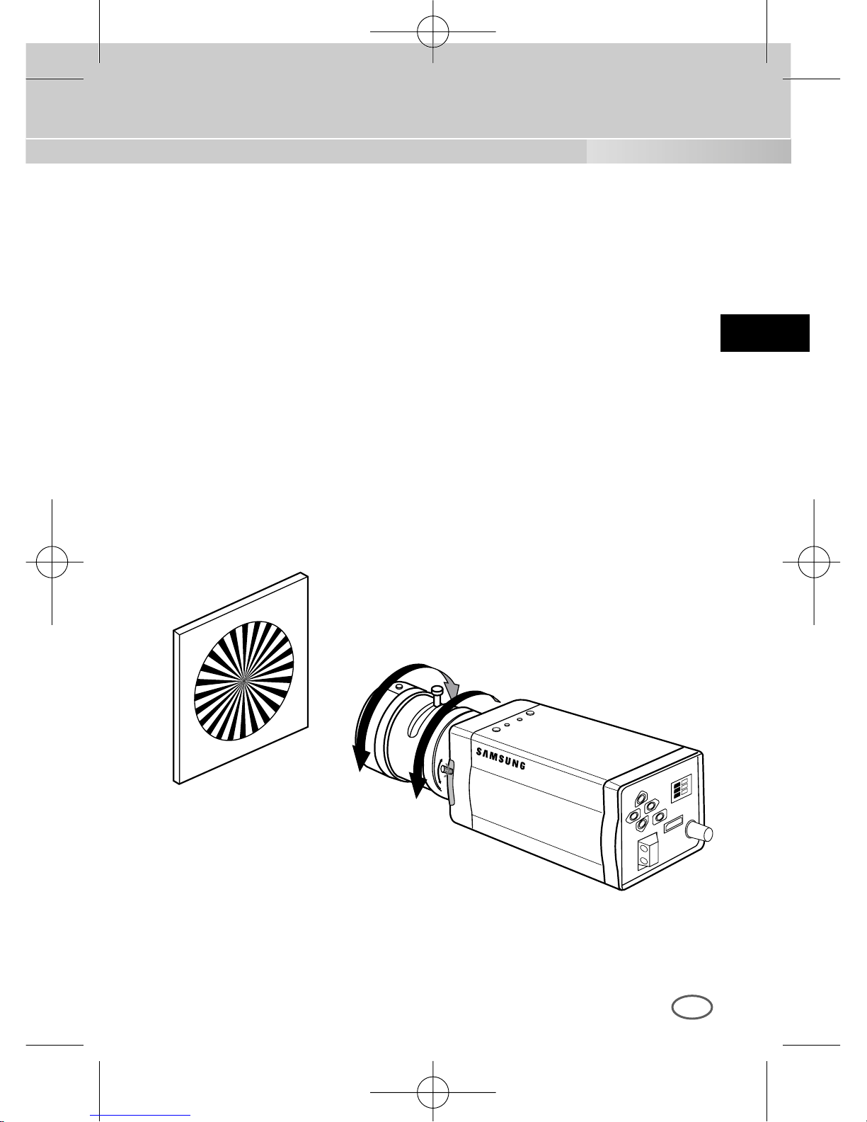
① Ein Gegenstand mit hocher Resolution (Gitterförmige Gegenstand) über
als 10m Entfernung einbilden und der Objektiv Brennpunktring in der
Unendlichkeit ( ∞ ) Position legen.
➁ Der RÜCK-BRENNPUNKT Einstellring drehen, bis der Gegenstand
deutlicher sein wird.
➂ Die Fixierschraube des RÜCK-BRENNPUNKT Einstellrings einschrauben.
00424A SCC-B2307P-GER 4/7/05 9:44 PM ˘`16
Page 59
D
17
Objektive mit Zoom Funktion
① Ein Gegenstand mit hocher Resolution (Gitterförmige Gegenstand)
einer Entfernung 3m bis 5m einbilden und der Zoom in dem Objektiv zu
TELE als möglich nahe einstellen. Dann drehen der Objektiv
Brennpunktring, bis der Gegenstand deutlicher sein wird.
➁ Der Zoom in dem Objektiv zu WIDE als möglich nahe einstellen und
dann drehen der RÜCK-BRENNPUNKT Einstellstab, bis der Gegenstand
deutlicher sein wird.
➂ Nummer ① bis ➁ und für 2 oder 3 male wiederholen, bis der Brennpunkt
auf der ZOOM TELE Seite mit denem auf der ZOOM WIDE Seite
deutlich passen wird.
00424A SCC-B2307P-GER 4/7/05 9:44 PM ˘`17
Page 60
D
18
Anschluß der Kabel und Überprüfung des Betriebs
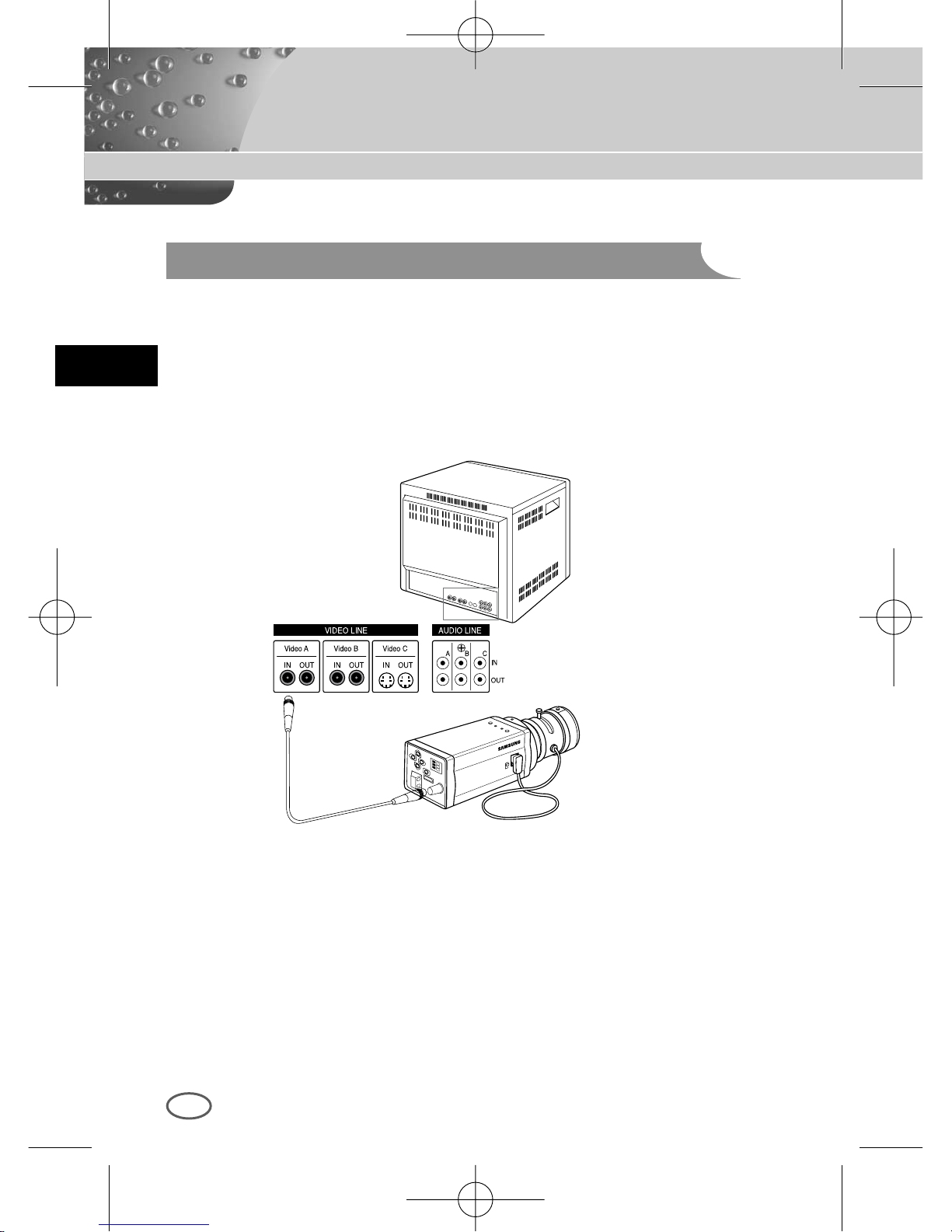
1 Schließen Sie zuerst das eine Ende des BNC-Videokabels an den
Videoausgang (VIDEO OUT) an.
2 Schließen Sie als nächstens das andere Ende des BNC-Kabels an die
Videoeingangsbuchse des Monitors an.
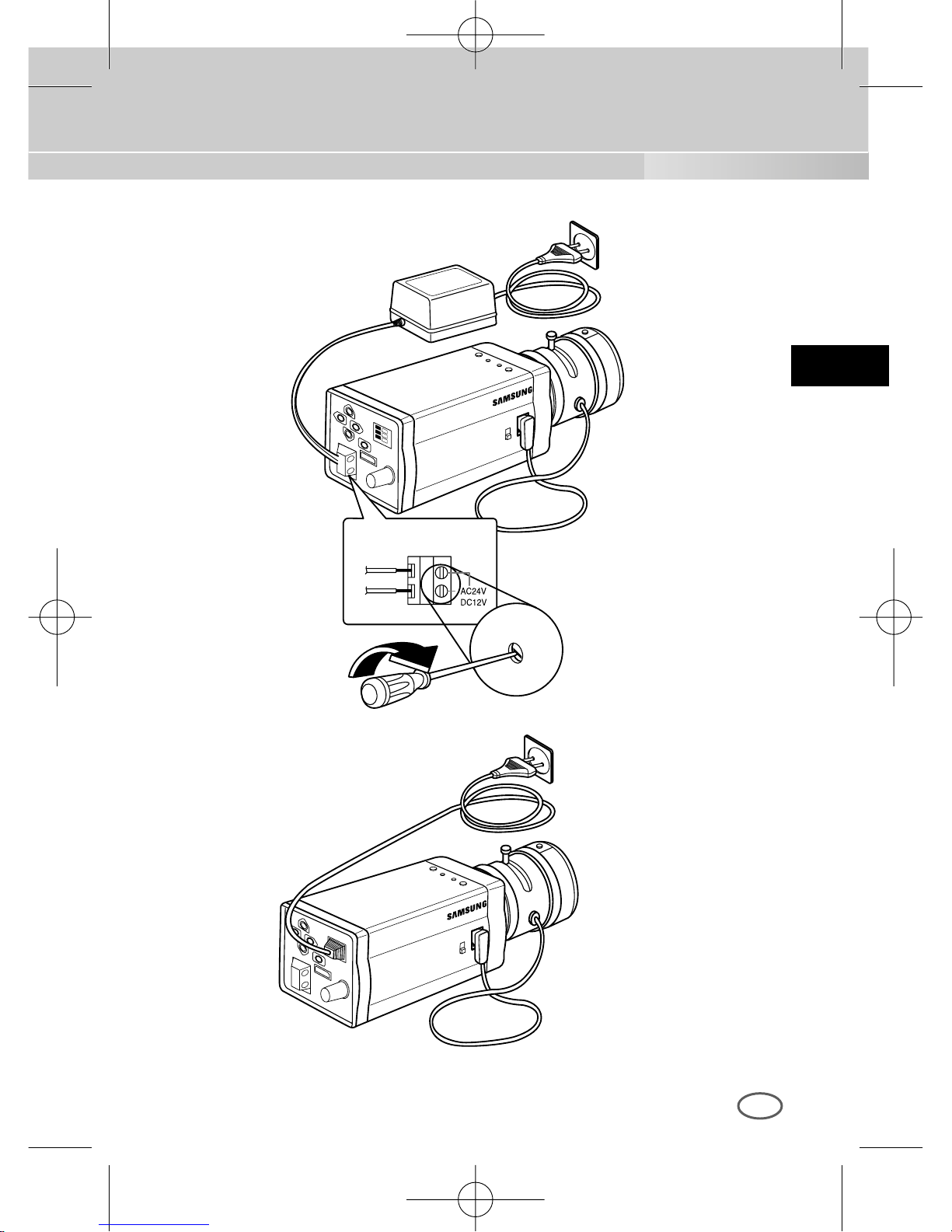
3 Schließen Sie dann Netzadapter an. Verwenden Sie einen
Schlitzschraubenzieher, um das zweiadrige Ende des Netzadapters an
den Netzeingangsanschluß der Kamera wie folgt anzuschließen. (GND:
mit einer weißen Linie auf dem Kabel gekennzeichnet.)
* Die Stromquelle kann mit AC24V und DC12V ungeachteter Polatität
anschließen.
BNC KABEL
VIDEO AUS
TERMINAL
VIDEO EIN TERMINAL
des Monitor-hinterteils
00424A SCC-B2307P-GER 4/7/05 9:44 PM ˘`18
Page 61
D
19
00424A SCC-B2307P-GER 4/7/05 9:44 PM ˘`19
Page 62
20
Kapitel 5 Aufbau der Kamera
D
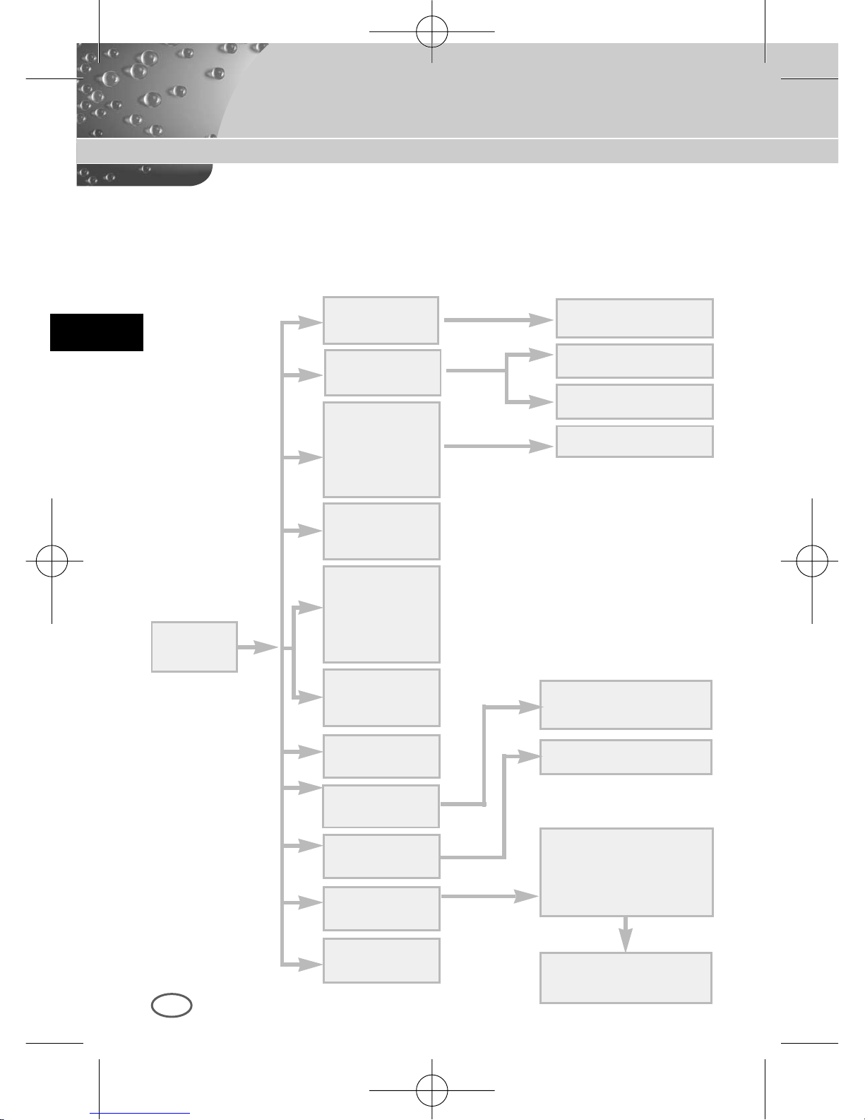
Dieses Kapatel gibt einen Überblick über den Aufbau der Einstellmenu.
Zuerst das Totale Einstellmenu und der Aufbau und dann erläutert ihre
Funktionen.
EIN...
ALC...
ELC...
BENUTZER
...
MANU...
LINE...
AKTIVIT AET EIN...
KAMERA ID
EIN.../AUS
KAMERA ID AND
LOCATION SETUP
DC BLENDE SETUP
PEGEL SETUP
BEREICH SETUP
3200K/5600K/BENUTZER
ROT, BLAU SETUP
PHASE SETUP
BEREICH SETUP
SENSITIVITY SETUP
BAUD RATE D-ZOOM, BIB,
SPIEGEL, POSI/NEGA,
DET AIL, AKTIVIT AET
BLENDE
ALC.../ELC...
FARBE/S/W
FARBE.../S/W.../
AUTO.../EXT...
SHUTTER
AUS/1/100~1/10K
AUS/AUTO X2~X128
AUS/FEST X2~X128
AGC
AUS/WENIG
/HOCH
BEWEGUNG
S.LANGS~S.SCHN
WEISSABGL
ATW/AWC/MANU...
SYNC
INT/LINIE...
SETUP
MENU
SPEZIAL
...
AUSGANG
VERL/SICHERN/PRESET
BLC
AUS/UNTEL.../
OBEN.../LINKS...
RECHTS.../MITTE.../
BENUTZER...
00424A SCC-B2307P-GER 4/7/05 9:44 PM ˘`20
Page 63
D
21
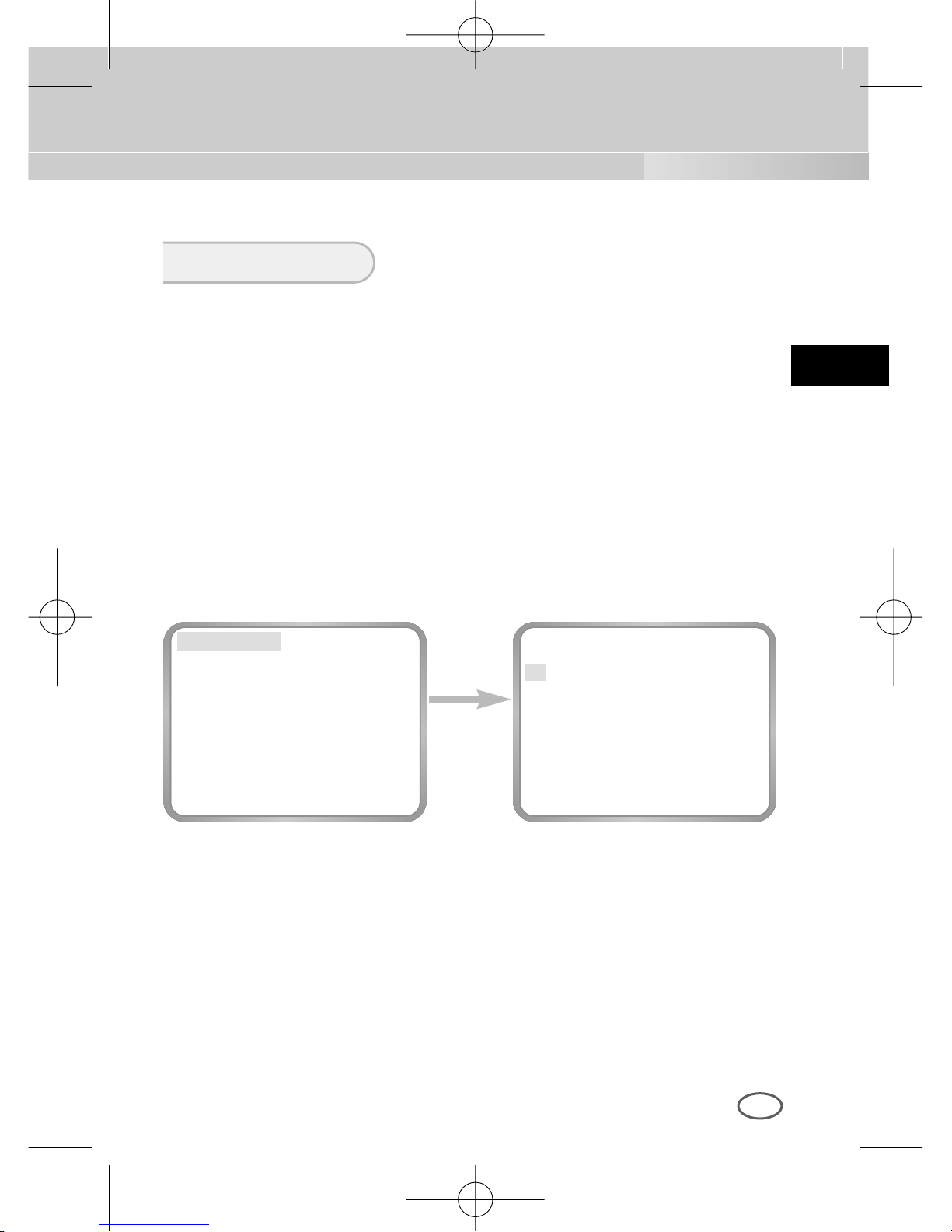
Im Menu KAMERA ID können Sie eine Kennung für die Kamera festlegen,
die auf dem Bildschirm des mit der Kamera angeschloßene Monitors
erscheint. Wenn Sie im Einstellmenu KAMERA ID auf EIN stellen und
[ENTER] drücken, wird ein Untermenubildschirm eingeblendet, in dem Sie
der Kamera eine Kennung zuweisen können.
Dazu können Sie max. 20 alphamunerische Zeichen und einige
Sonderzeichen verwenden, die in KAMERA ID gezeigt werden.
Der gezeigte KAMERA ID können Sie im Untermenu POSITION an einer
bestimmten Stelle auf dem Monitor plazieren.
KAMERA ID
Die Taste
[ENTER]
drücken
KAMERA ID AUS
BLENDE ALC...
BLC AUS
FARBE/S/W FARBE...
SHUTTER AUTO X8
BEWEGUNG S.SCHN
WEISSABGL ATW
SYNC INT
SPEZIAL ...
AUSGANG VERL
(KAMERA ID)
A B C D E F G H I J K L
M N O P Q R S T U V W
X Y Z 0 1 2 3 4 5 6 7 8 9
: ! - + * ( ) /
SP
❿❿➛➛
SP
POSITION...
RUE
....................
00424A SCC-B2307P-GER 4/7/05 9:44 PM ˘`21
Page 64
D
22
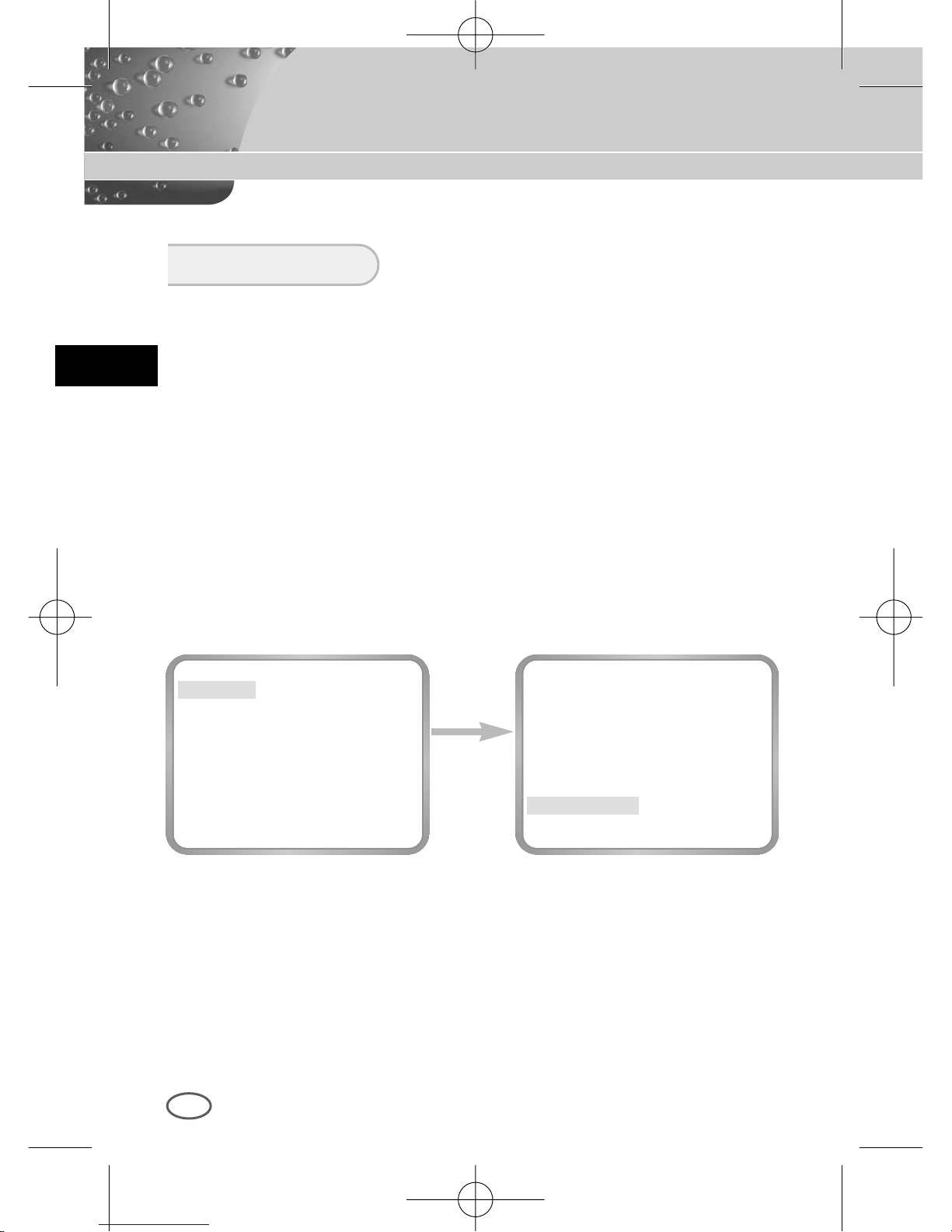
Diese KAMERA ist grundsätzlich je nach Intensität des einfallenden Lichts
die Fuktion gestruert werden und das Niveau des Lichts aufbauen.
❿ ALC
Wenn Sie die BLENDE auf ALC einstellen und [ENTER] drücken, wird
ein Unterbildschirm, wo kann das Niveau des Lichts aufbauen,
eingeblendet.
Der Punkt NIVEAU ermöglicht Ihnen die Lichtsniveau-einstellung mit
Hilfe der Tasten [LINKS, RECHTS].
Es ist möglich, die Lichtsniveau-einstellung nur bei der Verwendung der
DC BLENDE OBJEKTIV.
Es ist möglich, die DC BLENDE Niveau auch bei der Bewegungsmenu
nicht nur bei der Aufbaumenumode.
Wenn Sie die Taste [LINKS] oder [RECHTS] für ca. 2 Sek. drücken,
kommt das Menu des DC BLENDE Lichtsniveau Aufbaus.
Beim Speichern, mit der Taste (LINKS, RECHTS) von AUSGANG zu
SICHERN, dann (ENTER) drücken.
BLENDE
Die Taste
[ENTER]
drücken
KAMERA ID AUS
BLENDE ALC...
BLC AUS
FARBE/S/W FARBE...
SHUTTER AUTO X8
BEWEGUNG S.SCHN
WEISSABGL ATW
SYNC INT
SPEZIAL ...
AUSGANG VERL
(ALC)
DC BLENDE (00) ----I---RUE
00424A SCC-B2307P-GER 4/7/05 9:44 PM ˘`22
Page 65
D
23
❿ ELC
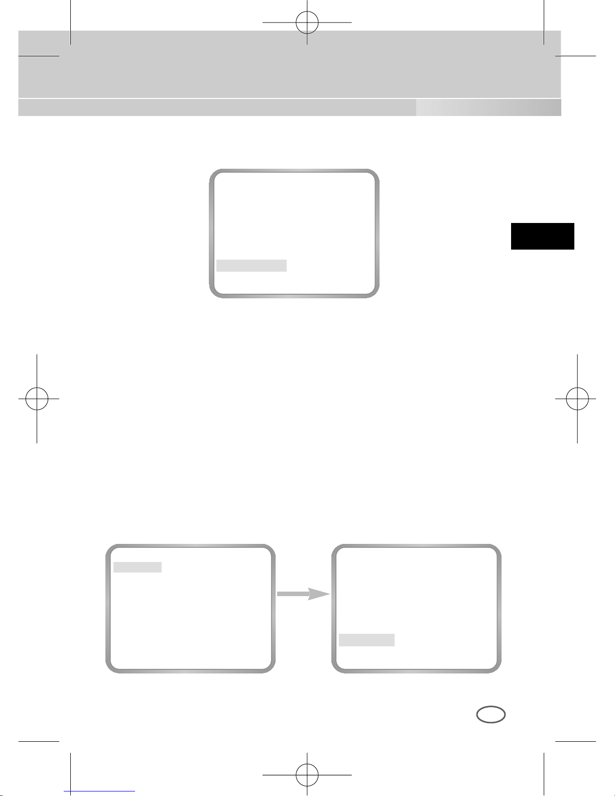
Wenn es zu viele Radiation gibt, dieses Menu kontrolliert automatisch
den hohen Schnelligkeit Verschluß Niveau bei der Verwendung des
manuellen Objektivs und mit dem bestimmten Einstellniveau erhalten
lassen.
Wenn Sie im Menu BLENDE der ELC... wählen und die Taste [ENTER]
drücken, wird das folgende Unterbild erscheinen.
Sie können die Taste [LINKS, RECHTS] pressen, um das Niveau
einzustellen.
Die Taste
[ENTER]
drücken
KAMERA ID AUS
BLENDE ELC...
BLC AUS
FARBE/S/W FARBE...
SHUTTER AUTO X8
BEWEGUNG S.SCHN
WEISSABGL ATW
SYNC INT
SPEZIAL ...
AUSGANG VERL
(ELC)
PEGEL (00) ----I---RUE
DC BLENDE (00) ----I---AUSGANG VERL
00424A SCC-B2307P-GER 4/7/05 9:44 PM ˘`23
Page 66
D
24
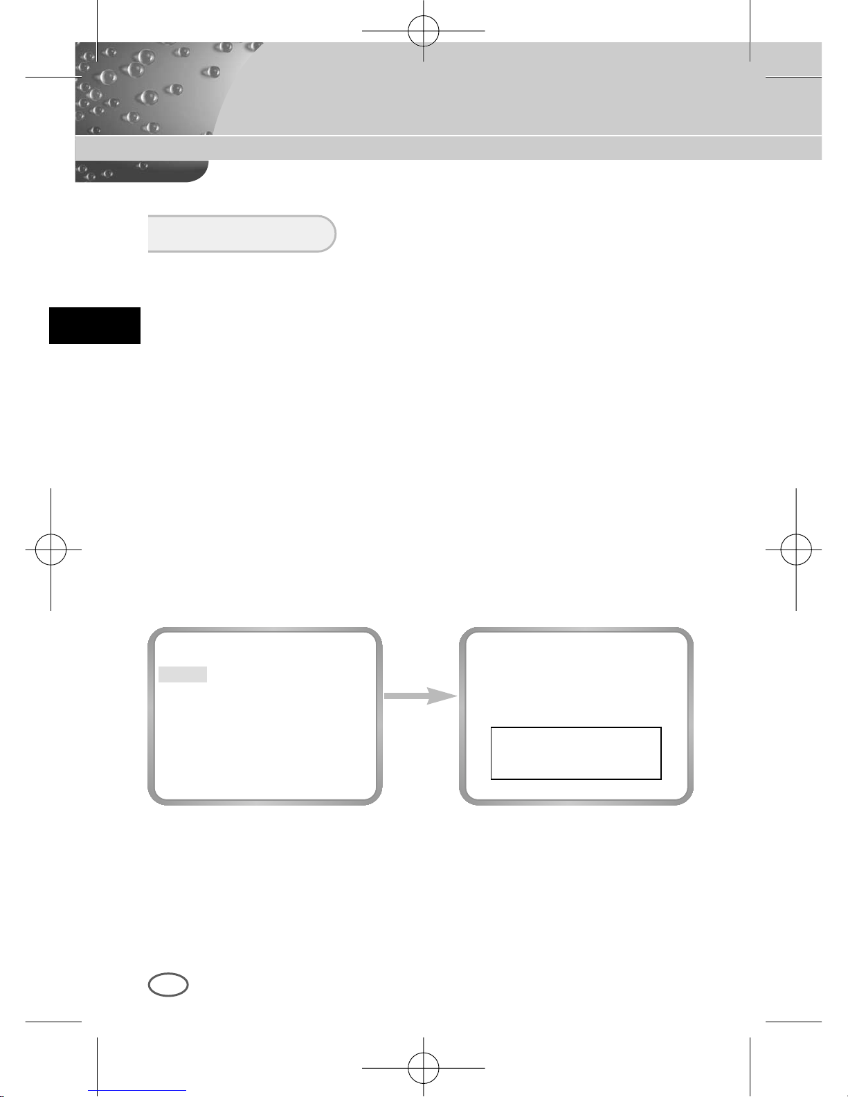
Wird bei einer normalen Kamera eine starke Lichtquelle benutzt, wie z.B.
ein Scheinwerfer, der das Objekt vom hinten beleuchtet, dann erscheint
esauf dem Monitor aufgrund des Gegenlichts dunkel. Zur Lösung des
Gegenlichtproblems kann die passende BLC Funktion so eingestellt
werden, daßbei allen Lichtverhältnissen klare Videobilder gelingen. Mit
Hilfe der Taste LINKS, RECHTS können Sie die 5 bereit eingestellte
Bereich UNTERTEIL..., OBERTEIL...,LINKS..., RECHTS...,MITTE... und
diedirekt einstellbare BENUTZER... Funktion aufbauen.
Im Menu BLC, zB. beim UNTERTEIL... die Taste ENTER drücken, dann
können Sie der eingestellte UNTEN Bereich bestätigen.
BLC
Die Taste
[ENTER]
drücken
KAMERA ID AUS
BLENDE ALC...
BLC UNTEN...
FARBE/S/W FARBE...
SHUTTER AUTO X8
BEWEGUNG S.SCHN
WEISSABGL ATW
SYNC INT
SPEZIAL ...
AUSGANG VERL
00424A SCC-B2307P-GER 4/7/05 9:44 PM ˘`24
Page 67
D
Die Taste
[ENTER]
drücken
Die Taste
[ENTER]
drücken
KAMERA ID AUS
BLENDE ALC...
BLC
BENUTZER...
FARBE/S/W FARBE...
SHUTTER AUTO X8
BEWEGUNG S.SCHN
WEISSABGL ATW
SYNC INT
SPEZIAL ...
AUSGANG VERL
25
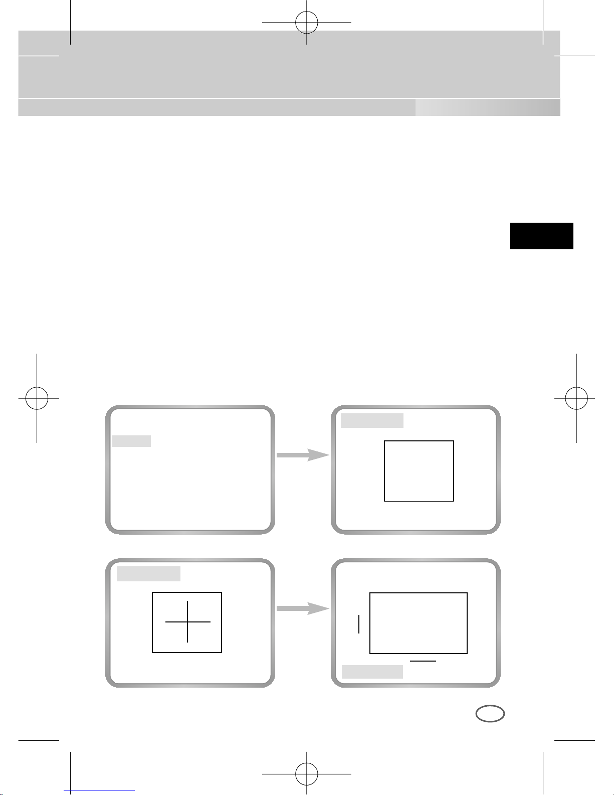
❿ BENUTZER BEREICH
Im Menu BLC mit Hilfe der Taste [LINKS, RECHTS] die Kennung auf
BENUTZER... platzieren, dann können Sie die Größe und die Position
des BLC Bereichs direkt angeben. Wenn der Bereich nicht blinkt, die
Tasten [LINKS, RECHTS, OBEN oder UNTEN] drücken, können Sie die
Größen des Bereichs angeben.
Wenn der Bereich nicht blinkt, die Taste [ENTER] drücken, dann beginnt
der Bereich zu blinken ; Sie können jetzt mit den Tasten [UNTEN,
LINKS, RECHTS, OBEN], die Position des Bereichs festlegen. Durch
erneuten Drücken von [ENTER] verlassen Sie das einstellmenu
BENUTZER BEREICH.
GROESSE..
GROESSE..
GROESSE..
POSITION..
POSITION..
POSITION..
➛❿
❷
❷
➛❿
00424A SCC-B2307P-GER 4/7/05 9:44 PM ˘`25
Page 68
D
26
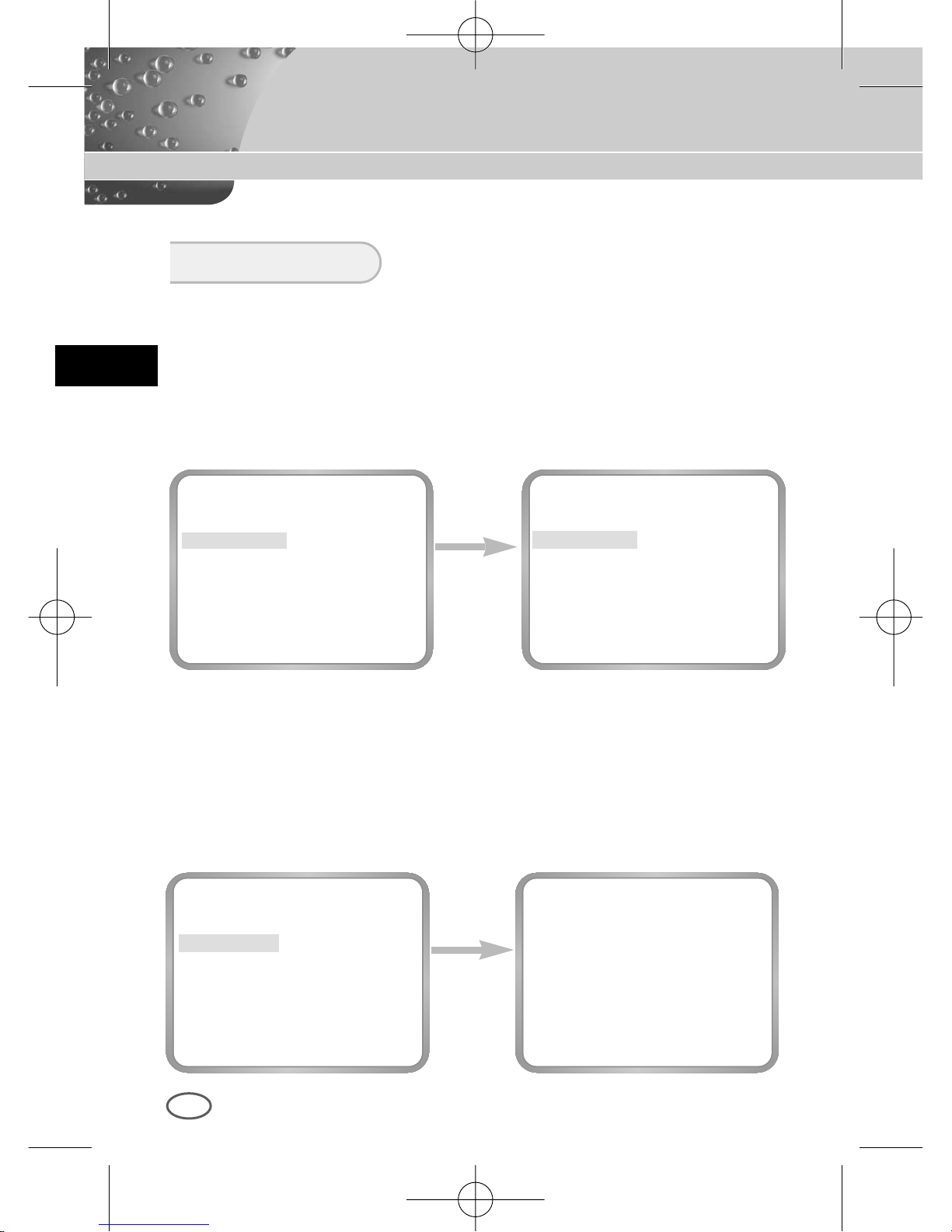
Das FARBE/SW Menu hat eine Funktion, das IR(Infrarot) Filter ein-oder
ausschalten. In niedriger Beleuchtungsumgebung, die SW Mode wird das
IR Filter ausschalten und die Empfindlichkeit wird hoch wie die SW Kamera
sein. Andernfalls, die FARBE Mode wird das IR Filter einschalten und die
Empfindlichkeit wird niedriger mit dem zurückkerten normalen Bild.
FARBE/S/W
Die Taste
[ENTER]
drücken
KAMERA ID AUS
BLENDE ALC...
BLC AUS
FARBE/S/W FARBE...
SHUTTER AUTO X8
BEWEGUNG S.SCHN
WEISSABGL ATW
SYNC INT
SPEZIAL ...
AUSGANG VERL
(FARBE)
GAIN (0)I-------AGC FARBE (0)----I----
RUE
Die Taste
[LINKS/
RESCHTS]
verwenden
KAMERA ID AUS
BLENDE ALC...
BLC AUS
FARBE/S/W FARBE...
SHUTTER AUTO X8
BEWEGUNG S.SCHN
WEISSABGL ATW
SYNC INT
SPEZIAL ...
AUSGANG VERL
❿ FARBE...
Es ist die IR Filter EIN(ON) Mode mit dem normalen Bild. Wenn Sie die
Taste [ENTER] drücken, können Sie das FARBE VERSTÄRKUNG
NIVEAU einstellen und bei der AGC Funktion auch das AGC FARBE.
KAMERA ID AUS
BLENDE ELC...
BLC
BENUTZER...
FARBE/S/W S/W...
SHUTTER AUTO X8
BEWEGUNG S.SCHN
WEISSABGL ATW
SYNC INT
SPEZIAL ...
AUSGANG VERL
00424A SCC-B2307P-GER 4/7/05 9:44 PM ˘`26
Page 69
D
27
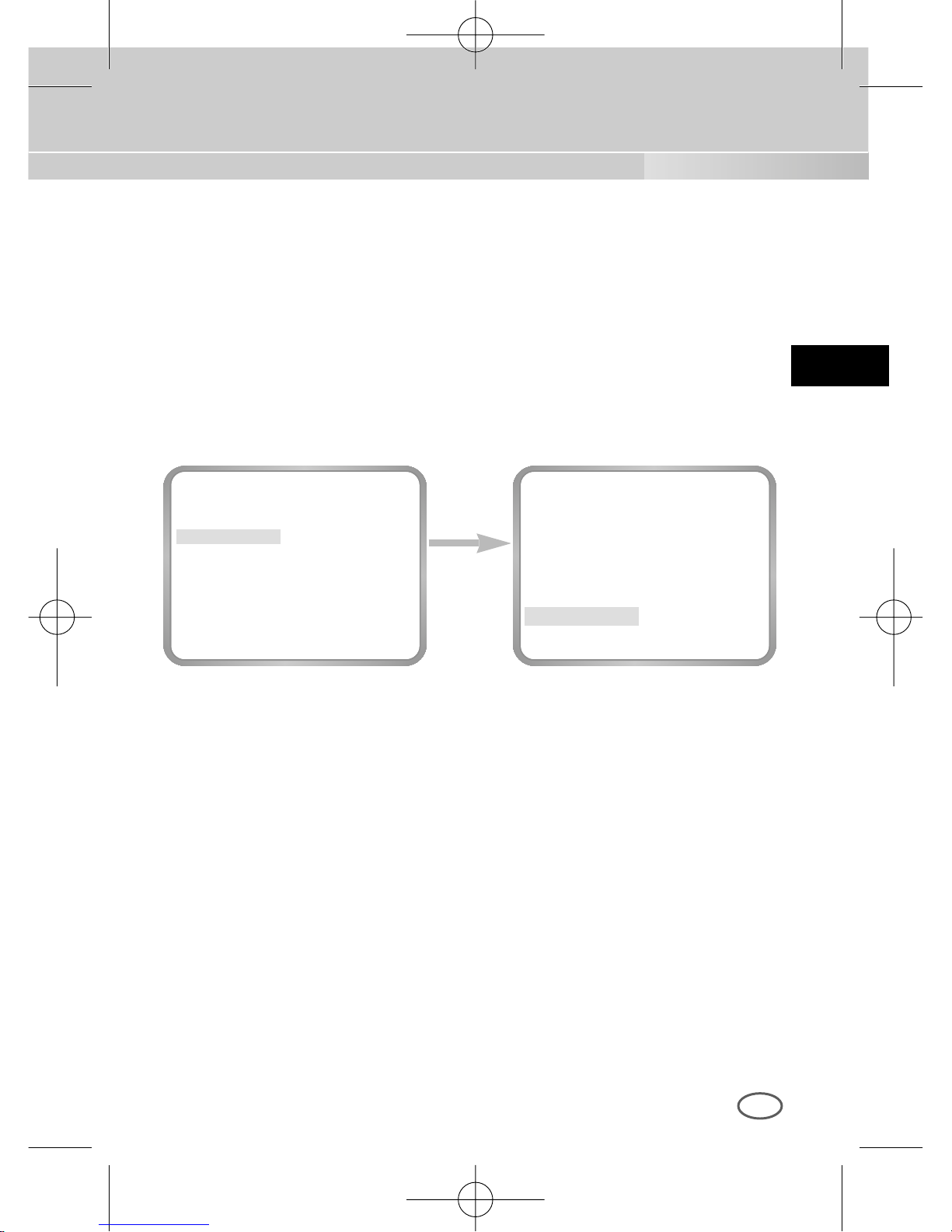
❿ S/W...
Es ist die IR Filter AUS (AUS) Mode in Schwarz und Weiss (hohe
empfindlichkeit wie SW Kamera). Wenn Sie die SW... wählen und die
Taste ENTER drücken, das SW Untermenu erscheint werden.
Sie können einstellen, das BRUCH Signal auszusenden drehend auf
EIN oder AUS.
Die Taste
[ENTER]
drücken
KAMERA ID AUS
BLENDE ALC...
BLC AUS
FARBE/S/W S/W...
SHUTTER AUTO X8
BEWEGUNG S.SCHN
WEISSABGL --SYNC INT
SPEZIAL ...
AUSGANG VERL
(S/W)
F ARBTRAGER
EIN
RUE
00424A SCC-B2307P-GER 4/7/05 9:44 PM ˘`27
Page 70
D
28
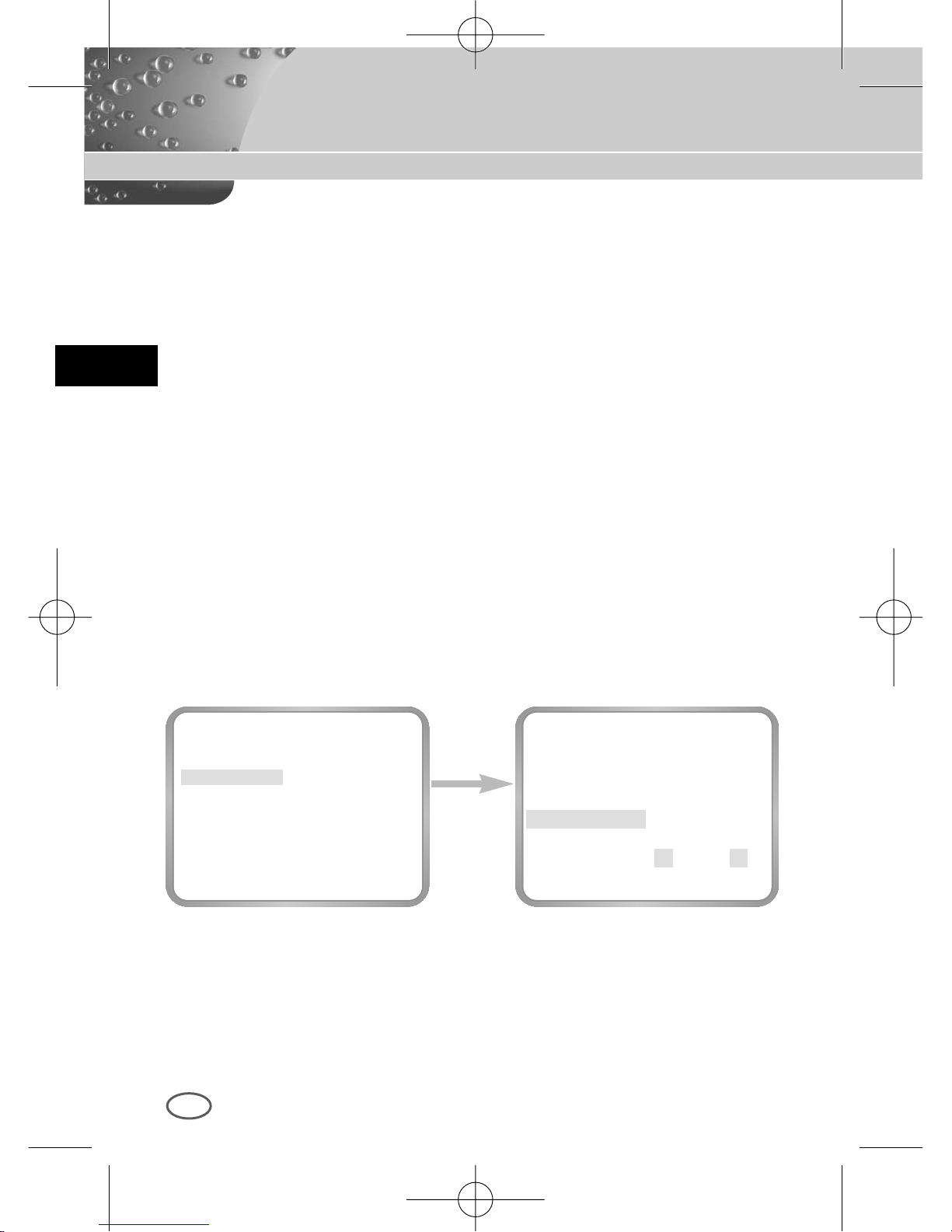
❿ AUTO...
Dieses Menu umwandelt die FARBE mode in der SW Mode automatisch
oder umgekehrt je nach der Beleuchtung. In der niedrigen
Beleuchtungsumgebung, die SW Mode wird das IR Filter ausschalten
und die Empfindlichkeit wird hoch. Andernfalls, in der hohen
Beleuchtungsumgebung, die FARBE Mode wird das IR Filter einschalten
und die Empfindlichkeit wird niedriger.
Wenn Sie das AUTO wählen und die Taste [ENTER] drücken, das
AUTO/SW Unterbild erscheint werden und dieses Bild reguliert das SW
NIVEAU. Sie können das BRUCH Signal drehend auf EIN oder AUS
aussenden, die DAUERZEIT für die Umwandlung einstellen oder das
Standard Beleuchtungsniveau für die Umwandlung die FARBE Mode in
der SW Mode einstellen.
Die Taste
[ENTER]
drücken
KAMERA ID AUS
BLENDE ALC...
BLC AUS
FARBE/S/W AUTO...
SHUTTER AUTO X8
BEWEGUNG S.SCHN
WEISSABGL ATW
SYNC INT
SPEZIAL ...
AUSGANG VERL
(AUTO S/W)
FARBTRAGER
EIN
ZEITRAUM (30S)-I------PEGEL L ----I---- H
RUE
00424A SCC-B2307P-GER 4/7/05 9:44 PM ˘`28
Page 71
D
29
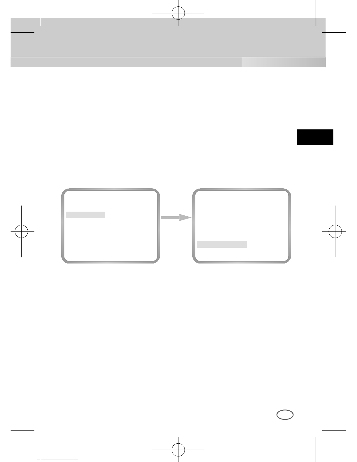
❿ EXT...
Dieses Menu umwandelt die FARBE Mode in der SW Mode automatisch
oder umgekehrt je nach der Beleuchtung mit dem äußeren Sensor.
Wenn Sie das EXT Menu wählen und die Taste [ENTER] drücken, wird
das EXTERNAL S/W Untermenu auf dem Menubild erscheinen.
Sie können das BRUCH Signal drehend auf EIN oder AUS in diesem
Menu aussenden.
Die Taste
[ENTER]
drücken
KAMERA ID AUS
BLENDE ALC...
BLC AUS
FARBE/S/W EXT...
SHUTTER AUTO X8
BEWEGUNG S.SCHN
WEISSABGL ATW
SYNC INT
SPEZIAL ...
AUSGANG VERL
(EXTERN S/W)
FARBTRAGER EIN
RUE
00424A SCC-B2307P-GER 4/7/05 9:44 PM ˘`29
Page 72
D
30
Die Taste
[LINKS/
RESCHTS]
verwenden
KAMERA ID AUS
BLENDE ALC...
BLC AUS
FARBE/S/W FARBE...
SHUTTER AUTO X8
BEWEGUNG S.SCHN
WEISSABGL ATW
SYNC INT
SPEZIAL ...
AUSGANG VERL
KAMERA ID AUS
BLENDE ALC...
BLC AUS
FARBE/S/W FARBE...
SHUTTER AUTO X12
BEWEGUNG S.SCHN
WEISSABGL ATW
SYNC INT
SPEZIAL ...
AUSGANG VERL
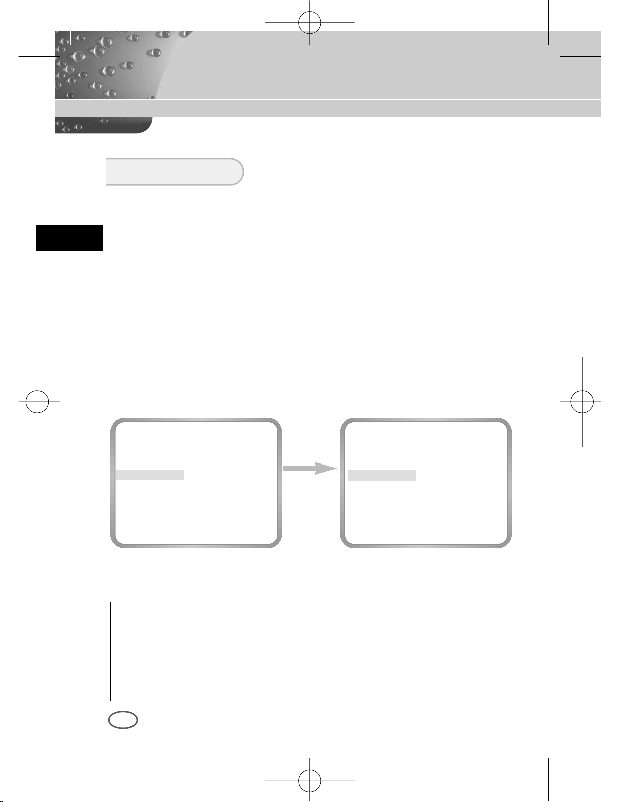
Im Menu VERSCHLUß können Sie die Verschlußzeiten des elektronischen
Schnellverschlußes sowie von AUTO Langsamezeit Verschluß und FEST
Langsamezeit Verschluß festlegen.
Der elektronische Schnellverschluß unterstützt 7 Verschlußzeiten von 1/100
Sekunden bis 1/10K Sekunden, und im allgemeinen ist für das Bild des bewegenden
Objekts benutzt.
Langsamezeit Verschluß und FEST Langsamezeit Verschluß beides unterstützen 12
V erschlußzeiten von x2 bis x128 und hat die Funktion, eine langsamere
V erschlußzeit einzustellen, um ein klares und helles Bild auf dem Monitor zu erhalten.
Wählen Sie AUTO Langsamezeit Verschluß, damit die Kamera die Lichtmenge
ermittelt und je nach Grad der Dunkelheit eine langsame Verschlußzeit automatisch
einstellen möchten. Wählen Sie FEST Menu, um die Verschlußzeit ohne Rücksicht
auf der Monitor-helligkeit einstellen möchten.
Wenn Sie die Richtungstaste LINKS/RECHTS mehrmals drücken,
erscheinen die Verschlußzeiten in der nachstehenden Reihenfolge.
SHUTTER
→
OFF → 1/100(NTSC), 1/120(PAL) → 1/250 → 1/500 → 1/1000 → 1/2000
→
1/4000 → 1/10K → OFF → AUTO X2 → AUTO X4 → AUTO X6 → AUTO X8
→
AUTO X12 → AUTO X16 → AUTO X24→ AUTO X32 → AUTO X48
→
AUTO X64 → AUTO X96 → AUTO X128 → OFF → FEST X2 → FEST X4
→
FEST X6 → FEST X8 → FEST X12 → FEST X16 → FEST X24 → FEST
X32
→
FEST X48 → FEST X64 → FEST X96 → FEST X128
00424A SCC-B2307P-GER 4/7/05 9:44 PM ˘`30
Page 73
D
31
Die Taste
[LINKS/
RESCHTS]
verwenden
KAMERA ID AUS
BLENDE ALC...
BLC AUS
FARBE/S/W FARBE...
SHUTTER AUS
AGC AUS
WEISSABGL ATW
SYNC INT
SPEZIAL ...
AUSGANG VERL
KAMERA ID AUS
BLENDE ALC...
BLC AUS
FARBE/S/W FARBE...
SHUTTER AUS
AGC WENIG
WEISSABGL ATW
SYNC INT
SPEZIAL ...
AUSGANG VERL
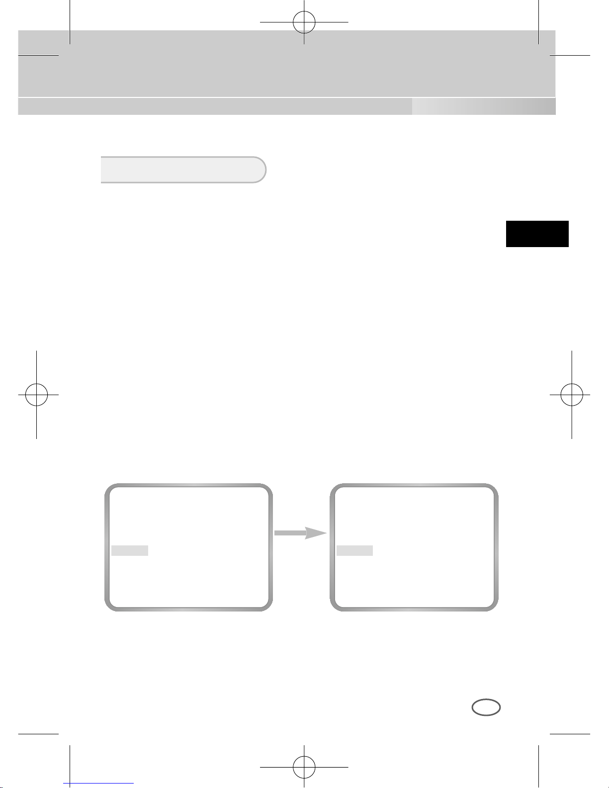
❿ AGC
Das Menu AGC hat die Funktion, das Bild klar zu sehen, wenn das
erhaltene Videobild unter einer bestimmten Helligkeit liegt, weil es bei
unzureichende Licht- verhältnissen aufgenommen wurde. Beim nur
Schnellverschluß oder AUS können Sie das Menu AGC einstellen. Mit
der Taste [LINKS, RECHTS] auf WENIG oder HOCH platzieren, dann
die AGC funktioniert. WENIG wird beim maximalen niedrigen AGC
NIVEAU, HOCH beim höhen AGC NIVEAU verwenden.
Wenn das Menu FARBE / S/W AUTO...ist, wird das Menu AGC als --angezeigt und wird der maximalen AGC GAIN zu HOCH eingestellt.
AGC/BEWEGUNG
00424A SCC-B2307P-GER 4/7/05 9:44 PM ˘`31
Page 74
D
32
Die Taste
[LINKS/
RESCHTS]
verwenden
KAMERA ID AUS
BLENDE ALC...
BLC AUS
FARBE/S/W FARBE...
SHUTTER AUTO X8
BEWEGUNG SCHN
WEISSABGL ATW
SYNC INT
SPEZIAL ...
AUSGANG VERL
KAMERA ID AUS
BLENDE ALC...
BLC AUS
FARBE/S/W FARBE...
SHUTTER AUTO X8
BEWEGUNG S.SCHN
WEISSABGL ATW
SYNC INT
SPEZIAL ...
AUSGANG VERL
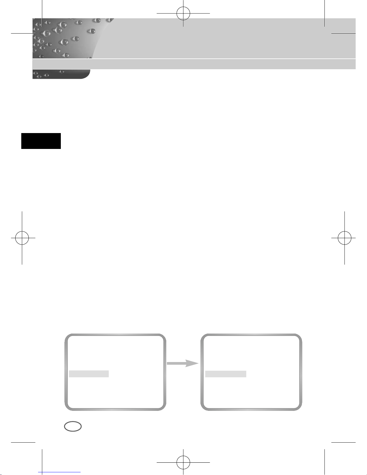
❿ BEWEGUNG
Diese Option kann in der AUTO und FEST Mode benutzt werden;
Es stehen fünf Stufen, S.LANGS, LANGS, NORM, SCHN und S.SCHN
zur Auswahl.
Mit S.LANGS läßt sich die AGC-Verstärkung minimieren, um
unbewegliche Objekte an dunklen Orten überzuwachen.
Mit LANGS läßt sich die AGC-Verstärkung verringern, um wenig
bewegende Objekte an dunklen Orten überzuwachen.
Mit NORM läßt sich die AGC-Verstärkung auf Mitte einstellen, um
bewegende Objekte an dunklen Orten überzuwachen.
Mit SCHN läßt sich die AGC-Verstärkung vergrößern, um sich
schnell bewegende Objekte an dunklen Orten überzuwachen.
Mit S.SCHN läßt sich die AGC-Verstärkung vergrößern, um sich
schnell bewegende Objekte an dunklen Orten überzuwachen.
Ist Verschlußmenu im Einstellmenu AUTO oder FEST eingestellt,
positionieren Sie den Cursor mit der Taste [UNTER] auf BEWEGUNG
Menu und benutzen die Tasten [LINKS, RECHTS], um die Funktion
Bewegung auszuführen.
Bestätigen Sie die Taste [LINKS], um zu LANGS Mode zu gelangen, und
die Taste [RECHTS], um zu SCHN Mode zu gelangen.
00424A SCC-B2307P-GER 4/7/05 9:44 PM ˘`32
Page 75
D
33
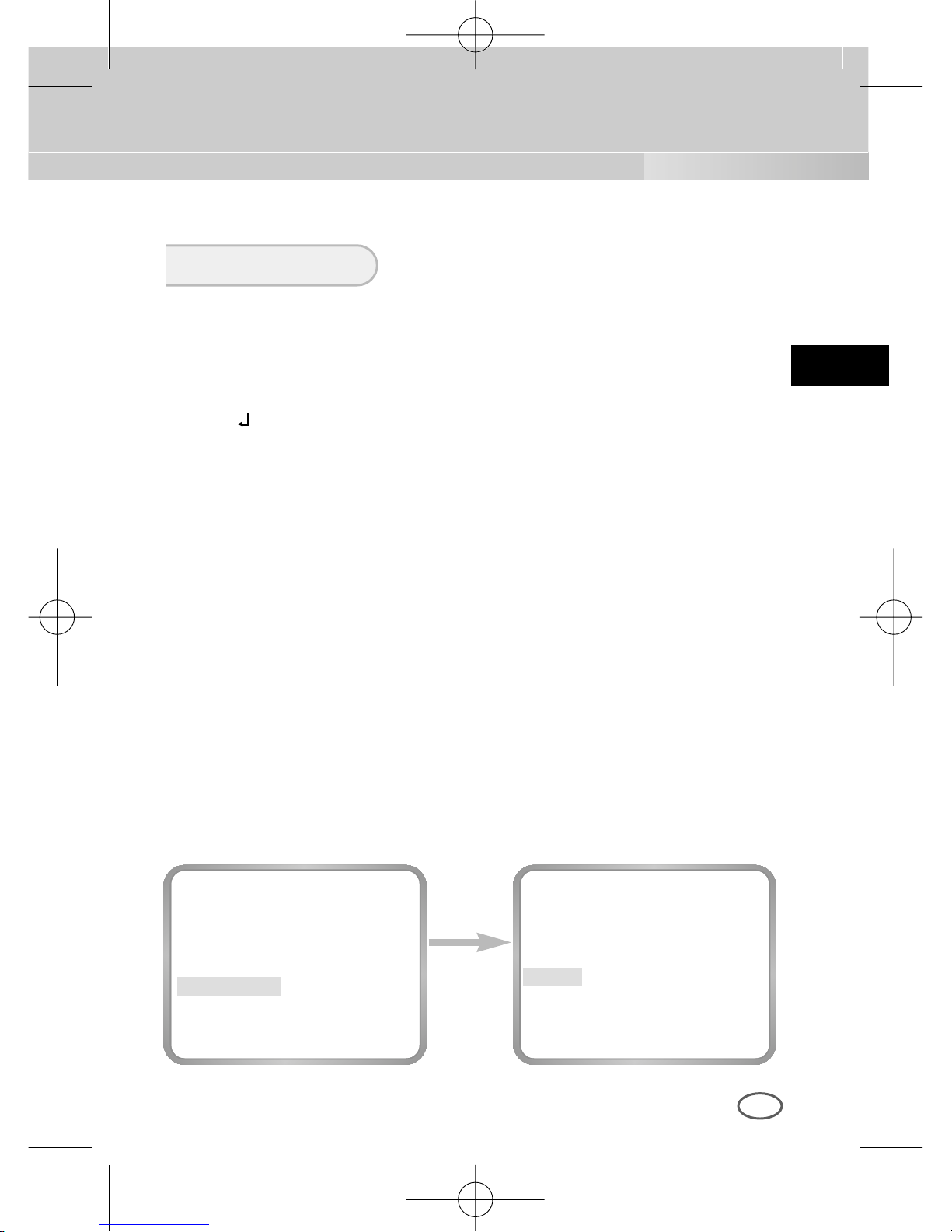
❿ ATW
Wenn Sie WEISSABAL Menu auf A TW Mode einstellen, wacht die Kamera
kontinuierlich die Veränderung der Farbtemperatur über und passt den
Weissabgleich automatisch an die Farbtemperatur an.
❿ AWC
Wenn Das WEISSABAL Menu auf AWC Mode einstellen, wird der Weissabgleich
einmal an die Farbtemperatur angepasst, und dieser Wert wird beibehalten.
Stellen Sie WEISSABAL Menu auf AWC ein und drücken Sie die Taste
[ENTER], dann wird die AWC Funktion ausgeführt.
❿ MANU...
Wenn Sie den WEISSABAL Menu zur MANU... Mode einstellen, können Sie je
nach der bestehende Beleuchtung Weissabgleich direkt ausführen.
Wenn Sie den Punkt MANUELL... auswählen und [ENTER] drücken, wird ein
MANUELL...-Untermenu eingeblendet, in dem Sie einen manuellen
Weissabgleich vornehmen können. Sie haben die Wahl unter 3200°K, 5600°K
oder BENUTZER -Mode, in dem Sie die T asten [LINKS] oder [RECHTS] im
PRESET-Menu drücken.
3200K : Die Farbtemperatur bei 3200°K einstellen.
5600K : Die Farbtemperatur bei 5600°K einstellen.
Benutzer : Unter ROT und BLAU Steuerstab ein geeigneten Wert
auszuwählen, dann die Farbtemperatur einstellen.
WEISSABGL
Die Taste
[ENTER]
drücken
KAMERA ID AUS
BLENDE ALC...
BLC AUS
FARBE/S/W FARBE...
SHUTTER AUTO X8
BEWEGUNG S.SCHN
WEISSABGL MANU...
SYNC INT
SPEZIAL ...
AUSGANG VERL
(AWB/MANU)
PRESET 3200K
RUE
00424A SCC-B2307P-GER 4/7/05 9:44 PM ˘`33
Page 76
D
34
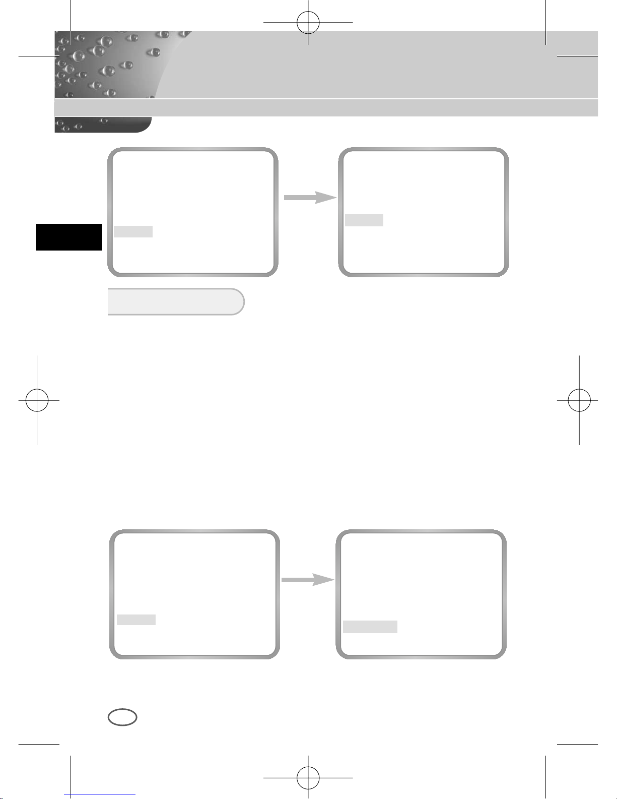
Wählen Sie INT, wenn Sie die interne Synchronisation verwenden. LINIE...
ist für die Synchronisation der Kameraphasen erforderlich, um mehrere
Kameras mit Hilfe des externen Signals (AC Signal) zu betreiben.
Sie können PHASE einstellen, um jegliche Phasenabweichungen zwischen
den einzelnen KAMERA-Sets zu beseitigen.
Diese SYNCH Funktion können Sie bei AC Stromversorgung nutzen;
Positionieren Sie den Cursor auf LINIE..., mit der Taste [LINKS
/
RECHTS].
LINIE. auswählen und [ENTER] drücken, dann erscheint der Bildschrim
eines Untermenus, in dem Sie die Phase-Einstellung anpassen können,
Sie können die Phase von -106H bis +106H einstellen(NTSC), von -138H
bis +138H(PAL).
Bei der DC Stromversorgung Verwendung, erscheint das SYNC Menu
zu ---und die SYNC funktion kann nicht benutzen.
SYNC
Die Taste
[ENTER]
drücken
KAMERA ID AUS
BLENDE ALC...
BLC AUS
FARBE/S/W FARBE...
SHUTTER AUTO X8
BEWEGUNG S.SCHN
WEISSABGL ATW
SYNC INT
SPEZIAL ...
AUSGANG VERL
(LINIE LOCK)
PHASE ( 000) ----I---RUE
Die Taste
[LINKS/
RESCHTS]
verwenden
(AWB/MANU)
PRESET AUS(BENUTZER)
ROT
( 00) ----I----
BLAU
( 00) ----I----
RUE
(AWB/MANU)
PRESET 3200K
RUE
00424A SCC-B2307P-GER 4/7/05 9:44 PM ˘`34
Page 77
D
35
Im Menu SPEZIAL können Sie die Optionen BAUD RATE D-ZOOM, PIP,
SPIEGEL, POSI/NEGA, EINZELHEITEN, BEWEGUNG DET direkt steuern.
Wenn Sie SPEZIAL wählen und [ENTER] drücken, wird ein SPEZIAL Untermenu eingeblendet.
SPEZIAL
Die Taste
[ENTER]
drücken
KAMERA ID AUS
BLENDE ALC...
BLC AUS
FARBE/S/W FARBE...
SHUTTER AUTO X8
BEWEGUNG S.SCHN
WEISSABGL ATW
SYNC INT
SPEZIAL ...
AUSGANG VERL
(SPEZIAL)
BAUD RATE 38400
D-ZOOM AUS
BIB --SPIEGEL AUS
POSI/NEGA +
DETAIL (0)----I-AKTIVITAET AUS
SPRACHE DEUTSCH
RUE
Die Taste
[ENTER]
drücken
(SPEZIAL)
BAUD RATE 38400
D-ZOOM X2
BIB EIN...
SPIEGEL AUS
POSI/NEGA +
DETAIL (0)----I-AKTIVITAET AUS
SPRACHE DEUTSCH
RUE
❿BAUD RATE : Bei der RS232, das Kommunikationstempo auf 4800,
9600, 19200, 38400 bps einstellen.
❿D-ZOOM : Die Vergrößerung ist von 2fach bis 10fach in 5 Schritten
einstellbar.
❿BIB : Bild-in Bild Funktion. Zeigt einen 1/16-großen Bildschirm,
nur bei Verwendung des Digital Zooms. Mit den Tasten
[OBEN, UNTEN, LINKS, RECHTS] können Sie die
Position des BIB Bilds einstellen.
BIB BIldschirm
POSITION..
00424A SCC-B2307P-GER 4/7/05 9:44 PM ˘`35
Page 78
D
36
❿ SPIEGEL : Das Video Ausgangssignal horizontal drehen.
❿ POSI/NEGA : Das Video Helligkeitssignal normal oder umgekehrt
ausgeben.
❿ DTAIL : Die horizontale und vertikale Schärfe regulieren.
❿AKTIVITAET
Die BEWEGUNG DET funktion erkennt sich bewegende Objekte und kann
zur Erkennung von Eindringling bei Abwesenheit eingesetzt werden.
Bei der Bewegung wird das ALARM Signal melden.
Sie können die Bewegungsmelder-empfindlichkeit und den
Bewegungsmelderbereich einstellen.
Wenn Sie EIN wählen und [ENTER] drücken, wird das AKTIVITAET Untermenubild eingeblendet.
❿SPRACHE : Die folgende sprache stehen zur Auswhl: Englich, Deutsch,
Francais, Espanõl und Italiano.
Die Taste
[ENTER]
verwenden
(SPEZIAL)
BAUD RATE 38400
D-ZOOM AUS
BIB --SPIEGEL AUS
POSI/NEGA +
DETAIL (0)----I-AKTIVITAET EIN...
SPRACHE DEUTSCH
RUE
Die Taste
[LINKS/
RECHTS]
verwenden
(SPEZIAL)
BAUD RATE 38400
D-ZOOM AUS
BIB --SPIEGEL AUS
POSI/NEGA +
DETAIL (0)----I-AKTIVITAET AUS
SPRACHE DEUTSCH
RUE
(SPEZIAL)
VITESSE 38400
D-ZOOM AUS
PIP --MIROIR AUS
POSI/NEGA +
DETAIL (0)----I-DET MOUVE AUS
LANGAGE FRANÇAIS
RET
(AKTIVITAET)
BEREICH BENUTZER...
EMPF L ---I--- H
RUE
00424A SCC-B2307P-GER 4/7/05 9:44 PM ˘`36
Page 79
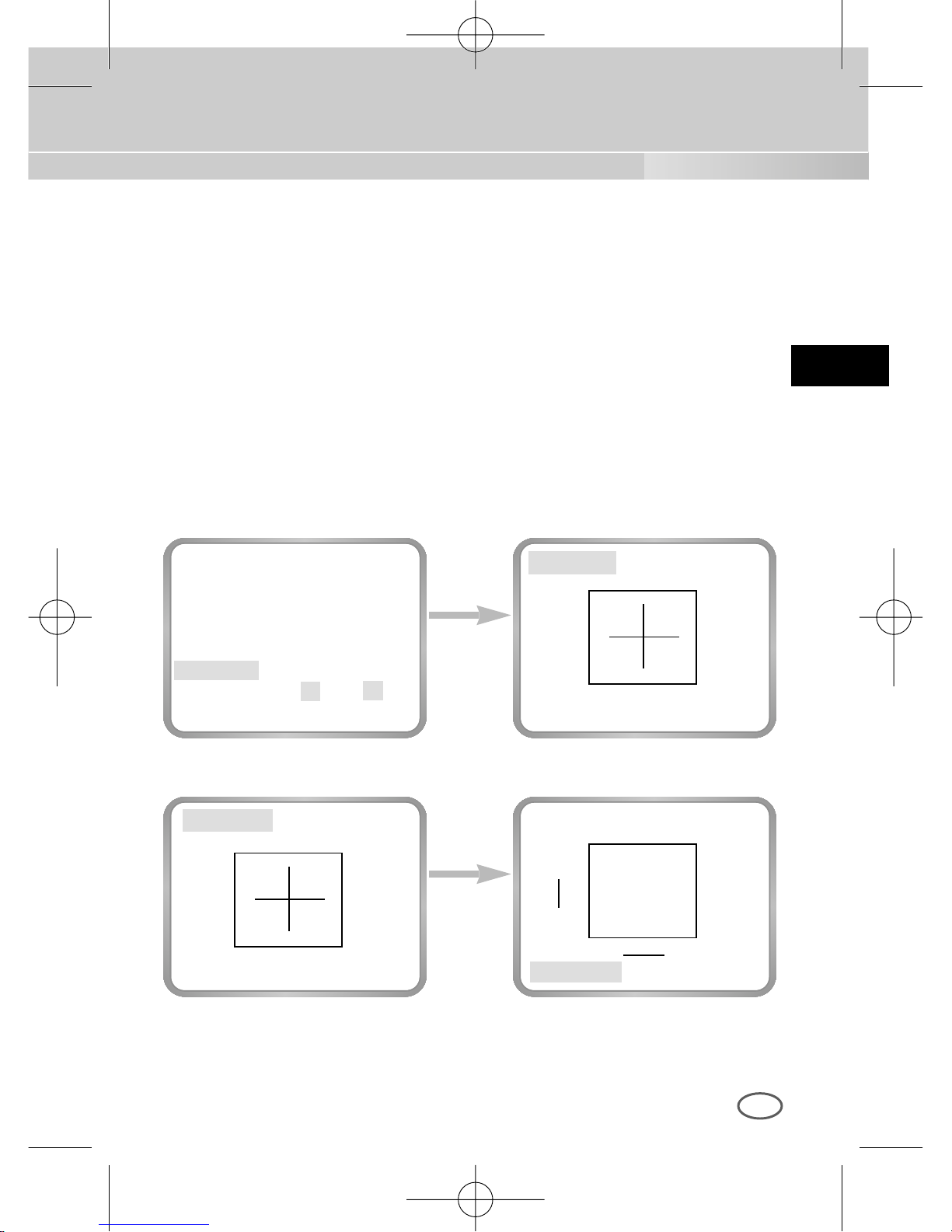
D
37
Das BEREICH menu stellt die Größe und die Position wie der Bereich im
BLC Menu ein. Wenn Sie das Bild-bereich, wo die AKTIVITAET Funktion
eingestellt wird, wählen möchten, müßen Sie die Taste [ENTER] in dem
BEREICH BENUTZER... direkt drücken oder das BEREICH Menu zu
PRESET ... einstellen. Dann die AKTIVITAET Funktion wird auf gewählten
Bereich des Produkts während der Sendung angewendet werden. Sie
können auch den Cursor zum Empfindlichkeit Menu bewegen und die
Tasten [LINKS, RECHTS] drücken, um die Entdeckung der gewählten
Bereichs-bewegung aufzubauen.
Die Taste
[ENTER]
drücken
Die Taste
[ENTER]
drücken
GROESSE..
GROESSE..
POSITION..
POSITION..
POSITION..
GROESSE..
➛❿
❷
❷
➛❿
➛❿
❷
(AKTIVITAET)
BEREICH BENUTZER...
EMPF L ---I--- H
RUE
00424A SCC-B2307P-GER 4/7/05 9:44 PM ˘`37
Page 80
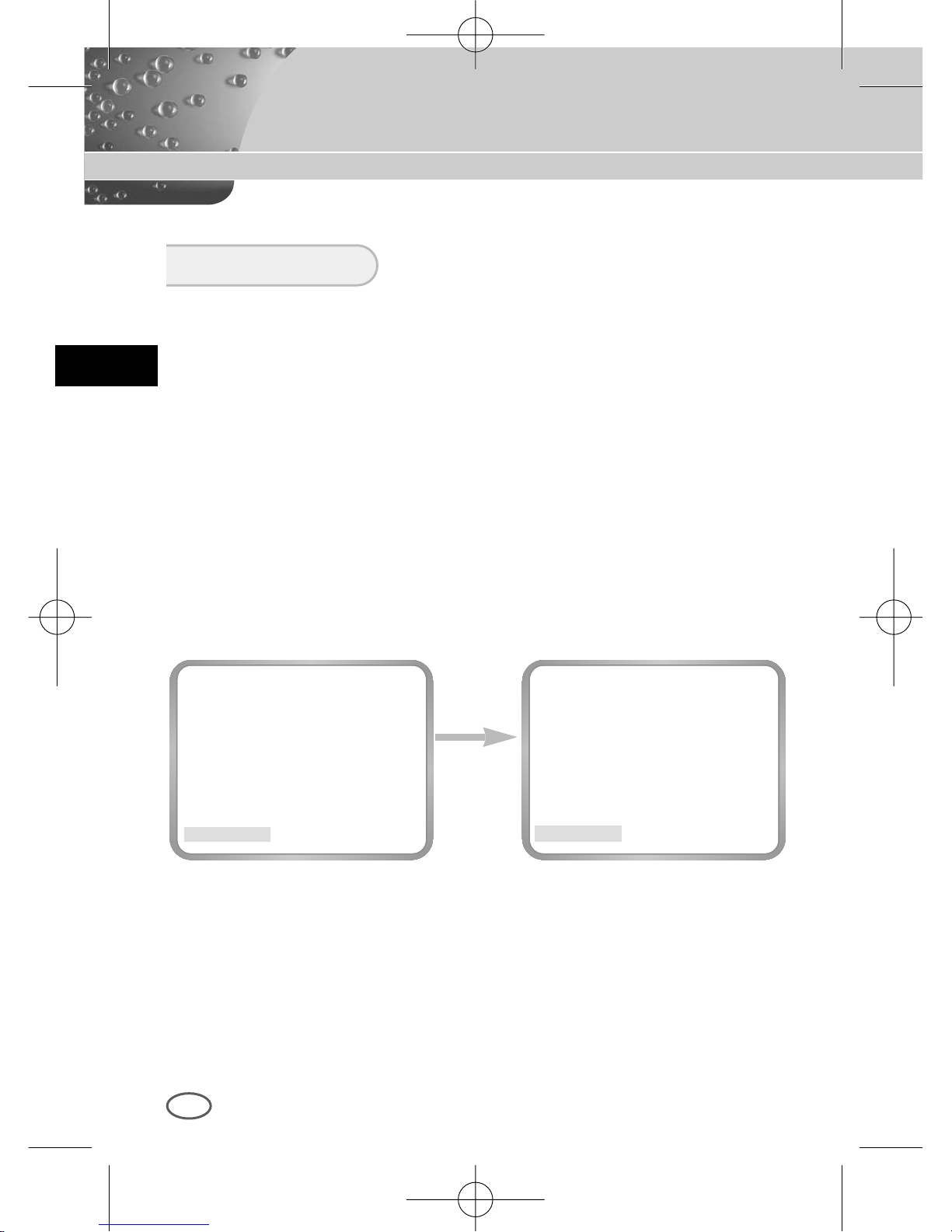
D
38
Die Taste
[LINKS/
RESCHTS]
verwenden
KAMERA ID AUS
BLENDE ALC...
BLC AUS
FARBE/S/W FARBE...
SHUTTER AUTO X8
BEWEGUNG S.SCHN
WEISSABGL ATW
SYNC INT
SPEZIAL ...
AUSGANG VERL
KAMERA ID AUS
BLENDE ALC...
BLC AUS
FARBE/S/W FARBE...
SHUTTER AUTO X8
BEWEGUNG S.SCHN
WEISSABGL ATW
SYNC INT
SPEZIAL ...
AUSGANG SICHERN
Das AUSGANG Menu benutzt für die Beendigung des Kamera Aufbaumenus.
❿ VERL
Übergeht alle von Ihnen vorgenommenen Veränderungen und stellt das
vorherig gespeicherte Einstellmenu wieder her.
❿ SICHERN
Speichert die Einstellmenu, die bisher verändert worden sind.
❿ PRESET
Übergeht alle von Ihnen vorgenommenen Veränderungen und stellt die
wertseitigen KAMERA EINSTELLUNG Menu wieder her.
EXIT
00424A SCC-B2307P-GER 4/7/05 9:44 PM ˘`38
Page 81
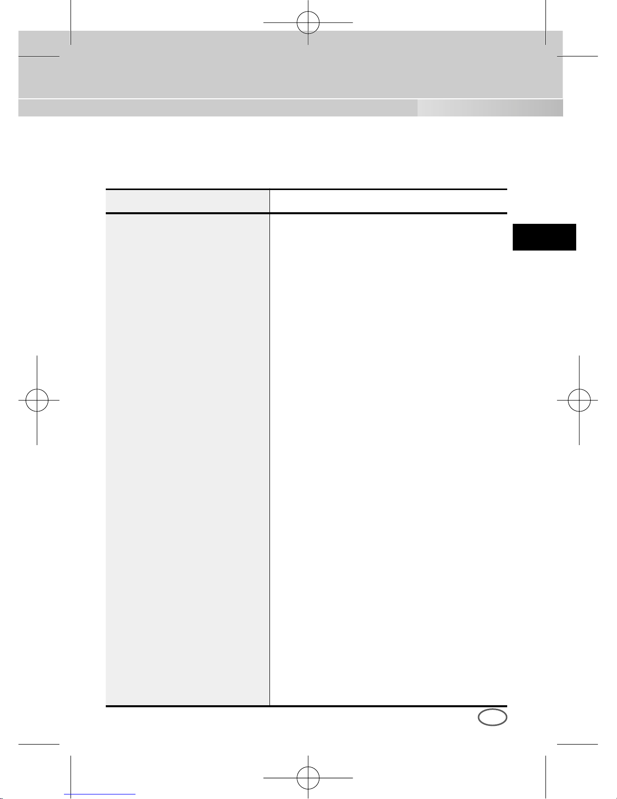
D
39
ARTIKEL BESCHREIBUNG
Definition CCTV Kamera (TAG/NACHT)
Spannungsquelle AC 24V ± 10% (60Hz ±0.1Hz), DC12V+10% ~ -5%
Leistungsaufnahme Approx. 4.5W
Fernsehnorm NTSC Standard Farbe System
Bildaufnehmer 1/3 Inch IT CCD
Effektive Pixel
768 (H) x 494 (V)
Abtastverfahren 525 Linien, 2:1 Zeilensprung
Zeilenfrequenz Horizontal : 15,734 Hz(INT) / 15,750 Hz(L/L)
Vertikal : 59.94 Hz(INT) / 60 Hz(L/L)
Synchronisationsverfahren INT/LINIE Schleuse
Auflösung 500/530 TV Linien (FARBE/S/W)
S/N Ratio 52dB (AGC OFF)
Min.Szenenbeleuchtung FARBE:
0.3 Lux (F1.2) (0.002 Lux)
S/W :
0.06 Lux (F1.2) (0.0004 Lux)
TAG/NACHT
FARBE/S/W/AUTO/EXT
Farbtemperatur ATW/AWC/MANUELL MODE
(3200°K, 5600°K, R/B Verstärkungsregelung)
Elektronische Verschlusszeit ALC:OFF~1/10K sek (7 Stufen)
ELC:Max 1/100K sek
Gegenlichtkompensation AUS/UNTEN/OBEN/LINKS/RECHTS/
MITTE/BENUTZER
Restlichtbetrieb
AUS/AUTO 2x ~ 128x/ FEST 2x ~128x
Digitalzoom
AUS/EIN (x10), BIB
Produkt Spezifikationen
SCC-B2303 Charakteristische Merkmale
00424A SCC-B2307P-GER 4/7/05 9:44 PM ˘`39
Page 82
D
40
ARTIKEL BESCHREIBUNG
Bewegungsmeldung
AUS/EIN(Einstellung von BEREICH/
EMPFINDLICHKEIT)
Videosteuerung Einstellung von POSI/NEGA,SPIEGEL
(LINKS/RECHTS) DETAIL
Signalausgang Composite Videoausgang: 1.0Vp-p 75 ohms/BNC
Objektiv VIDEO / DC
Objektiv Passepartout CS/C (Passepartout Adapter)
Temperatur bei Betrieb -10°C ~ +50°C
Luftfeuchtigkeit bei Betrieb ~ 90%
Abmessungen 68(W) x 55(H) x 128.5 (D)mm
Gewicht Approx. 450g
00424A SCC-B2307P-GER 4/7/05 9:44 PM ˘`40
Page 83
D
41
Prodotto Specificazione
SCC-B2303P/B2003P/B2307P/B2007PCharakteristische Merkmale
ARTIKEL BESCHREIBUNG
Definition CCTV Kamera (TAG/NACHT)
Spannungsquelle SCC-B2303P/B2307P :AC24V±10%
(50Hz±0.1Hz), DC12V+10% ~ -5%
SCC-B2003P/B2007P:AC220V ~ AC240V
(50Hz±0.1Hz)
Leistungsaufnahme SCC-B2303P/B2307P:Approx. 4.5W,
SCC-B2003P/B2007P:Approx.5W
Fernsehnorm PAL Standard Farbe System
Bildaufnehmer SCC-B2303P/B2003P:1/3 inch Super HAD CCD
SCC-B2307P/B2007P:1/3 inch EXview HAD CCD
Effektive Pixel
753 (H) x 582 (V)
Abtastverfahren 625 Linien, 2:1 Zeilensprung
Zeilenfrequenz Horizontal : 15,625Hz(INT) / 15,625 Hz(L/L)
Vertikal : 50 Hz(INT) / 50 Hz(L/L)
Synchronisationsverfahren INT/LINIE Schleuse
Auflösung 500/530 TV Linien (FARBE/S/W)
S/N Ratio 52dB (AGC OFF)
Min.Szenenbeleuchtung SCC-B2303P/B2003P:
Farbe :
0.3 Lux (F1.2) (0.002 Lux)
S/W :
0.06 Lux (F1.2) (0.0004 Lux)
SCC-B2307P/B2007P:
Farbe:
0.2 Lux (F1.2) (0.001 Lux)
S/W:
0.03 Lux (F1.2) (0.0002 Lux)
00424A SCC-B2307P-GER 4/7/05 9:44 PM ˘`41
Page 84
D
42
ARTIKEL BESCHREIBUNG
TAG/NACHT
FARBE/S/W/AUTO/EXT
Farbtemperatur ATW/AWC/MANUELL MODE
(3200°K,5600°K,R/B Verstärkungsregelung)
Elektronische Verschlusszeit ALC:OFF~1/10K sek (7 Stufen)
ELC:Max 1/100K sek
Gegenlichtkompensation AUS/UNTEN/OBEN/LINKS/RECHTS/
MITTE/BENUTZER
Restlichtbetrieb AUS/AUTO 2x ~ 128x/ FEST 2x ~128x
Digitalzoom AUS/EIN (x10), BIB
Bewegungsmeldung
AUS/EIN(Einstellung von
BEREICH/EMPFINDLICHKEIT)
Videosteuerung Einstellung von POSI/NEGA,SPIEGEL
(LINKS/RECHTS) DETAIL
Signalausgang Composite Videoausgang : 1.0Vp-p 75 ohms/BNC
Objektiv VIDEO / DC
Objektiv Passepartout CS/C (Passepartout Adapter)
Temperatur bei Betrieb -10°C ~ +50°C
Luftfeuchtigkeit bei Betrieb - 90%
Abmessungen 68(W) x 55(H) x 128.5 (D)mm
Gewicht SCC-B2303P/B2307P:Approx. 450g,
SCC-B2003P/B2007P:Approx.550g
00424A SCC-B2307P-GER 4/7/05 9:44 PM ˘`42
Page 85
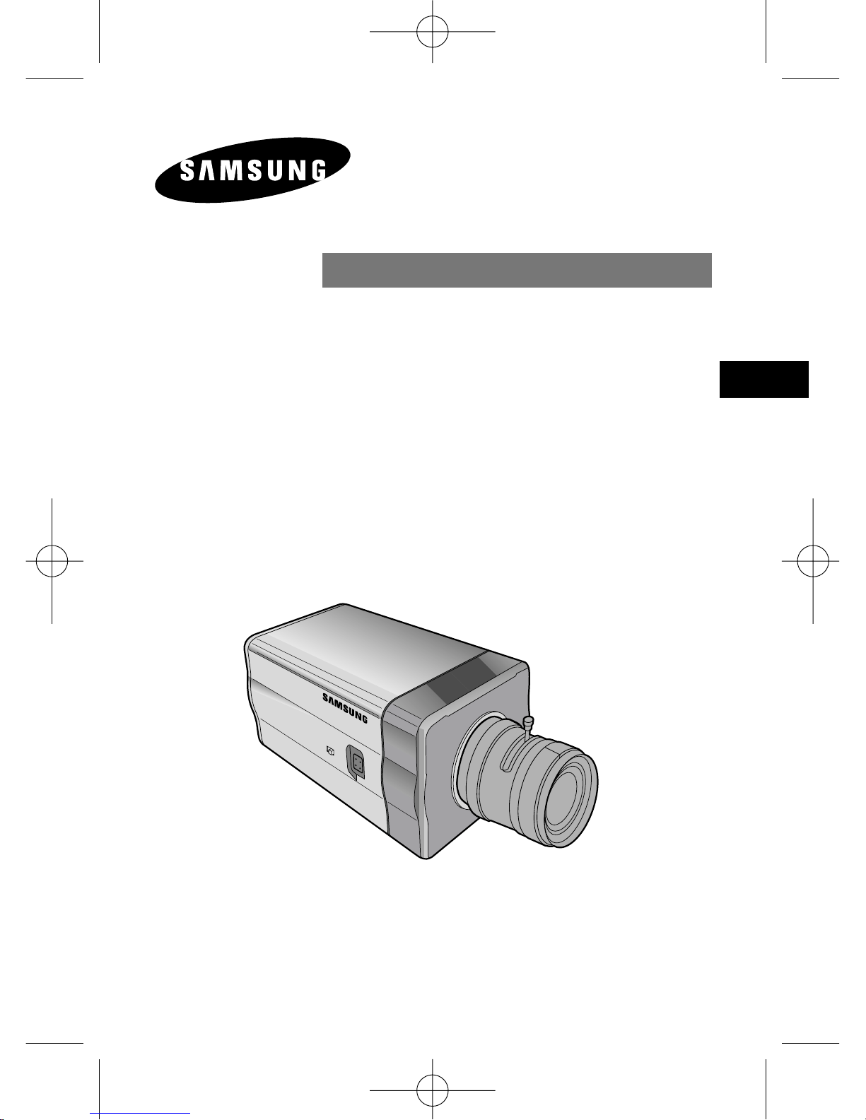
F
CAMERA COULEUR JOUR/NUIT
SCC-B2303(P)/B2003P
SCC-B2307P/B2007P
Manuel d’Utilisation
00424A SCC-B2307P-Fra 4/7/05 9:40 PM ˘`1
Page 86
F
2
Précautions de sécurité
L’objectif des précautions de sécurité est d’assurer l’utilisation correcte de
ce produit afin d’éloigner tout risque et tout dégât à la propriété. Assurezvous de bien observer toutes les précautions.
AvertissementNe pas tenir compte d’un avertissement risque de
causer des blessures graves, voire mortelles.
1. Assurez-vous d’utiliser uniquement l’adaptateur fourni avec le produit.
(L’utilisation d’un adaptateur autre que celui fourni peut endommager le
produit ou causer un incendie ou des décharges électriques.)
2. Avant de brancher le cordon d’alimentation et les câbles de signal, vérifiez
d’abord les bornes extérieures. Reliez les câbles des signaux d’alarme à
leur borne respective. Branchez l’adaptateur CA sur la prise CA et
l’adaptateur CC sur la prise CC tout en tenant compte de la bonne polarité.
(La connexion incorrecte à la source d’alimentation peut endommager le
produit ou causer un incendie ou des décharges électriques.)
3. Ne branchez jamais plus d’une caméra sur un seul adaptateur. (Le
dépassement de la capacité de charge risque de générer une chaleur
anormale au point de causer un incendie.)
4. Branchez le cordon d’alimentation sur la prise murale. Assurez-vous que la
connexion est solidement fixée. (Une mauvaise connexion peut constituer
le risque d’un incendie.)
5. Lorsque vous installez la caméra au mur ou au plafond, assurez-vous
qu’elle y soit fixée solidement et de faáon sécuritaire. (La chute de la
caméra peut causer des blessures corporelles.)
6. Ne placez jamais d’objets conducteurs (p. ex., un tournevis, des pièces de
monnaie, tout autre objet métallique) ni de contenants remplis d’eau sur la
caméra. (Cela pourrait présenter un risque de blessures corporelles en
raison d’un incendie, d’une décharge électrique ou de la chute d’un objet.)
7. N’installez pas la caméra dans un emplacement plein de suie, de poussière
ou d’humidité. Cela pourrait causer un incendie ou provoquer une
décharge électrique.
00424A SCC-B2307P-Fra 4/7/05 9:40 PM ˘`2
Page 87
F
3
8. Si vous détectez une odeur étrange ou de la fumée qui sort du produit,
débranchez immédiatement le cordon d’alimentation et contactez le centre de
soutien technique. (Une sollicitation continue de l’appareil dans ces conditions
pourrait causer un incendie ou provoquer des décharges électriques.)
9. Si ce produit cesse de fonctionner correctement, communiquez avec votre
revendeur ou le centre d’entretien dans votre localité. Ne démontez ni ne
modifiez jamais ce produit. (Samsung n’est pas responsable des problèmes
techniques découlant d’une modification non autorisée ou d’une tentative de
réparation.)
10. Lorsque vous nettoyez le produit, veillez à ne pas vaporiser d’eau directement
sur les composants du produit. (Cela pourrait causer un incendie ou provoquer
une décharge électrique.) Nettoyez la surface au moyen d’un chiffon doux.
N’utilisez jamais de détersifs ni de nettoyants chimiques. Cela pourrait
provoquer une décoloration ou endommager le fini du produit.
Mise en garde
Ne pas tenir compte d’une mise en garde peut entraåner des
blessures cor porelles ou des dégâts à la propriété.
1. Ne laissez pas tomber d’objets sur le produit ni ne soumettez le produit à de
forts coups. Ne placez pas le produit dans un emplacement où il pourrait
subir de fortes vibrations ou des interférences magnétiques.
2. Ne placez pas le produit dans un emplacement où il fait très chaud (plus de
50°C/122°F), très froid (moins de ‘10°C/14°F) ou très humide. (Cela pourrait
causer un incendie ou provoquer une décharge électrique.)
3. Évitez un emplacement où le produit est exposé à des rayons directs du
soleil ou à une source de chaleur, telle qu’un radiateur ou un appareil de
chauffage. (Le non-respect de cette consigne pourrait présenter un risque
d’incendie.)
4. Si vous désirez déplacer le produit à la suite de son installation, assurez-vous
de couper le courant avant son déplacement et sa réinstallation.
5. Installez le produit dans une aire bien ventilée.
6. En cas d’orage, débranchez le cordon électrique de la prise murale. (Le nonrespect de cette consigne pourrait provoquer un incendie ou endommager le
produit.)
00424A SCC-B2307P-Fra 4/7/05 9:40 PM ˘`3
Page 88
F
4
Sommaire
Chapitre 1 Introduction ......................................................... 5
Chapitre 2 Caractéristiques .................................................. 6
Chapitre 3 Noms et Fonctions des Composants ................ 7
Chapitre 4 Installation .......................................................... 12
Précautions d’installation et d’utilisation ............ 13
Raccordement du connecteur de l’objectif à
diaphragme automatique ................................... 14
Fixation de l’objectif / Réglage du bouton de
sélection de l’objectif .......................................... 15
Focalisation ..........................................................16
Connexion du câble .......................................... 18
Chapitre 5 Configuration de la Caméra ............................... 20
Annexe Spécifications Techniques .................................. 39
REMARQUE : Évitez de diriger l’appareil photo directement en direction
d’objets très brillants, tels que le soleil, cela risque d’endommager le
capteur d’image CCD.
00424A SCC-B2307P-Fra 4/7/05 9:40 PM ˘`4
Page 89
5
Chapitre 1 Introduction
F
La caméra JOUR/NUIT est une caméra de surveillance qui
fonctionne en mode couleur jusqu’à une certaine luminosité et
change en dessous de celle-ci son mode de fonctionnement en noir
et blanc en désactivant la fonction ‘IR Cut’. Cela contribue à
améliorer la sensibilité de la caméra en permettant l’identification
des objets même en zone sombre. Sa caractéristique en basse
luminosité est hautement renforcée par la fonction ‘Sense Up’ dû à
l’obturateur à basse vitesse et au mode d’accumulation ‘Field’.
La caméra JOUR/NUIT est conçue pour une application en zone
sombre comme dans les parkings souterrains où la luminosité est
en dessous d’un certain seuil. Elle fonctionne en mode couleur en
offrant une haute résolution horizontale de 480 lignes dans la
journée et elle peut capter des objets même dans la nuit en
appliquant la fonction JOUR/NUIT et la fonction ‘Sense Up’. Vous
pouvez également utiliser cette caméra avec l’émetteur d’infrarouge.
[Fonction JOUR/NUIT]
En dessous d’une certaine luminosité, le filtre coupant les
infrarouges (IR Cut) est désactivé afin d’améliorer la
sensibilité de la caméra.
00424A SCC-B2307P-Fra 4/7/05 9:40 PM ˘`5
Page 90
6
Chapitre 2 Caractéristiques
F
Haute sensibilité
La technologie de pointe ‘1/3" Super(EXview)-HAD IT CCD’ permet
d’obtenir des images d’une haute sensibilité.
Fonctionnement en basse luminosité
Le fonctionnement en basse luminosité basé sur la technologie du signal
numérique et la fonction JOUR/NUIT offre une possibilité de prise de vue
même sous de mauvaises conditions sans lumière.
Zoom numérique
La caméra dispose d’un zoom de 10x au maximum grâce à la fonction de
zoom numérique. (Si vous activez la fonction PIP sur le mode de zoom
numérique, l’écran entier s’affiche en PIP.)
Excellente correction du contre-jour
Malgré la présence d’un éclairage puissant ou d’un rayonnement solaire
derrière l’objet, cette caméra permet d’obtenir une prise de vue nette grâce
à la correction des images assombries par le contre-jour.
Mode de synchronisation numérique
Le mode de synchronisation numérique des fréquences trame et réseau est
intégré dans cette caméra pour un réglage direct de la synchronisation
verticale de la caméra, permettant un contrôle plus pratique et fiable.
Résolution
La caméra offre une haute résolution grâce à une technologie ultramoderne
de traitement numérique des images.
Sélection du signal de sortie
Il est possible d’inverser le signal de sortie vidéo et de régler le profil
horizontal et vertical.
00424A SCC-B2307P-Fra 4/7/05 9:40 PM ˘`6
Page 91
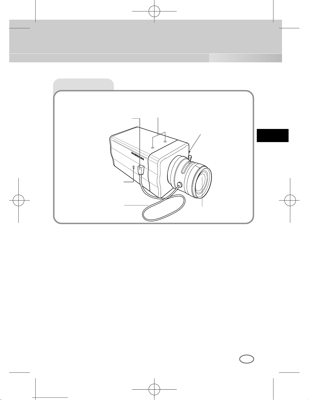
7
Chapitre 3 Noms et Fonctions des Composants
F
Vue de côté
Encoche pour la fixation sur le support d’installation
Utilisez cette encoche pour fixer la caméra avec des vis sur le support
d’installation constituant une partie de l’équerre sur laquelle la caméra sera
installée.
Objectif à diaphragme automatique (option)
Ceci est un objectif à fixer sur la caméra.
* Si la surface de l’objectif est sale, nettoyez-la délicatement avec un tissu
spécifique pour l’optique ou un tissu de coton humidifié à l’éthanol.
Connecteur de l’objectif à diaphragme automatique
Ce connecteur fournit au diaphragme de l’objectif l’alimentation, le signal de
contrôle, le signal vidéo ou le signal DC nécessaires à son contrôle.
Câble de contrôle de
l’objectif à diaphragme
automatique
Bouton de sélection
de l’objectif ALC
Connecteur de l’objectif à
diaphragme automatique
Objectif
Barre de focalisation
Encoche pour la fixation
sur le support d’installation
00424A SCC-B2307P-Fra 4/7/05 9:40 PM ˘`7
Page 92
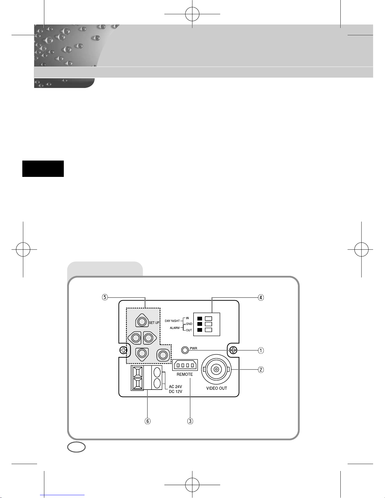
F
8
Câble de contrôle de l’objectif à diaphragme automatique
Ce câble transmet le signal de contrôle émis par la caméra pour contrôler
le diaphragme de l’objectif.
Barre de focalisation
Utilisez cette barre pour la focalisation.
Bouton de sélection de l’objectif ALC
Utilisez ce bouton pour sélectionner le type d’objectif à diaphragme
automatique souhaité.
DC : Positionnez ce bouton sur DC si vous avez installé un objectif à
diaphragme automatique nécessitant un signal de contrôle DC.
VIDEO : Positionnez ce bouton sur VIDEO si vous avez installé un objectif
à diaphragme automatique nécessitant un signal de contrôle VIDEO.
Vue arrière
00424A SCC-B2307P-Fra 4/7/05 9:40 PM ˘`8
Page 93
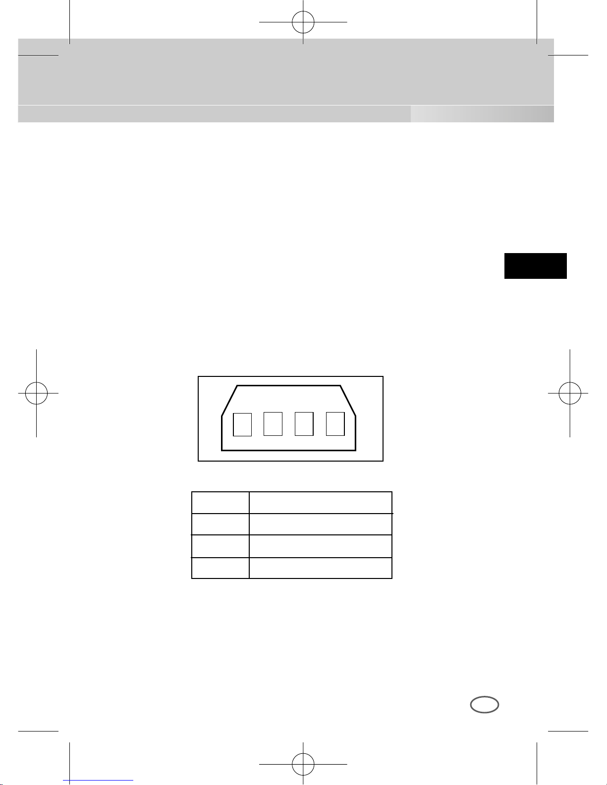
F
9
① LED de l’alimentation
La LED s’allume lorsque l’alimentation fonctionne.
➁ Sortie vidéo
Cette sortie est reliée à l’entrée vidéo du moniteur et donne le signal
vidéo de la caméra.
➂ Entrée REMOTE (RS-232)
Cette entrée est utilisée pour le réglage de la caméra en usine.
1 TXD
2 RXD
3 +5V
4 GND
1
2 3 4
00424A SCC-B2307P-Fra 4/7/05 9:40 PM ˘`9
Page 94
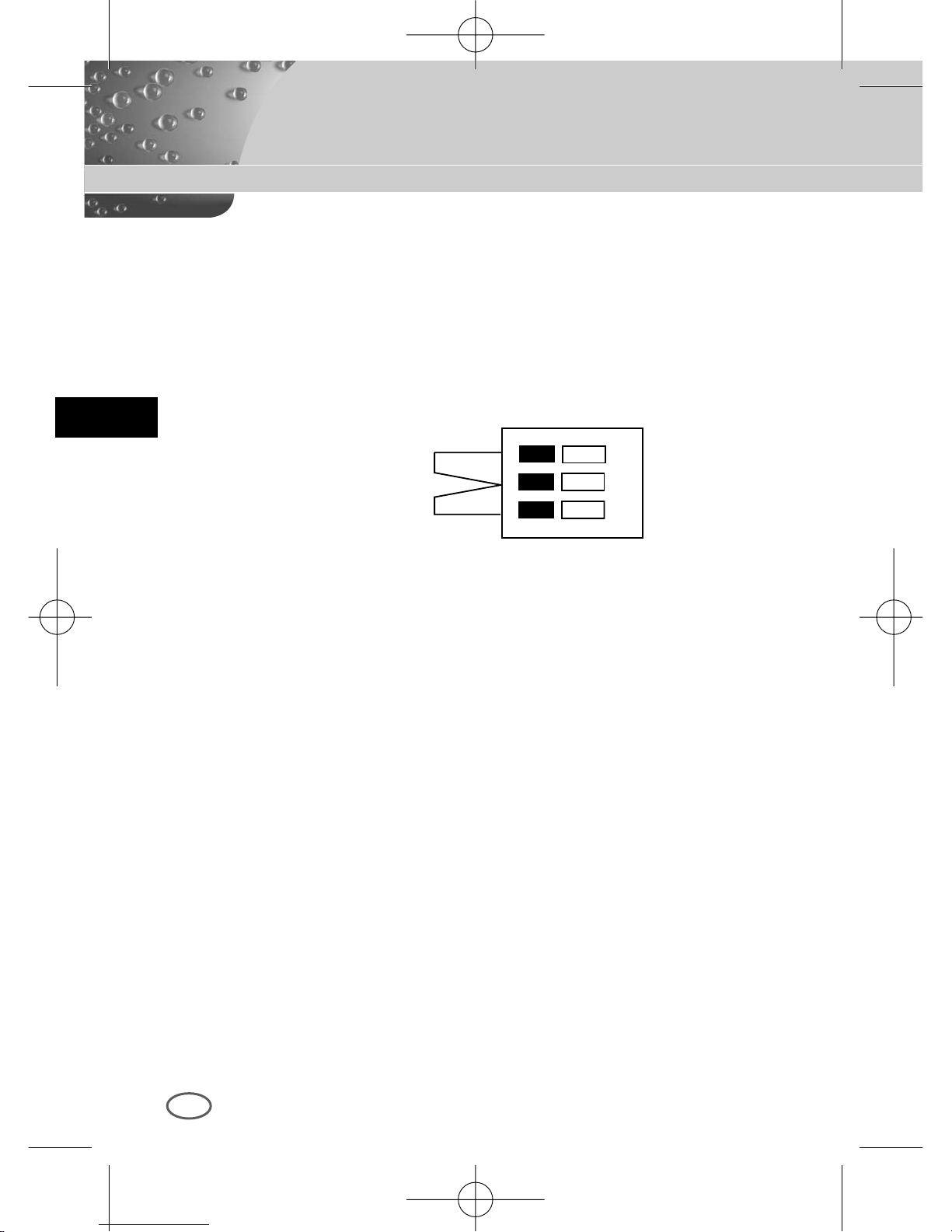
F
10
➃ Entrée de signal externe JOUR/NUIT & sortie de signal d’alarme
C’est une fonction qui permet de recevoir le signal externe JOUR/NUIT
émis par un détecteur de luminosité externe (option) et de changer le
mode de fonctionnement en noir et blanc. Lorsque la fonction
‘MOUVEMENT DET’ est activée, le signal d’alarme est émis suite à une
détection de mouvement.
①
➁
DAY/NIGHT IN
GND
ALARM OUT
Reliez le détecteur externe au terminal JOUR/NUIT comme le montre la
figure ① , puis reliez l’équipement externe tel que sonnerie ou lampe au
terminal d’alarme comme le montre la figure ➁.
La sortie d’alarme est un collecteur ouvert de puissance : inférieur DC 16V
/ inférieur 100mA.
OFF : contact ouvert
ON : inférieur à 100mA
L’entrée JOUR/NUIT est de DC 5V pull-up et supérieur à 0,2mA.
OFF : contact ouvert
ON : contact fermé
00424A SCC-B2307P-Fra 4/7/05 9:40 PM ˘`10
Page 95
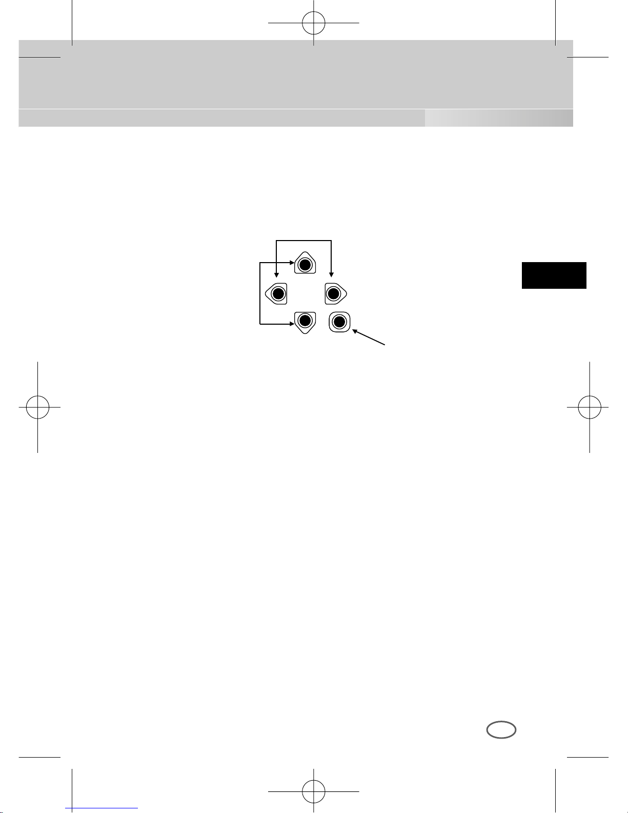
F
11
⑤ Bouton de réglage de la caméra (Setup)
Les fonctions de contrôle de la caméra varient selon le mode utilisé :
mode standard (le menu Setup ne s’affiche pas sur l’écran) ou mode
Setup.
Mode standard
Touches [Gauche/Droite] : Appuyez pendant 2 secondes sur les
touches Gauche/Droite pour accéder au
menu de réglage du niveau ‘DC IRIS’. La
touche [gauche] diminue le niveau
‘DC IRIS’ et la touche [droite] l’augmente.
Touche [ENTER] : Appuyez sur cette touche (pendant plus de 2
secondes) pour entrer dans le menu Setup.
Mode Setup
Touches [Haut/Bas] : Utilisez ces touches pour déplacer le curseur
vers le haut ou le bas.
Touches [Gauche/Droite] : Utilisez ces touches pour déplacer le
curseur vers la gauche ou la droite, ou pour
afficher dans l’ordre les valeurs ajustables
de chaque menu Setup
Touche [ENTER] : Utilisez cette touche pour accéder au sous-menu
Setup ou pour sélectionner la valeur actuelle.
➅ Port d’alimentation secteur
Ce port est connecté au cordon (à la prise) d’alimentation.
Touches
[Gauche/Droite]
Touche [ENTER]
Touches
[Haut/Bas]
00424A SCC-B2307P-Fra 4/7/05 9:41 PM ˘`11
Page 96
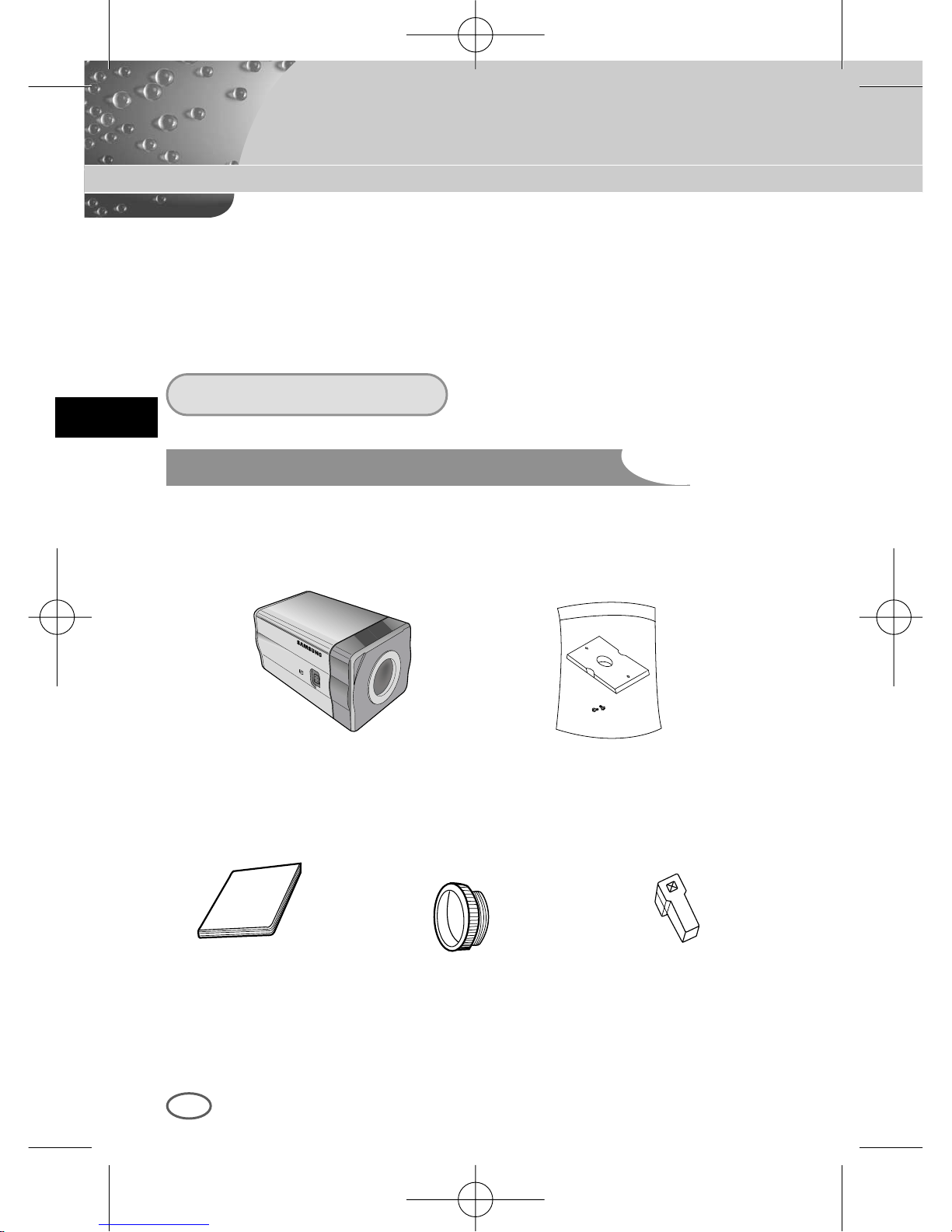
12
Chapitre 4 Installation
F
Ce chapitre contient des informations relatives aux vérifications avant
l’installation de la caméra, au choix de sa mise en place et aux précautions
d’installation. Veuillez lire attentivement ces indications avant d’installer la
caméra et de connecter le câble
Vérifiez que les éléments suivants sont inclus dans l’emballage.
Avant l’installation
Lors du déballage, vérifiez le contenu du paquet :
Caméra Adaptateur (‘Mount’)
Adaptateur ‘C Mount’ Connecteur de
l’objectif à diaphragme
automatique
Manuel d’utilisation
00424A SCC-B2307P-Fra 4/7/05 9:41 PM ˘`12
Page 97
F
13
① La caméra de doit pas être démontée par l’utilisateur lui-même.
➁ Veuillez toujours utiliser la caméra avec précaution. Evitez les chocs, les
secousses, un stockage sans soin et une mauvaise manipulation qui
peuvent endommager la caméra.
➂ N’installez pas la caméra sous la pluie ou dans des endroits humides.
➃ Utilisez un tissu sec pour le nettoyage. Ne frottez pas excessivement le
corps de la caméra avec des produits abrasifs.
⑤ Installez la caméra dans un endroit frais en évitant le rayonnement direct
du soleil car celui-ci peut endommager l’appareil.
Précaution d’installation et d’utilisation
00424A SCC-B2307P-Fra 4/7/05 9:41 PM ˘`13
Page 98
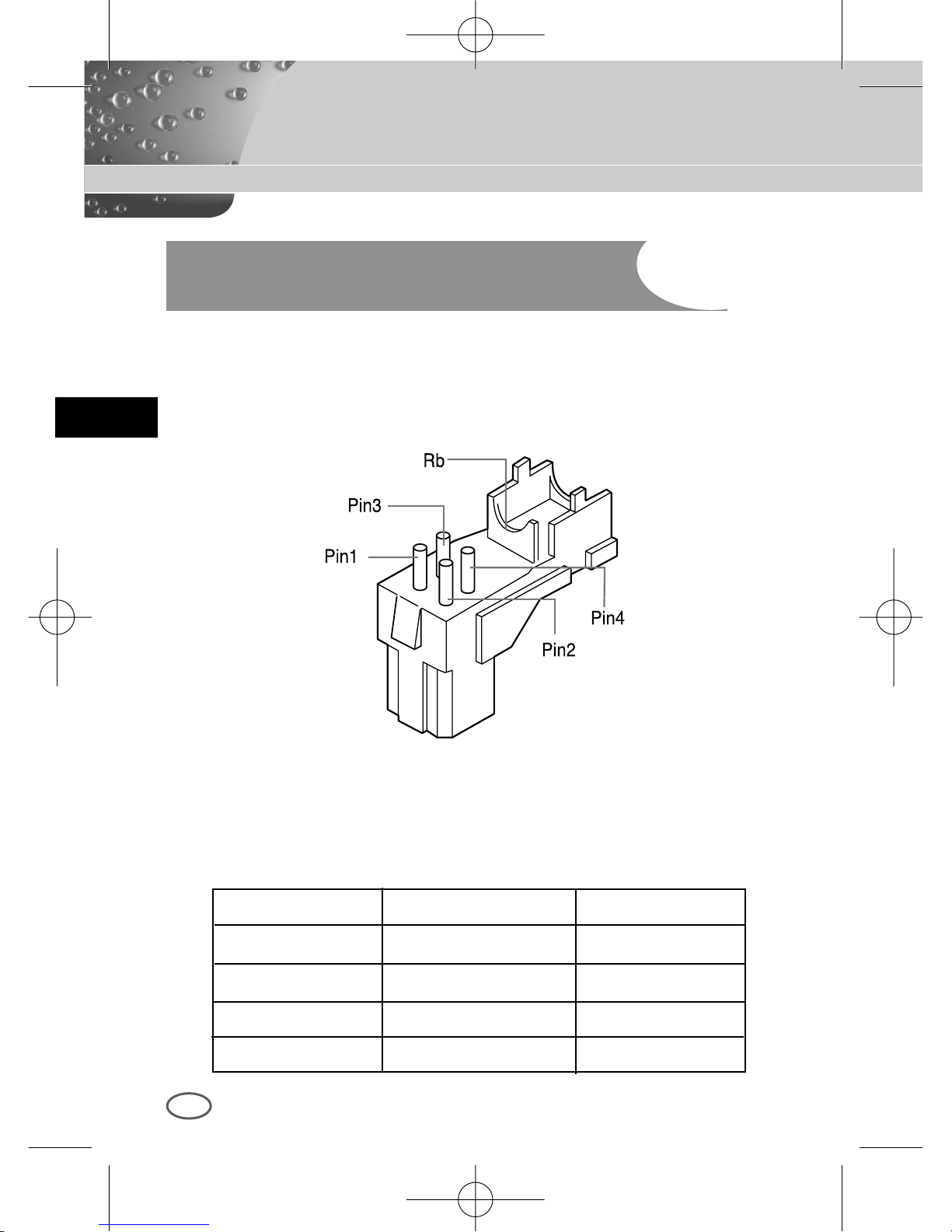
F
14
Raccordement du connecteur de l’objectif à
diaphragme automatique
Préparez le connecteur de l’objectif à diaphragme automatique fourni avec la
caméra.
Otez la protection des câbles de contrôle du diaphragme et reliez chaque
câble au connecteur de l’objectif du diaphragme automatique en vous
référant au tableau suivant :
N° de la clé Type de contrôle DC Type de contrôle VIDEO
1 Damp (-) Alimentation (+12V)
2 Damp (+) Non utilisé
3 Drive (+) Signal VIDEO
4 Drive (-) GROUND
00424A SCC-B2307P-Fra 4/7/05 9:41 PM ˘`14
Page 99
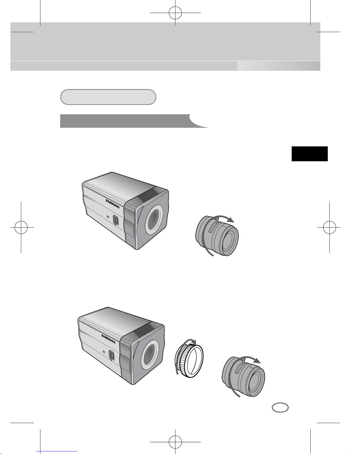
F
15
Installation
Fixation de l’objectif
Lors de l’objectif CS :
Vissez l’objectif CS dans le sens des aiguilles d’une montre, comme
l’indique la figure ci-dessous.
Lors de l’objectif C :
Vissez d’abord le support d’installation dans le sens des aiguilles d’une
montre. Vissez ensuite l’objectif C dans le même sens, comme l’indique
la figure ci-dessous.
l’objectif CS
l’objectif C
00424A SCC-B2307P-Fra 4/7/05 9:41 PM ˘`15
Page 100
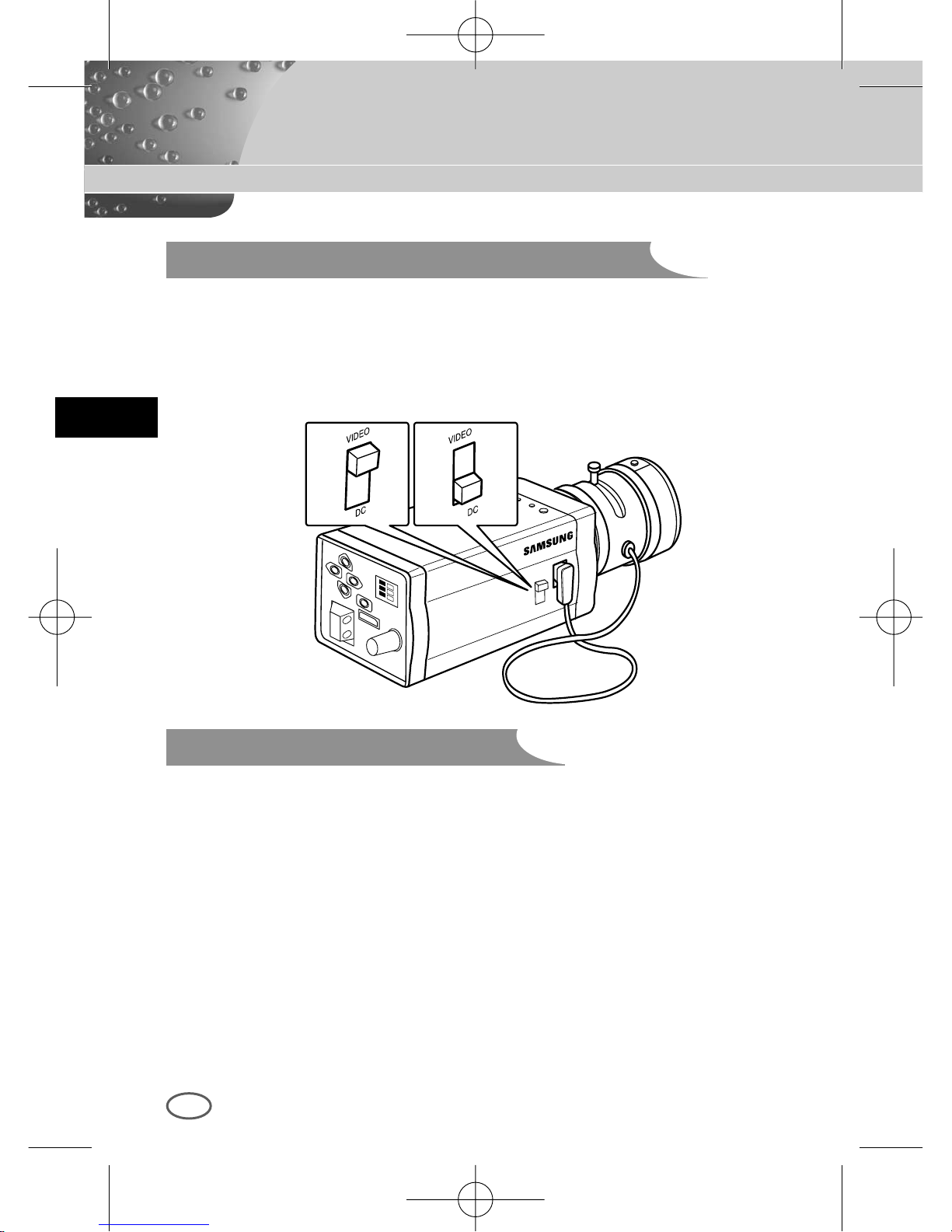
F
16
Réglage du bouton de sélection de l’objectif
Focalisation
Vous devez régler le bouton de sélection de l’objectif situé sur le côté de la
caméra selon le type d’objectif. Positionnez le bouton sur « DC » si
l’objectif fixé est de type contrôle DC, et sur « VIDEO » si l’objectif fixé est
de type contrôle VIDEO.
La focale de la caméra est déjà réglée en sortie d’usine, mais cette
focalisation peut ne pas correspondre à certains types d’objectif. Dans ce
cas, réglez la focale selon les indications suivantes. Ceci est une méthode
pour le réglage d’un objectif à focale fixe.
Objectif sans fonction de zoom
① Prenez l’image d’un objet net (en forme de carreau) placé à une
distance de plus de 10 m et positionnez l’anneau de la focale de
l’objectif sur l’infini (∞).
➁ Tournez-le jusqu’à ce que l’image de l’objet soit la plus nette possible.
➂ Fixez l’anneau de réglage de la focale en serrant la vis.
00424A SCC-B2307P-Fra 4/7/05 9:41 PM ˘`16
 Loading...