

SAMSUNG AWH126JE0K Service Manual
ROOM AIR CONDITIONER
FANCOOLHEATDEICE
POWER / MODE
°C
Hour
AWH126JE
AWH127JE
Manual
SERVICE
AIR CONDITIONER CONTENTS
1. Precautions
2. Product Specifications
3. Installation and Operating
Instructions
4. Disassembly and Reassembly
5. Troubleshooting
6. Exploded Views and Parts List
7. Block Diagram
8. PCB Diagram
9. Wiring Diagram
10. Schematic Diagrams

ELECTRONICS
Samsung Electronics Co., Ltd. MAR. 1998.
©
Printed in Korea.
Code No. DB81-10152A

1. Precautions
1. Warning: Prior to repair, disconnect the
power cord from the circuit breaker.
2. Use proper parts: Use only exact
replacement parts. (Also, we recommend
replacing parts rather than repairing them.)
3. Use the proper tools: Use the proper tools
and test equipment, and know how to use
equipment may cause problems laterintermittent contact, for example.
4. Power Cord: Prior to repair, check the
power cord and replace it if necessary.
5. Avoid using an extension cord, and avoid
tapping into a power cord. This practice
may result in malfunction or fire.
6. After completing repairs and reassembly,
check the insulation resistance, Procedure:
Prior to applying power, measure the
resistance between the power cord and the
ground terminal. The resistance must be
greater than 30 megohms.
Fig. 1-1 Avoid Dangerous Contact
Fig. 1-2 No Tapping and No Extension Cords
7. Make sure that the grounds are adequate.
8. Make sure that the installation conditions
are satisfactory. Relocate the unit if
necessary.
9. Keep children away from the unit while it is
being repaired.
10. Be sure to clean the unit and its surrounding
area.
Fig. 1-3 No Kids Nearby!
Fig. 1-4 Clean the Unit
Samsung Electronics 1-1
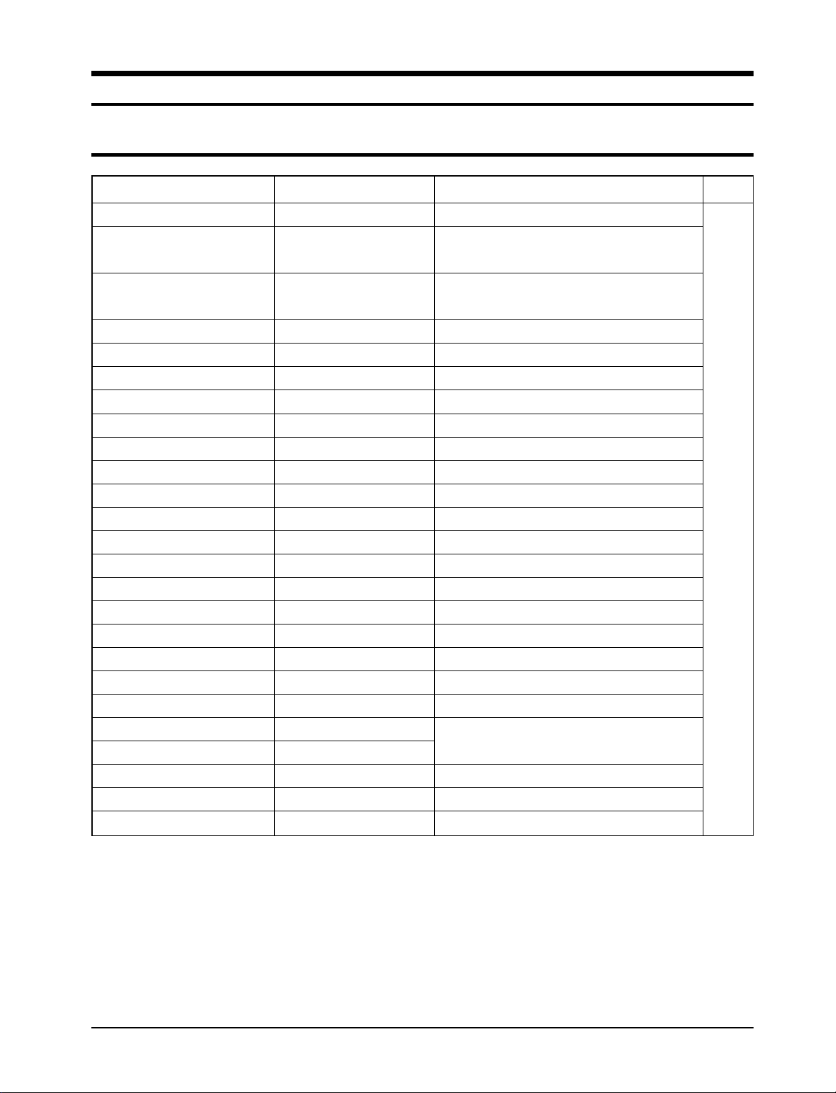
2. Product Specifications
2-1 Table
Item
T ype
Dimensions:
(Width X Height X Depth)
Packing Size
(Width X Height X Depth)
Voltage:
Phase
Frequency
Operating Current
Power Consumption
Refrigerant Type
Refrigerant Charge
Cooling Capacity
EER
Net Weight
Condenser
Condenser Fan
Evaporator
Evaporator Fan
Fan Motor
Compressor(Rotary)
Overload Protect
Compressor Capacitor
Fan Motor Capacitor
Fan Speed Control
Thermo Control
OFF Timer
Unit of Measure
-
mm
mm
Volt
-
Hz
A
W
FREON
g
BTU/h
BTU/h.W
kg
Row
Type
Row
Type
W
Model
µF/ VAC
µF/ VAC
-
-
hr
AWH126/127JE (COOL/HEAT)
Window
600
X 394 X 555
X 470 X 655
715
220 - 240
Single
50
5.9 / 5.3
1,350 / 1,210
R-22
680
11,500 / 11,500
8.5 / 9.5
45
X 14
2
Propeller Fan
2 X 14
Blower
AMAFS100ATEA
48H124JV1E4
MRA12030-12008
30 / 450
3.5 / 450
Fan speed switch (High & Low)
Thermistor
DUAL TYPE
24
Remarks
Samsung Electronics 2-1
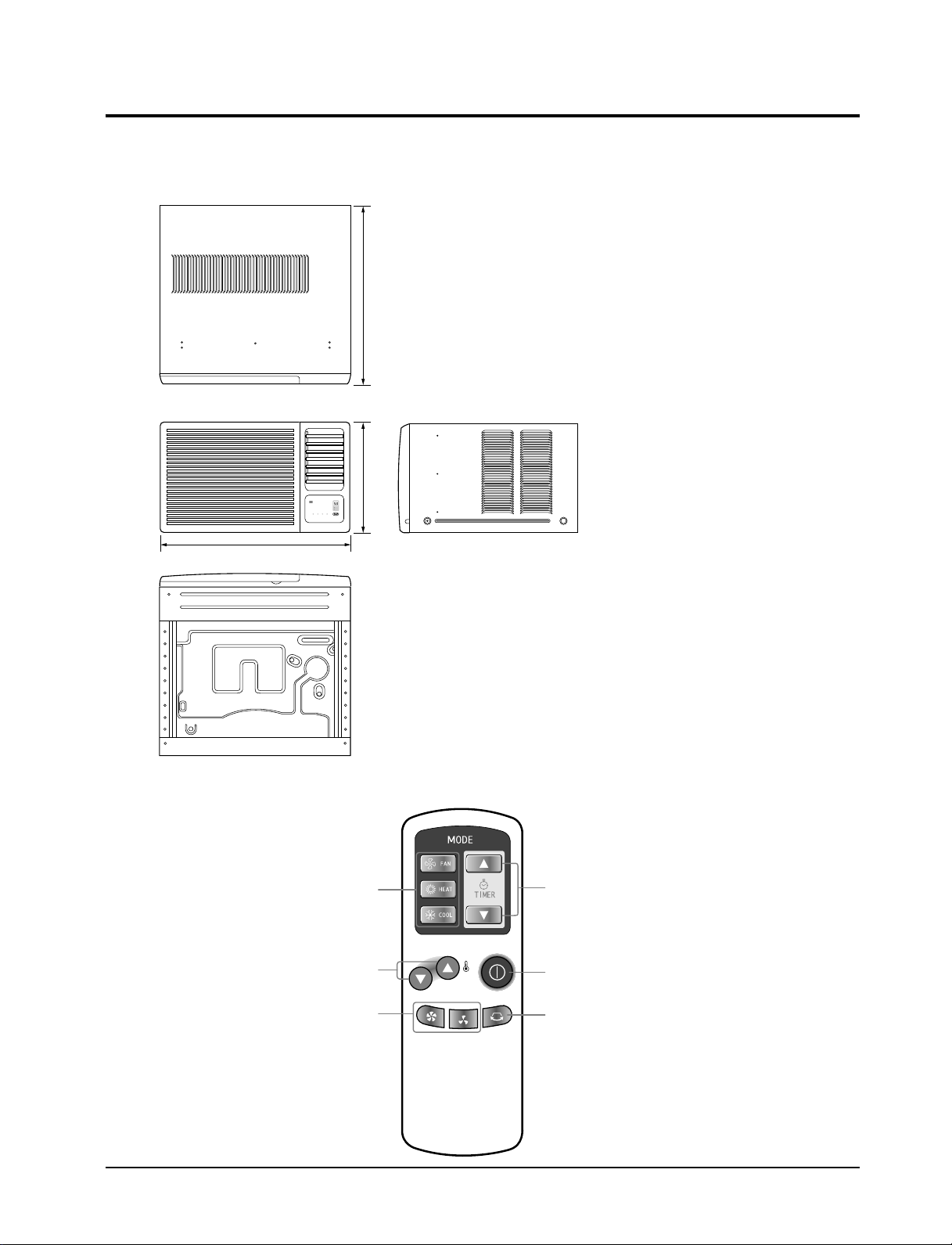
2-2 Dimensions
600
394 595
FANCOOLHEATDEICE
POWER / MODE
°C
Hour
2-2-1 Main Unit
Front view Side view
Unit : mm
2-2-2 Remote Control
Mode selection Buttons
(FAN, HEAT, COOL)
Temperature adjustment buttons
Fan speed adjustment Buttons
(HIGH, LOW)
2-2 Samsung Electronics
Timer setting buttons
ON/OFF Buttons
Air flow swing button

3. Installation and Operating Instructions
3-1 Installation
When selecting the area for installing the unit, be sure to obtain approval of the customer.
*
1. Make sure that you install the unit in an area that
provides good ventilation.
The air conditioner must not be blocked by any
obstacle affecting the air flow near the air inlet and
air outlet.
2. Make sure that you install the unit in an area which
can endure the weight and vibration of the unit.
3. Make sure that you install the unit away from heat
or vapor.
4. Make sure that you install the unit in an area where
the cooled air can be evenly spread in a room.
5. Make sure that you install the unit in an area away
from TVs, audio units, cordless phones, fluorescent
lighting fixtures and other electrical appliances.
(obtain a clearance of at least one meter)
Caution:
6. Make sure that you install the unit in an area which
provides easy drainage for condensed water.
7. Make sure that you install the unit in an area not
exposed to rain or direct sunlight.
(Install a separate sunblind if exposed to direct sun-
light.)
8. Do not install the unit in an area subjected to noise
or vibration amplification which may affect your
neighbor.
(Fix the unit firmly if mounted in a high place.)
Do not use the air conditioner in such areas as a greasy area(including machine oil),
saline area(sea side), or sulphuric area(hot spring). When using the air conditioner in these areas,
special maintenance is required. Contact your local dealer or our service center for advice.
Samsung Electronics 3-1

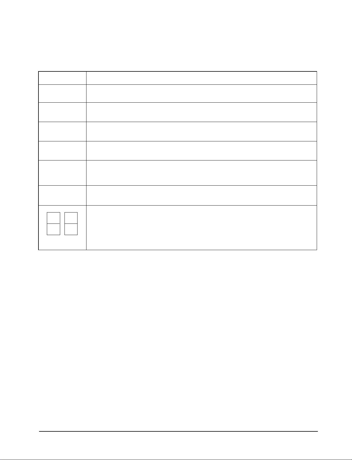
3-2 Function Description
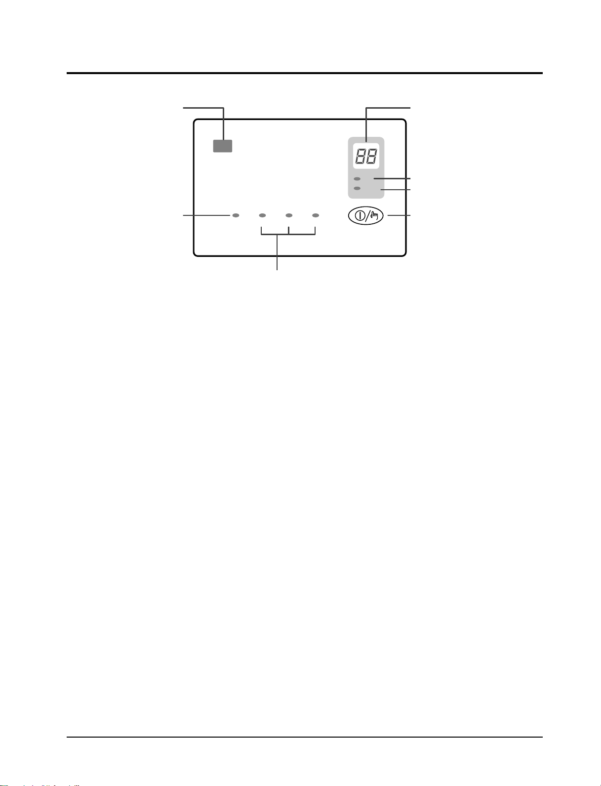
FANCOOLHEATDEICE
POWER / MODE
°C
Hour
Remote control sensor
Deice indicator
Operating mode indicator
Temperature/Timer settings
Temperature indicator
Timer indicator
POWER/MODE button
3-2-1 Cooling operation mode
The compressor is turned on and off according to the ambient temperature and set temperature.
1. Compressor on and off control
¥ Compressor on and off control according to the ambient temperature.
The compressor is turned off when "ambient temperature = set temperature -1ûC"
*
The compressor is turned on when "ambient temperature = set temperature +1ûC"
*
2. Default value after power reset →set temperature = 18ûC
FAN SPEED = HIGH
3. Set temperature indicating (setting) range : 1ûC interval from 18ûC to 30ûC.
3-2-2 Heating operation mode
The compressor is turned on and off according to the ambient temperature and set temperature.
1. Compressor on and off control.
¥ Compressor on and off control according to the ambient temperature.
The compressor is turned off when "ambient temperature = set temperature +1ûC"
*
The compressor is turned on when "ambient temperature = set temperature -1ûC"
*
2. Default value after power reset →set temperature = 24ûC
FAN SPEED = HIGH
3. Set temperature indicating (setting) range : 1ûC interval from 16ûC to 30ûC.
3-2-3 Fan operation mode
1. If "Fan operation mode" signal is received from remocon.
→ the compressor is immediately turned off and only fan motor is operated at set blowing speed.
→ it changes such as "HIGH → LOW → HIGH"( if Fan speed is selected).
2. The initial FAN speed is set to "HIGH".
3. The set temperature can not be indicated and set.
3-2 Samsung Electronics

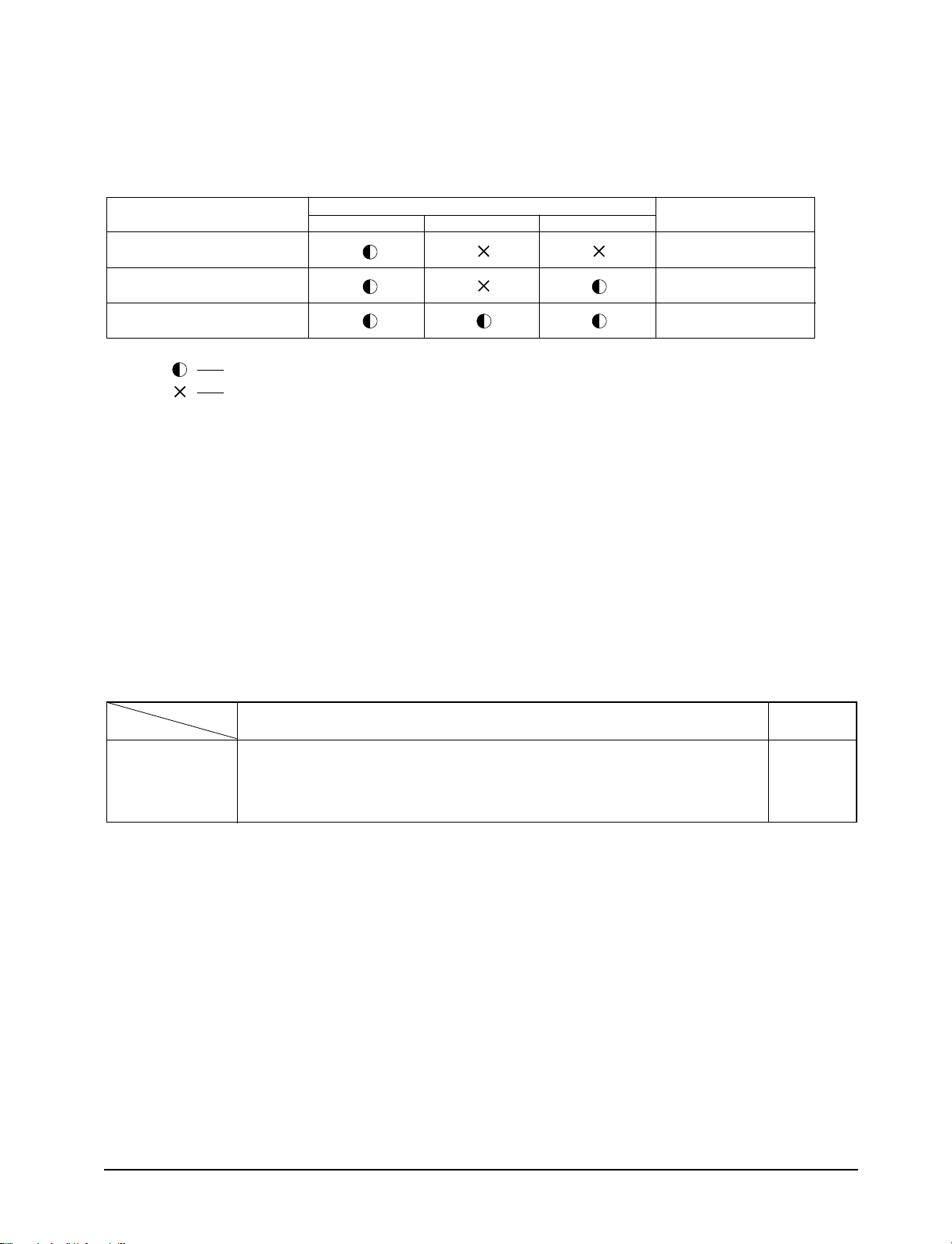
3-2-4 LED lamp and LED display indication in case of error detection
ERROR OPERATION
ROOM THERMISTOR
(OPEN OR SHORT)
INDOOR PIPE THERMISTOR
(OPEN OR SHORT)
OUTDOOR PIPE THERMISTOR
(OPEN OR SHORT)
LED LAMP DISPLAY
COOL HEAT FAN
7-SEG
LED DISPLAY
E1 displayed
E5 displayed
E6 displayed
Lamp blinking at every second (on for 0.5s and off for 0.5s)
LED lamp off
1. Set operation in case of error occurrence.
¥ Malfunction of each temperature sensor (open, short)
- Error mode display, warning sound.
- The operation status is off.
2. The "outdoor pipe thermistor" error mode carry out checking only during heating operation and
do not carry out checking during "COOLING" and "FAN" operation.
3-2-5 Panel key operation
Key discription
Key name
Power/Mode 1. Operation mode change and POWER OFF(in case of model option heat pump) TACT
at every ON
*
- Selected as "OFF –> COOL –> HEAT –> FAN –> OFF". (Default=OFF)
Continuous operation is not available.
*
Key operational function Key Type
Samsung Electronics 3-3
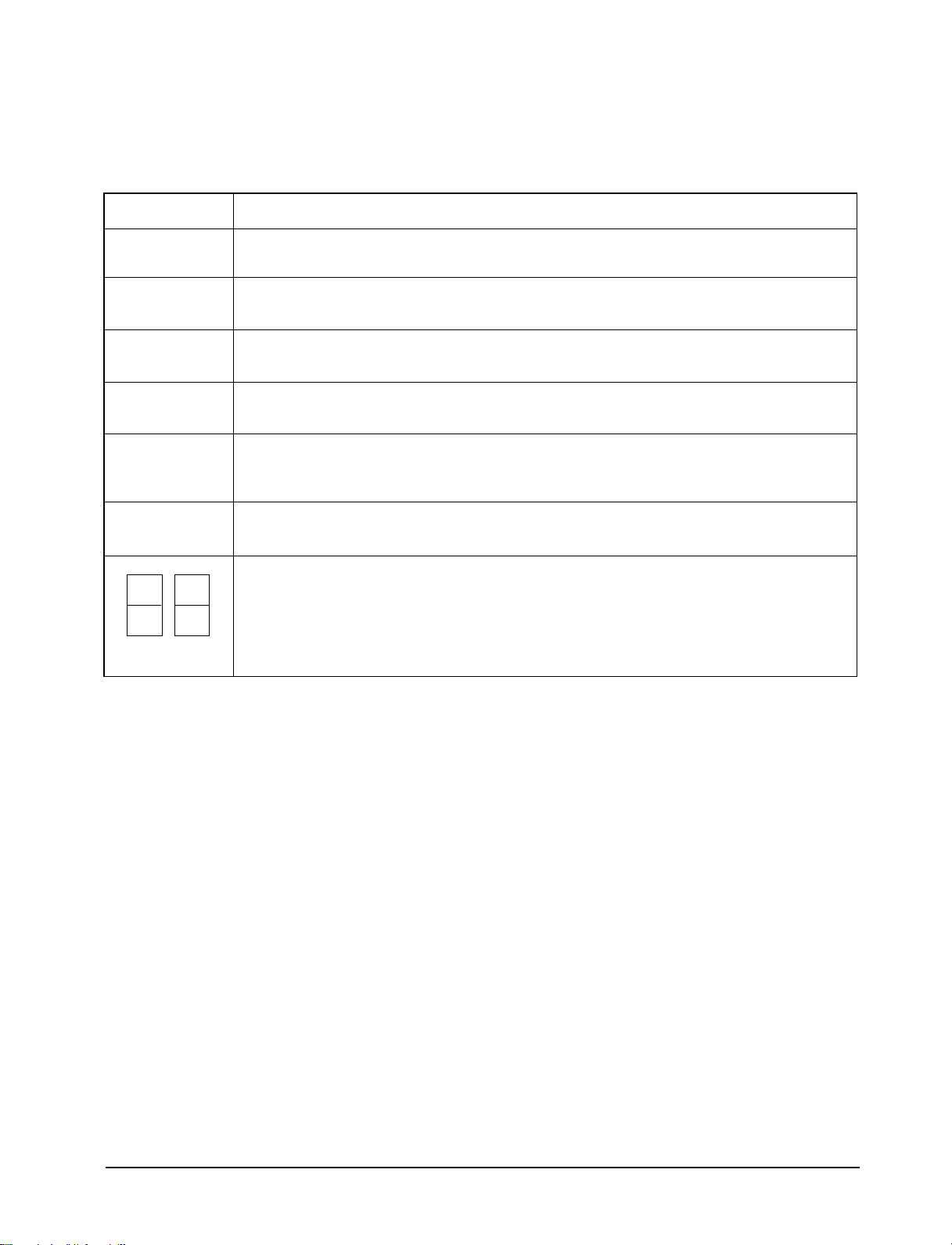
3-2-6 LED lamp operation specifications
LAMP name Operations specifications
COOL The mode is set to "COOL" –> ON
Others –> OFF
HEAT The mode is set to "HEAT" –> ON
Others –> OFF
FAN The mode is set to "FAN" –> ON
Others –> OFF
ûC The set temperature is displayed or set -> ON
Others –> OFF
HR During setting of the convenient reserve (OFF TIMER) time -> blinking
After setting of the convenient reserve (OFF TIMER) time -> ON
Others –> OFF
DEICE Till the "DEICING" operation is completed during heating opertion -> ON
Others –> OFF
In case of (set) temperature display
-> NO. (1) 7 seg. LED display indicates temperature of the tens digit (ûC, ûF)
-> NO. (2) 7 seg. LED display indicates temperature of the units digit (ûC, ûF)
In case of time (OFF TIMER) display
(1) (2)
-> NO. (1) 7 seg. LED display indicates time of the tens digit
-> NO. (2) 7 seg. LED display indicates time of the units digit
3-4 Samsung Electronics
3-2-7 Resistor values table of “ROOM THERMISTOR”, “INDOOR PIPE THERMISTOR”
and “OUTDOOR PIPE THERMISTOR” for each temperature
1. Room thermistor (SPEC : 103AT)
Temperature
[˚C]
70
69
68
67
66
65
64
63
62
61
60
59
58
57
56
55
54
53
52
51
50
49
48
47
46
45
44
43
42
41
40
39
38
37
36
35
34
33
32
31
30
THERMISTOR RESISTOR
[Kohm]
2.229
2.296
2.365
2.437
2.512
2.589
2.669
2.752
2.838
2.928
3.021
3.116
3.216
3.319
3.426
3.537
3.652
3.772
3.897
4.026
4.161
4.300
4.444
4.594
4.749
4.912
5.080
5.256
5.439
5.630
5.828
6.033
6.246
6.468
6.699
6.941
7.192
7.455
7.729
8.015
8.313
Temperature
[˚C]
29
28
27
26
25
24
23
22
21
20
19
18
17
16
15
14
13
12
11
10
9
8
7
6
5
4
3
2
1
0
-1
-2
-3
-4
-5
-6
-7
-8
-9
THERMISTOR RESISTOR
[Kohm]
8.622
8.944
9.281
9.632
10.000
10.380
10.780
11.200
11.630
12.090
12.560
13.060
13.570
14.120
14.680
15.280
15.900
16.550
17.240
17.960
18.700
19.480
20.290
21.150
22.050
22.990
23.900
25.030
26.130
27.280
28.470
29.720
31.040
32.430
33.890
35.430
37.050
38.760
40.560
Samsung Electronics
3-5
2. Indoor pipe Thermistor and Outdoor pipe Thermistor (SPEC : 10KD)
Temperature
[˚C]
70
69
68
67
66
65
64
63
62
61
60
59
58
57
56
55
54
53
52
51
50
49
48
47
46
45
44
43
42
41
40
39
38
37
36
35
34
33
32
31
30
THERMISTOR RESISTOR
[Kohm]
1.670
1.729
1.791
1.855
1.922
1.992
2.065
2.141
2.220
2.303
2.390
2.480
2.574
2.672
2.775
2.882
2.994
3.111
3.234
3.362
3.496
3.635
3.780
3.932
4.091
4.257
4.432
4.614
4.806
5.007
5.217
5.438
5.669
5.912
6.167
6.435
6.716
7.012
7.322
7.649
7.993
Temperature
[˚C]
29
28
27
26
25
24
23
22
21
20
19
18
17
16
15
14
13
12
11
10
9
8
7
6
5
4
3
2
1
0
-1
-2
-3
-4
-5
-6
-7
-8
-9
-10
THERMISTOR RESISTOR
[Kohm]
8.354
8.734
9.135
9.556
10.00
10.46
10.94
11.45
11.99
12.55
13.15
13.78
14.44
15.14
15.88
16.66
17.48
18.36
19.28
20.25
21.28
22.38
23.54
24.76
26.06
27.44
28.90
30.45
32.10
33.85
35.66
37.59
39.64
41.82
44.14
46.60
49.22
52.01
54.98
58.14
3-6
Samsung Electronics
3-2-8 About the safety devices
1. High temperature release : If temperature of the indoor pipe thermistor increases over the specified value during heating
operation, following operation is carried out for safety of the equipment.
A condition : temperature of indoor pipe thermistor is below 47ûC
B condition : temperature of indoor pipe thermistor is between 58ûC and 63ûC
C condition : temperature of indoor pipe thermistor is over 63ûC
1) High temperature release operation OFF condition = A condition
-> compressor ON (only in THERMO ON condition)
-> fan motor speed = set fan speed and cool blowing inhibiting operation
2) High temperature release operation ON condition = B condition
-> compressor ON
-> fan motor speed = HIGH operation if it was LOW
= HIGH operation if it was HIGH
3) High temperature release operation ON condition = C condition
-> fan motor speed = set fan speed
-> compressor OFF
2. Low temperature release : If temperature of the indoor pipe thermistor decreases below the specified value during cooling
operation, following operation is carried out for safety of the equipment.
A condition : temperature of indoor pipe thermistor is below -1ûC for more than 6 minutes
B condition : temperature of indoor pipe thermistor is over 5ûC
1) Low temperature release ON condition = A condition
-> compressor OFF
-> fan motor "set fan speed"
2) Low temperature release OFF condition = B condition
-> The compressor is turned on if ON condition is satisfied after comparing the ambient temperature with the set
temperature
-> fan motor "set fan speed"
[Detailed description]
1) If temperature of indoor pipe thermistor is below -1ûC for more than 6 minutes, the fan motor continues to operate at
the set fan speed and the compressor is turned off(Low temperature release operation)
2) If temperature of the indoor pipe thermistor increases over +5ûC during low temperature release operation, normal
operation is recovered
: compressor ON, fan mtor set fan speed -> Low temperature release operation OFF
3) If temperature of indoor pipe thermistor increases over 0ûC during counting 6 minutes below -1ûC, the counter is reset.
Samsung Electronics 3-7
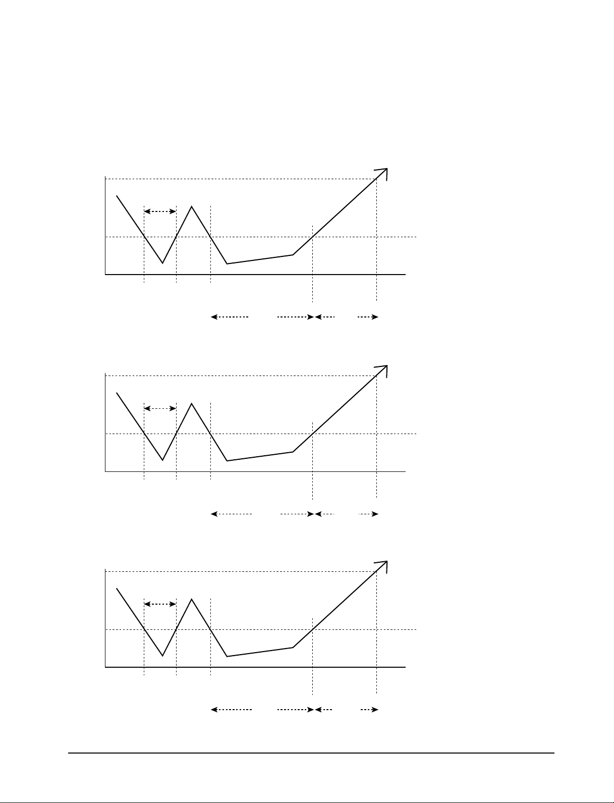
3. Deicing operation : If temperature of the outdoor pipe thermistor decreases below the specified value during heating operation, following operation is carried out for safety of the equipment.
Outdoor pipe
Thermistor
temperature (A-Condition) : STANDARD
12[ûC]
100min below
-4[ûC]
100min
COUNT
ON
Outdoor pipe
Thermistor
temperature (B-Condition) : STANDARD
12[ûC]
-6[ûC]
30min
COUNT
ON
Outdoor pipe
Thermistor
temperature (C-Condition) : STANDARD
12[ûC]
100min
COUNT
OFF
30min below
30min
COUNT
OFF
100min
COUNT
ON
30min
COUNT
ON
Deicing
operation
100min
ON
5min
Deicing
operation
ON
30min 5min
Deicing
operation
OFF
Deicing
operation
OFF
10min below
-8[ûC]
10min
COUNT
ON
10min
COUNT
OFF
10min
COUNT
ON
Deicing
operation
ON
2min 5min
Deicing
operation
OFF
3-8 Samsung Electronics
1) Deicing detecting condition
¥ If one of A, B and C conditions is satisfied, deicing operation is carried out.(AUBUC)
¥ If counting time is overlapped due to detection reference temperature change during counting of the deicing con-
dition, deicing operation starts when the counting time is finished first.
¥ The maximum counting time is 100 minutes.
- During deicing operation, the left and right swing motor is turned off and stops at the position before swing.
- If operation is turned off during deicing operation, it is finished and the compressor is turned off.
-> Deice lamp ON, fan motor OFF.
2) Display indication.
¥ The deice lamp is turned on additionally during deicing cycle.
¥ Only the deice lamp is turned off when deicing is finished.
3) In case of turning off during deicing operation.
¥ The compressor is turned off after finishing the deicing operation.
¥ The deice lamp is turned on during deicing cycle and is turned off when deicing is finished.
4) In case of changing mode to cooling operation during deicing operation.
¥ Cooling operation is carried out after carrying out deicing operation.
¥ After the compressor is turned off and 1 minutes is passed, it is restarted.
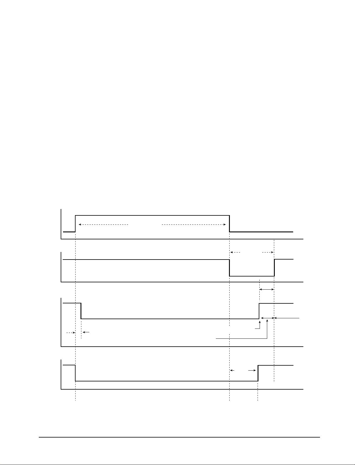
5) Load operation during deicing operation.
ÒDEICEÓ LED ON
CYCLE
COMPRESSOR
FAN
MOTOR
4-WAY
VALVE
ON
1sec
ON
DEICE TIME
OFF
COOL BLOWING INHIBITION
OFF
ÒDEICEÓ LED OFF
1min
OFF
THERMO ON
55sec
2sec
ON
SET FAN SPEED
AND COOL
BLOWING
INHIBITION
Samsung Electronics 3-9
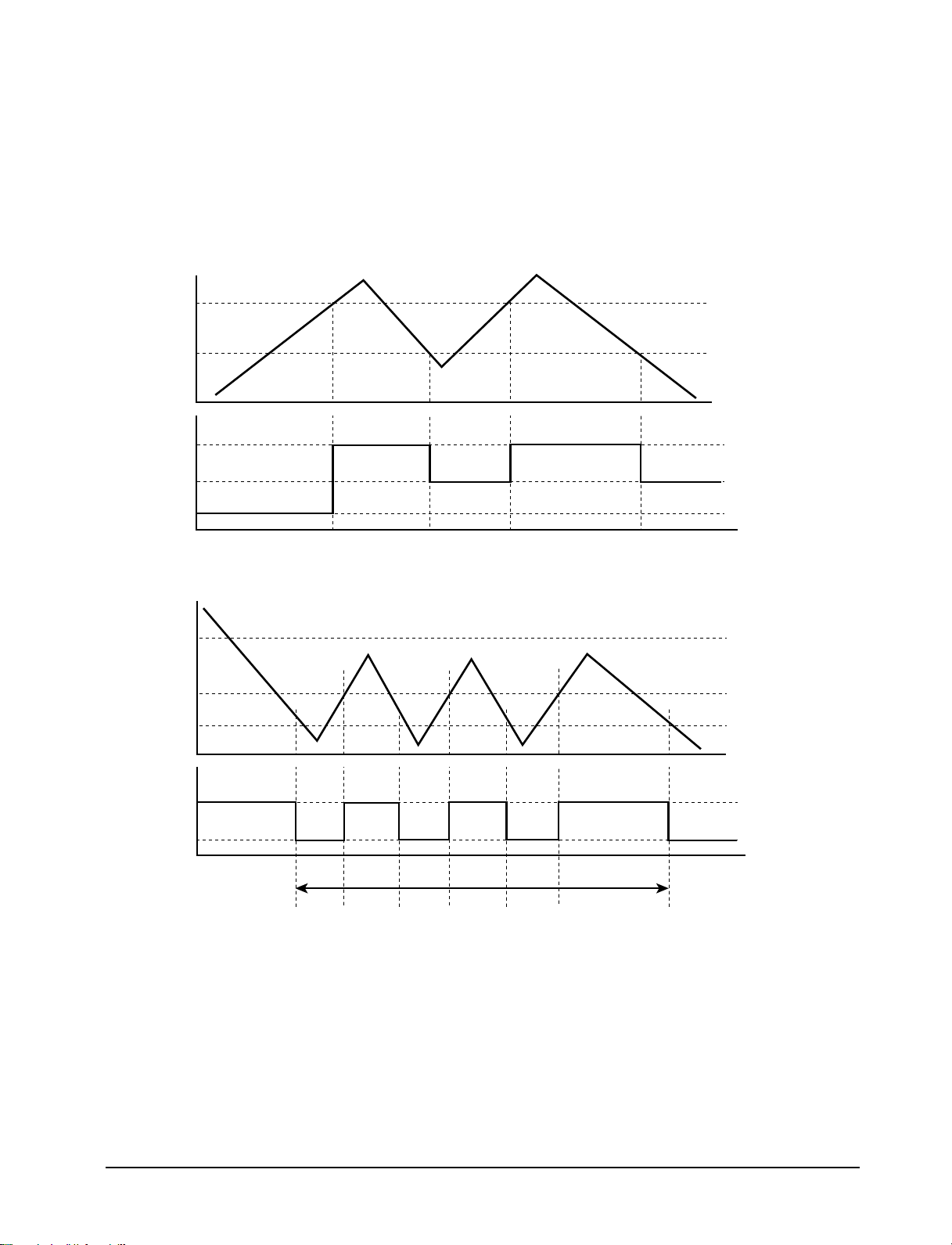
4. Cool blowing inhibiting control : In order to inhibit cool blowing during heating operation, the fan motor is operated when
temperature of the indoor pipe thermistor is above the specified value.
¥ The fan motor speed is controlled according to the temperature of condition of the indoor pipe thermistor.
< Compressor OFF -> Compressor ON >
Indoor pipe
thermistor
32[ûC]
30[ûC]
FAN MOTOR
CONTROL
SET FAN SPEED
LOW FAN
OFF
< Compressor ON -> Compressor OFF >
Indoor pipe
thermistor
32[ûC]
31[ûC]
30[ûC]
FAN MOTOR
CONTROL
LOW FAN
OFF
30sec
1) When the indoor pipe thermistor temperature is increasing
indoor pipe thermistor temperature = below 32ûC --> fan motor OFF
indoor pipe thermistor temperature = over 32ûC --> fan motor speed "set blower speed"
2) When the indoor pipe thermistor temperature is decreasing
indoor pipe thermistor temperature = over 30ûC --> fan motor speed "set blower speed"
indoor pipe thermistor temperature = below 30ûC --> fan motor speed "Low"
3) But if the compressor is operating, the fan motor is not turned off but is operated weakly even if the indoor pipe ther-
mistor temperature decreases.
3-10 Samsung Electronics

< Compressor ON -> Compressor OFF >
indoor pipe thermistor temperature = below 30ûC --> fan motor speed "Low"
indoor pipe thermistor temperature = over 30ûC --> fan motor OFF
30s is passed after compressor is turned off --> fan motor OFF
3-2-9 Compressor delayed operation and 4-way valve delayed operation :
The compressor is turned on after 3 minutes from power resetting or compressor turning off during cooling
or heating operation.
1) The compressor can be turned on after "3 minutes delay" from power resetting or compressor turning off.
2) The 4 way valve is turned off/on after "2 minutes and 55 seconds delay" in the on/off condition.
(during heating operation)
3) The operation is stopped after "2 minutes and 55 seconds delay" in the off condition when the 4 way valve is
turned on.
Samsung Electronics 3-11
3. Installation and Operating Instructions
3-1 Installation
When selecting the area for installing the unit, be sure to obtain approval of the customer.
*
1. Make sure that you install the unit in an area that
provides good ventilation.
The air conditioner must not be blocked by any
obstacle affecting the air flow near the air inlet and
air outlet.
2. Make sure that you install the unit in an area which
can endure the weight and vibration of the unit.
3. Make sure that you install the unit away from heat
or vapor.
4. Make sure that you install the unit in an area where
the cooled air can be evenly spread in a room.
5. Make sure that you install the unit in an area away
from TVs, audio units, cordless phones, fluorescent
lighting fixtures and other electrical appliances.
(obtain a clearance of at least one meter)
Caution:
6. Make sure that you install the unit in an area which
provides easy drainage for condensed water.
7. Make sure that you install the unit in an area not
exposed to rain or direct sunlight.
(Install a separate sunblind if exposed to direct sun-
light.)
8. Do not install the unit in an area subjected to noise
or vibration amplification which may affect your
neighbor.
(Fix the unit firmly if mounted in a high place.)
Do not use the air conditioner in such areas as a greasy area(including machine oil),
saline area(sea side), or sulphuric area(hot spring). When using the air conditioner in these areas,
special maintenance is required. Contact your local dealer or our service center for advice.
Samsung Electronics 3-1
3-2 Function Description
FANCOOLHEATDEICE
POWER / MODE
°C
Hour
Remote control sensor
Deice indicator
Operating mode indicator
Temperature/Timer settings
Temperature indicator
Timer indicator
POWER/MODE button
3-2-1 Cooling operation mode
The compressor is turned on and off according to the ambient temperature and set temperature.
1. Compressor on and off control
¥ Compressor on and off control according to the ambient temperature.
The compressor is turned off when "ambient temperature = set temperature -1ûC"
*
The compressor is turned on when "ambient temperature = set temperature +1ûC"
*
2. Default value after power reset →set temperature = 18ûC
FAN SPEED = HIGH
3. Set temperature indicating (setting) range : 1ûC interval from 18ûC to 30ûC.
3-2-2 Heating operation mode
The compressor is turned on and off according to the ambient temperature and set temperature.
1. Compressor on and off control.
¥ Compressor on and off control according to the ambient temperature.
The compressor is turned off when "ambient temperature = set temperature +1ûC"
*
The compressor is turned on when "ambient temperature = set temperature -1ûC"
*
2. Default value after power reset →set temperature = 24ûC
FAN SPEED = HIGH
3. Set temperature indicating (setting) range : 1ûC interval from 16ûC to 30ûC.
3-2-3 Fan operation mode
1. If "Fan operation mode" signal is received from remocon.
→ the compressor is immediately turned off and only fan motor is operated at set blowing speed.
→ it changes such as "HIGH → LOW → HIGH"( if Fan speed is selected).
2. The initial FAN speed is set to "HIGH".
3. The set temperature can not be indicated and set.
3-2 Samsung Electronics
3-2-4 LED lamp and LED display indication in case of error detection
ERROR OPERATION
ROOM THERMISTOR
(OPEN OR SHORT)
INDOOR PIPE THERMISTOR
(OPEN OR SHORT)
OUTDOOR PIPE THERMISTOR
(OPEN OR SHORT)
LED LAMP DISPLAY
COOL HEAT FAN
7-SEG
LED DISPLAY
E1 displayed
E5 displayed
E6 displayed
Lamp blinking at every second (on for 0.5s and off for 0.5s)
LED lamp off
1. Set operation in case of error occurrence.
¥ Malfunction of each temperature sensor (open, short)
- Error mode display, warning sound.
- The operation status is off.
2. The "outdoor pipe thermistor" error mode carry out checking only during heating operation and
do not carry out checking during "COOLING" and "FAN" operation.
3-2-5 Panel key operation
Key discription
Key name
Power/Mode 1. Operation mode change and POWER OFF(in case of model option heat pump) TACT
at every ON
*
- Selected as "OFF –> COOL –> HEAT –> FAN –> OFF". (Default=OFF)
Continuous operation is not available.
*
Key operational function Key Type
Samsung Electronics 3-3
3-2-6 LED lamp operation specifications
LAMP name Operations specifications
COOL The mode is set to "COOL" –> ON
Others –> OFF
HEAT The mode is set to "HEAT" –> ON
Others –> OFF
FAN The mode is set to "FAN" –> ON
Others –> OFF
ûC The set temperature is displayed or set -> ON
Others –> OFF
HR During setting of the convenient reserve (OFF TIMER) time -> blinking
After setting of the convenient reserve (OFF TIMER) time -> ON
Others –> OFF
DEICE Till the "DEICING" operation is completed during heating opertion -> ON
Others –> OFF
In case of (set) temperature display
-> NO. (1) 7 seg. LED display indicates temperature of the tens digit (ûC, ûF)
-> NO. (2) 7 seg. LED display indicates temperature of the units digit (ûC, ûF)
In case of time (OFF TIMER) display
(1) (2)
-> NO. (1) 7 seg. LED display indicates time of the tens digit
-> NO. (2) 7 seg. LED display indicates time of the units digit
3-4 Samsung Electronics
 Loading...