

Samsung AW0700B, AW07F0SAB, AW07F1SBA, AW07F2SBA, AW07F1SDA Service Manual
...
SERVICE
Manual
ROOM AIR CONDITIONER
AW0700B
AW07F0SAB
AW07F(A)1SBA
AW07F(A)2SBA
AW07F(A)1SDA
AW07F(A)2SDA
AW07F(A)0SEA
AW07F(A)1SEA
AW07F(A)2SEA
AW0800A
AW08F0SAA
AW09F(A)1SBA
AW09F(A)2SBA
AW09F(A)2SBC
AW09F(A)1SDA
AW09F(A)2SDA
AW09F(A)0SEA
AW09F(A)1SEA
AW09F(A)2SEA
AW09F0SAA
AW12F(A)0JCA
AW12F(A)1JBA
AW12F(A)2JB(C)A
AW12F(A)1JDA
AW12F(A)2JDA
AW12F(A)1JEA
AW12F(A)2JEA
AW1000A
AW10F0JAA
AW12F1JAA
AW1200A
AW1210A
AW12F0MAA
AW1400A
AW14F(A)1MB(C)A
AW14F(A)2MBA
AWT18F(A)1MDA
AW18F(A)1MEA
AW18F(A)2MEA
AW1800A
AW18F(A)2MBA
AW2410C
AWT24F(A)1MEA
AW24F(A)0MCA
AW24F(A)1MBA
AW24F(A)1MBC
AW24F(A)2MBB
AW18F(A)1MEB
AW18F1MBD
AW18F2MBD
CONTENTSAIR CONDITIONER
1. Precautions
2. Product Specifications
3. Installation and Operating
Instructions
4. Disassembly and Reassembly
5. Troubleshooting
6. Exploded Views and Parts List
7. Block Diagram
8. Wiring Diagram
6
1. Precautions
1. Precautions
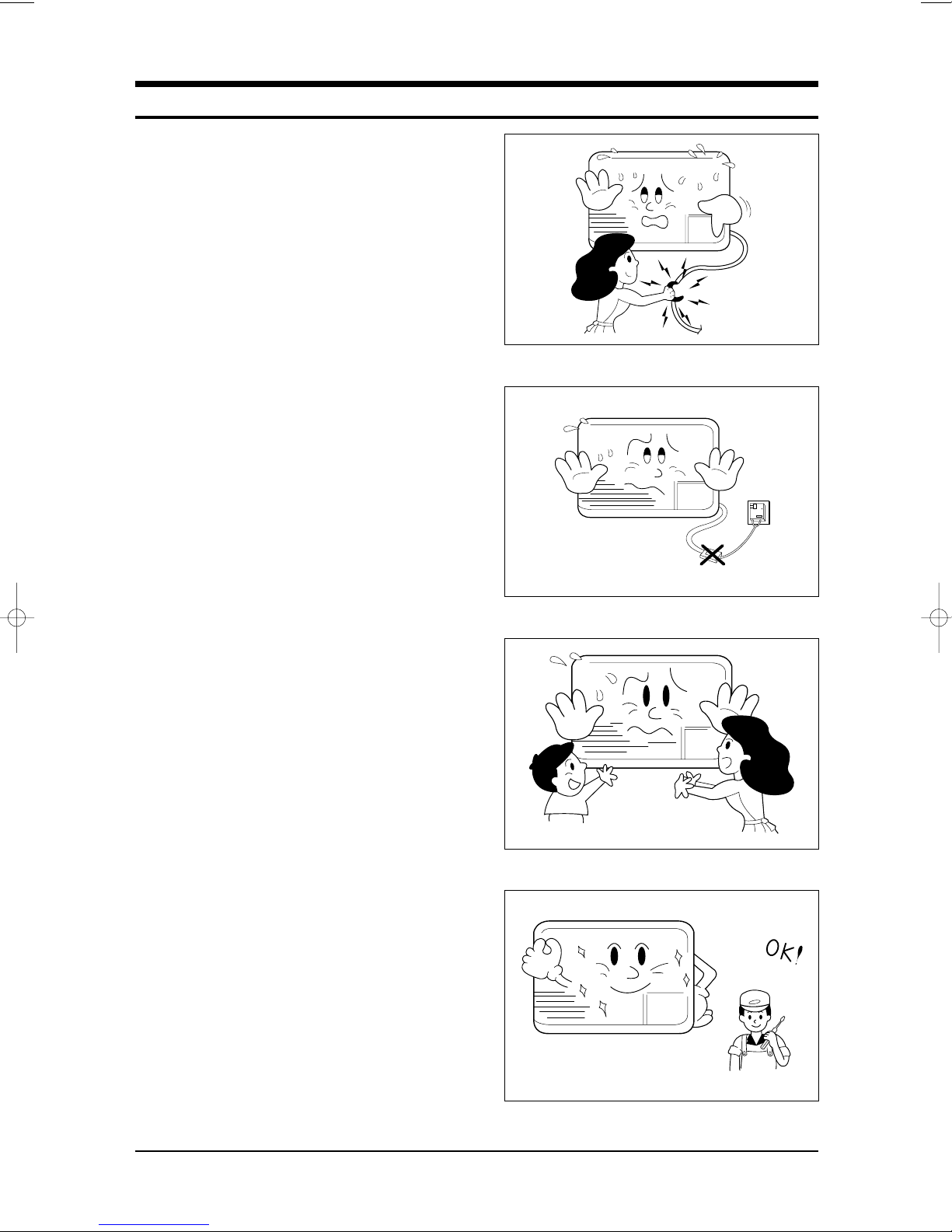
1. Warning: Prior to repair, disconnect the
power cord from the circuit breaker.
2. Use proper parts: Use only exact
replacement parts. (Also, we recommend
replacing parts rather than repairing them.)
3. Use the proper tools: Use the proper tools
and test equipment, and know how to use
equipment may cause problems laterintermittent contact, for example.
4. Power Cord: Prior to repair, check the
power cord and replace it if necessary.
5. Avoid using an extension cord, and avoid
tapping into a power cord. This practice
may result in malfunction or fire.
6. After completing repairs and reassembly,
check the insulation resistance.
Procedure: Prior to applying power, measure
the resistance between the power cord and the
ground terminal. The resistance must be
greater than 30 megaohms.
Fig. 1-1 Avoid Dangerous Contact
7. Make sure that the grounds are adequate.
8. Make sure that the installation conditions
are satisfactory.
Relocate the unit if necessary.
9. Keep children away from the unit while it is
being repaired.
10. Be sure to clean the unit and its surrounding
area.
Fig. 1-2 No Tapping and No Extension Cords
Fig. 1-3 No Kids Nearby!
Samsung Electronics 1-1
Fig. 1-4 Clean the Unit
Notice
: The symbol of model name
Type Model Name
AW0700B
AW07F0SAB
A
B
C
AW07F(A)1SBA
AW07F(A)2SBA
AW07F(A)1SDA
AW12F(A)0JCA
AW12F(A)1JBA
AW12F(A)2JB(C)A
AW1200A
AW1210A
AW12F0MAA
AW14F(A)1MB(C)A
AW14F(A)2MBA
AW07F(A)2SDA
AW07F(A)0SEA
AW07F(A)1SEA
AW07F(A)2SEA
AW0800A
AW12F(A)1JDA
AW12F(A)2JDA
AW12F(A)1JEA
AWT18F(A)1MDA
AW18F(A)1MEA
AW18F(A)2MEA
AW1800A
AW18F(A)2MBA
AW08F0SAA
AW09F(A)1SBA
AW09F(A)2SBA
AW09(F(A)2SBC
AW09F(A)1SDA
AW12F(A)2JEA
AW1000A
AW10F0JAA
AWT24F(A)1MEA
AW24F(A)0MCA
AW24F(A)1MBA
AW24F(A)1MBC
AW24F(A)2MBB
AW09F(A)2SDA
AW09F(A)0SEA
AW09F(A)1SEA
AW09F(A)2SEA
AW09F0SAA
AW12F1JAA
AW18F(A)1MEB
AW18F1MBD
AW18F2MBD
1-2 Samsung Electronics
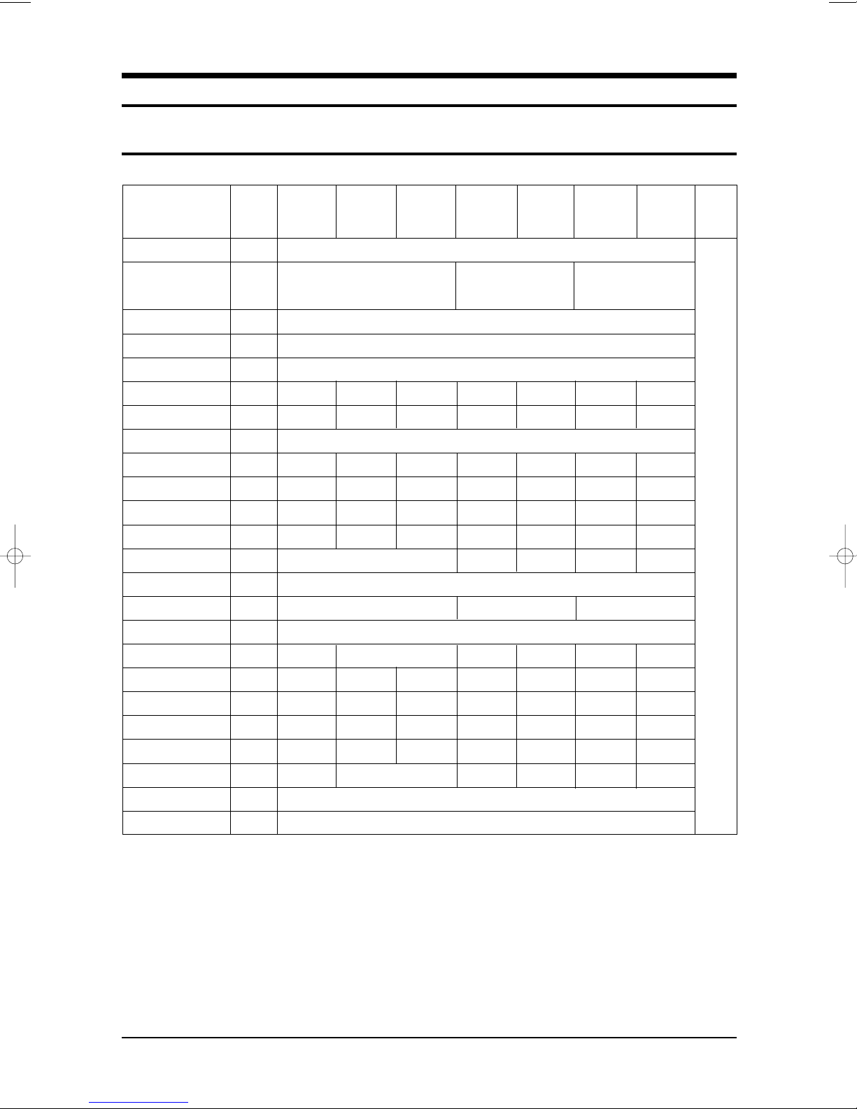
2. Product Specifications
2-1 Table
Item
Type
Dimension:
(Width x Height x Depth)
Voltage
Phase
Frequency
Operation Current
Power Consumption
Refrigerant Type
Refrigerant Charge
Capacity
EER
Net Weight
Condenser
Condenser Fan
Evaporator
Evaporator Fan
Fan Motor
Compressor (Rotary)
Overload Protect
Compressor Capacitor
Fan Motor Capacitor
Fan Speed
Thermo Control
Air Swing
Unit of
Measure
FREON
BTU/h.W
MODEL
MODEL
µF/VAC
µF/VAC
MODEL
-
mm
Volt
-
Hz
A
W
g
BTU/h
kg
Row
Type
Row
Type
-
RPM
-
AW0700B
AW07F0SAB
6.8
715
350
7000
9.8
28
IC-9630SWD6C
44A072HW1EB
MRA98706-12008
25/370
6/450
800/750/700
AW0800A
AW08F0SAA
520 x 345 x 485
7.4
815
380
8000
9.8
2 x 15
2 x 14
44A080HU1EB
MRA12083-12008
35/370
6/450
AW09F0SAA
9.1
1000
420
9000
9
29
IC-9630SWD6E
910/810/750
29
44B092HW1EF
MRA12093-12007
45/400
6/450
AW1000A
AW1010A
AW12F1JAA
AW10F0JAA
WINDOW
600 x 394 x 595
115
SINGLE
60
9.2
1020
R-22
485
10000
9.8
45
2 x 17
Propeller Fan
Blower
AFS095ZREA
44B102HU1EF
MRA12109-12007
40/370
8/440
920/820/770
THERMOSTAT
NO or M2CK59ZT79-H
1300
610
12300
3 x 17
2 x 14
AFS100ZREB
44B124HU1EL
MRA98693-12008
45/370
15/450
920/850/780
12
9.4
45
OSME-708SWC
44B124HU1EL
800/750/700
AW1200A
AW1210A
AW1400A
AW12F0MAA
660 x 425 x 730
11.7
1275
580
12500
9.8
50
2 x 19
MRA98693-12007
45/370
8/450
12.0
1400
700
1400
10.0
3 x 19
2 x 15
OSME-806SWC
44B135HX1EL
MRA98693-12007
50/370
8/450
950/850/750
Remarks
61
Samsung Electronics 2-1
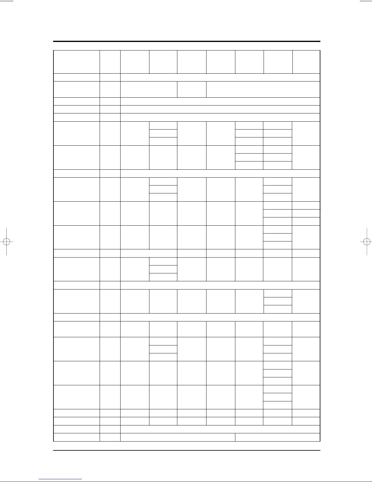
Table (cont.)
Item
Type
Dimension:
(Width x Height x Depth)
Voltage
Phase
Frequency
Operation Current
Power Consumption
Refrigerant Type
Refrigerant Charge
Capacity
EER
Net Weight
Condenser
Condenser Fan
Evaporator
Evaporator Fan
Fan Motor
Compressor (Rotary)
Overload Protect
Compressor Capacitor
Fan Motor Capacitor
Fan Speed
Thermo Control
Air Swing
Measure
BTU/h.W
Unit of
-
mm
Volt
-
Hz
A
W
FREON
g
BTU/h
kg
Row
Type
Row
Type
MODEL
MODEL
-
µF/VAC
µF/VAC
RPM
-
MODEL
AW07F(A)1SBA
AW07F(A)2SBA
520 x 345 x 485
3.5
750
410
7000
9.3
2 x 15
IC-9630SWF6G
44A072IW1EB
MRA12043-12008
25/370
3/450
910/780/690
AW09F(A)1SBA
AW09F(A)2SBA
AW09F(A)2SBC
29
IC-9630SWF6G
44B092IW1EF
44B092IW1EF
44B092IU1EF
MRA12032-12008
910/780/690
AW12F(A)0JCA
AW12F(A)1JBA
AW12F(A)2JB(C)A
600 x 394 x 595
4.7
4.7
4.5
1000
420
420
525
9000
9
2 x 15
2 x 15
3 x 15
2 x 14
20/370
3/450
NO or M2LJ49ZV32
6
1290
510
12000
9.3
45
2 x 17
AFS105ZUEA
44B124HU1EL
MRA12008-12008
30/450
3.5/450
900/840/780
AW14F(A)1MB(C)A
AW14F(A)2MBA
WINDOW
220 (230-208)
SINGLE
60
6.5
1400
R-22
570
14000
10
53
2 x 19
Propeller Fan
2 x 15
Blower
OSME-906SWC
44B135IU1EL
MRA12074-12007
30/450
6/450
950/850/750
THERMOSTAT
AW1800A
AW18F(A)2MBA
9.1
9.5
1860
2000
1090
18000
9.7
61
3 x 16
3 x 15
AFS145ZUEA
YSK160-6A
48B175IV1EH
MRA12107-12007
35/450
6/450
1060/1010/970
AW24F(A)0MCA
AW24F(A)1MBA
AW24F(A)2MBB
600 x 425 x 730
12.5
12.5
11
2790
2790
2500
1320
1320
1280
24000
24000
20500
8.5
8.5
8.2
71
3 x 16
4 x 15
4 x 15
3 x 15
AFS145ZUEA
EDB260211A
EDB260211A
48B220IV1EH
INTERNAL
INTERNAL
MRA12068-12007
30/450
30/450
40/450
6/450
1060/1010/970
NO or M2LJ49ZU32
AW2410C/XAA
AW24F(A)1MBC
12.1
2700
1140
23700
24000
8.8
64
3 x 19
4 x 15
YSK160-6A
AFS145ZUEA
55A240IU2EN
INTERNAL
40/450
6/450
1030/980/930
2-2 Samsung Electronics
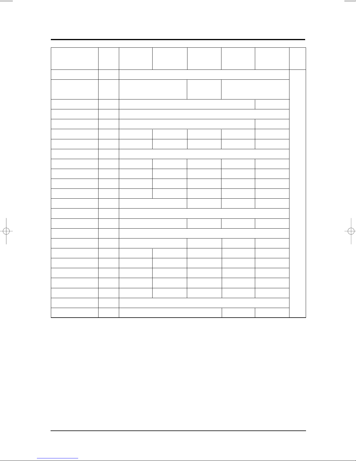
Table (cont.)
Item
Type
Dimension:
(Width x Height x Depth)
Voltage
Phase
Frequency
Operation Current
Power Consumption
Refrigerant Type
Refrigerant Charge
Capacity
EER
Net Weight
Condenser
Condenser Fan
Evaporator
Evaporator Fan
Fan Motor
Compressor (Rotary)
Overload Protect
Compressor Capacitor
Fan Motor Capacitor
Fan Speed
Thermo Control
Air Swing
Measure
BTU/h.W
Unit of
-
mm
Volt
-
Hz
A
W
FREON
g
BTU/h
kg
Row
Type
Row
Type
MODEL
MODEL
µF/VAC
µF/VAC
RPM
MODEL
AW07F(A)1SDA
AW07F(A)2SDA
520 x 345 x 485
3.7
740
410
7000
9.5
28
2 x 15
2 x 14
IC-9430SWJ5A
44A070MW1EB
MST24AMN-12008
20/400
3/450
910/860/810
AW09F(A)1SDA
AW09F(A)2SDA
200-220
50
4.7
1000
360
9000
9.0
29
44B092MW1EF
MRA12054-12008
30/450
3/450
910/860/810
M2LJ49ZV32
AW12F(A)1JDA
AW12F(A)2JDA
WINDOW
600 x 394 x 595
200-220
SINGLE
6.8
1330
R-22
660
12000
9.0
45
2 x 14
Propeller Fan
2 x 14
Blower
AFS105AUEA
48A124MV1EL
MRA98706-12008
30/450
4/450
890/840/780
THERMOSTAT
AWT18F(A)1MDA
660 x 425 x 730
660 x 425 x 730
10.5
2050
1480
18000
8.8
71
4 x 16
3 x 15
OSME-1206SWC
48B180MT1EH
MRA12108-12007
40/450
6/450
930/880/830
M2LJ49ZU32
AW18F1MBD
AW18F2MBD
660 x 425 x 730
220
60
8.0
1800
1150
18000
10.0
61
3 x 15
3 x 16
YSK160-6A
48D180IU1EQ
MRA12046-12007
35/450
6/450
1000/910/850
M2LJ49ZU39
Remarks
Samsung Electronics 2-3
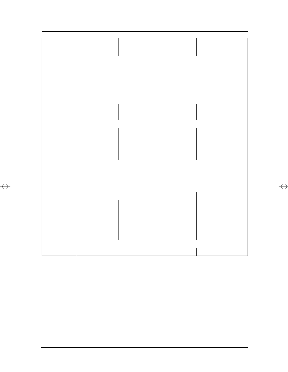
Table (cont.)
Item
Type
Dimension:
(Width x Height x Depth)
Voltage
Phase
Frequency
Operation Current
Power Consumption
Refrigerant Type
Refrigerant Charge
Capacity
EER
Net Weight
Condenser
Condenser Fan
Evaporator
Evaporator Fan
Fan Motor
Compressor (Rotary)
Overload Protect
Compressor Capacitor
Fan Motor Capacitor
Fan Speed
Thermo Control
Air Swing
Unit of
Measure
FREON
BTU/h
BTU/h.W
Row
Type
Row
Type
MODEL
MODEL
µF/VAC
µF/VAC
RPM
MODEL
AW07F(A)0SEA
AW07F(A)1SEA
AW07F(A)2SEA
-
mm
Volt
-
Hz
A
W
g
kg
44A070JW1EB
-
MST24AMN-12008
850/810/750
-
520 x 345 x 485
3.5
750
410
7000
9.3
28
2 x 15
2 x 14
IC-9430SWJ5A
25/450
2.5/450
AW09F(A)0SEA
AW09F(A)1SEA
AW09F(A)2SEA
600 x 394 x 595
4.5
1000
390
9000
9.0
29
44B092JW1EF
MRA12056-12007
30/450
3/450
910/860/810
NO or M2LJ49ZV32
MRA12030-12008
AW12F(A)1JEA
AW12F(A)2JEA
WINDOW
220-240
SINGLE
50
5.8
1330
R-22
660
12000
9.0
45
2 x 14
Propeller Fan
2 x 14
Blower
AFS105AUEA
48A124JV1EL
30/450
3.5/450
890/840/780
THERMOSTAT
AW18F(A)1MEA
AW18F(A)2MEA
9
2000
1160
18000
9.0
60
OSME-1404SAC
48B180JV1EH
MRA12016-12007
40/450
6/450
1060/1010/960
AWT24F(A)1MEA AW18F(A)1MEB
660 x 425 x 730
3 x 16
OSME-1256SWC
AWG5532EXC
14
3000
980
24000
8.0
71
INTERNAL
45/450
6/450
930/880/830
M2LJ49ZU32
9.0
1950
785
18000
8.5
55
3 x 19
3 x 15
OSME-1404SAC
48B1180JV2EH
MRA12147-12007
35/450
6/450
1030/980/1930
2-4 Samsung Electronics
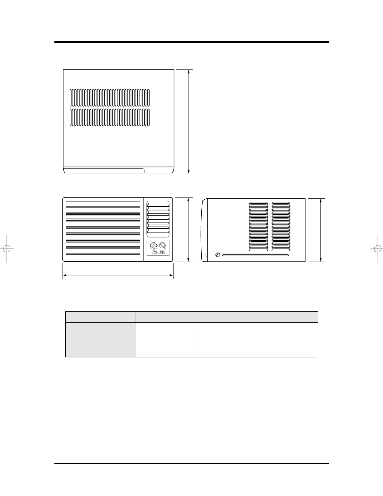
2-2 Dimensions
W
HH
D
2-2-1 Main Unit
(Unit : mm)
Front view
Type W H D
A 520 345 485
B 600 394 595
C 660 425 730
Side view
Samsung Electronics 2-5

MEMO
2-6 Samsung Electronics
3. Installation and Operating Instructions
3-1 Installation
3-1-1 Selecting Area for Installation
1. Make sure that you install the unit in an area
providing good ventilation. The air conditioner
must not be blocked by any obstacle affecting the
air flow near the air inlet and air outlet.
2. Make sure that you install the unit in an area that
allow good air handling. The installation area
must be able to endure vibration from the unit.
3. Make sure that you install the unit away from
heat or vapor.
4. Make sure that you install the unit in an area
which is cool and has adequate space.
5. Make sure that you install the unit in an area
away from TVs, audio units, cordless phones,
fluorescent lighting fixtures and other electrical
appliances (obtain a clearance of at least one
meter).
6. Make sure that you install the unit in an area
which provides easy drainage for condensed
water.
7. Make sure that you install the unit in an area not
exposed to rain or direct sunlight.
(Install a separate sunblind if exposed to direct
sunlight.)
8. Make sure that you install the unit in an area
allowing good air movement. Do not install it in
a space that would cause noise amplification of
noise.
9. Fix the unit firmly if mounted in a high place.
Caution:
Do not use the air conditioner in the following environments : greasy areas (including areas near
machines), or marine areas. Contact your local dealer for advice.
Samsung Electronics 3-1
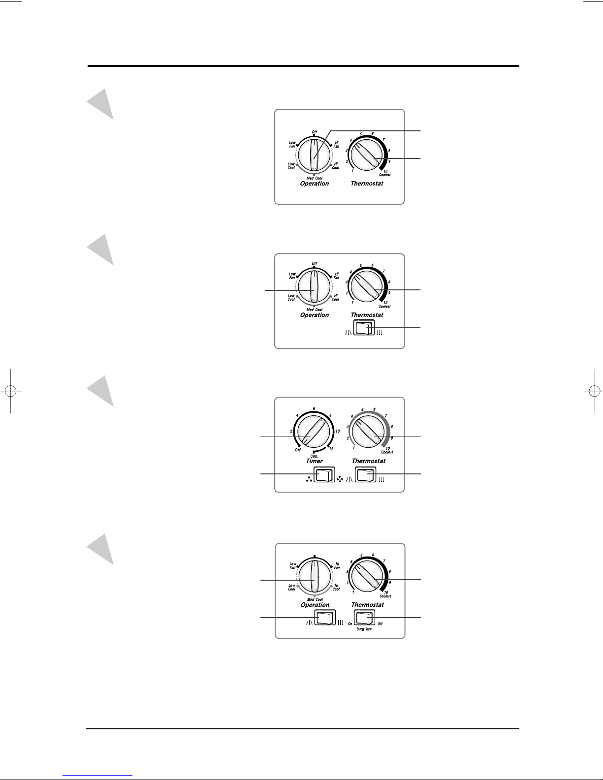
3-2 Controls and Components
AW0700B
AW07F0SAB
AW07F(A)0SEA
AW0800A
AW08F0SAA
AW09F(A)0SEA
AW09F0SAA
AW07F(A)1SDA
AW07F(A)1SEA
AW09F(A)1SEA
AW09F(A)1SDA
AW12F(A)1JBA
AW12F(A)1JDA
AW12F(A)1JEA
AW14F(A)1MB(C)A
AW18F(A)1MDA
AW1000A
AW10F0JAA
AW1200A
AW1400A
AW1800A
AW24F(A)0MCA
AW18F(A)1MEA
AWT24F(A)1MEA
AW18F(A)1MEB
AW24F(A)1MBC
AW18F1MBD
Operating
mode
selection dial
Operating mode
selection dial
Temperature
control dial
Temperature
control dial
Air flow blade swing switch
AW07F(A)2SBA
AW07F(A)2SDA
AW07F(A)2SEA
AW09F(A)2SBA
AW09F(A)2SBC
AW09F(A)2SEA
AW12F(A)2JB(C)A
AW12F(A)2JEA
AW2410C
AW14F(A)2MBA
AW18F(A)2MEA
AW18F(A)2MBA
AW24F(A)2MBB
AW18F2MBD
Fan speed switch
Timer
control dial
Operation mode
selection dial
Swing switch
Temperature control dial
Air flow blade swing switch
Thermostat control
Energy Saver switch
3-2 Samsung Electronics
3-2-1 THERMOSTAT
Installation and Operating Instructions
OFF :
When the room temperature is lowered by the air
conditioner, the gas within the thermostat will
contract and cause a break in the electric
contact. The compressor will then stop.
After the compressor stops, the room
temperature will rise
ON :
As the room temperature increases to a
selected level, the gas within the thermostat
expands, causing electric contact, which
provides the source of electric power to the
compressor. The room temperature will fall
and the cycle will repeat.
Control Operation :
By turning the control knob clockwise(toward
higher numbers), the temperatures will be cooler.
By turning the control knob counterclockwise
(toward lower numbers), the temperature will be
warmer .
Level 1 : Cool air will be supplied above 30~35°
Level 1 : Cool air will be ceased below 28~32.5°
Level 10 : Cool air will be supplied above 17.4~20.4°
Level 1 : Cool air will be ceased below 14.4~17.4°
3-2-2 Operation
The fan selector switch offers high and low fan cooling control levels to assure maximum comfort.
The two fan speeds allow you to economically circulate room air flow on days when intense cooling is
not required. When combined with the thermostat(set to call for conditioned air), these controls cool,
dehumidify, filter, and circulate room air, with the fan continuing to circulate air even when the
compressor is turned off.
3-2-3 Timer control
The timer enables the air conditioner to operate for a specified period of time, and then turns off automatically while the user is sleeping, shopping, etc.. To use this function, set the ti to the desired time, and
the air conditioner will automatically shut itself off after running for the selected period ot timer.
Utility bills can be reduced and comfortable temperatures maintained with the use of the timer.
For continuous operation, set the timer control to “continue”.
3-2-4 Air swing switch
• On ( ) : Automatic oscillation distributes the air flow throughout the room.
(controls left the right and left blade-V.)
• Off ( ) : Maintains a fixed direction of air flow, Set the Air switch to OFF at the instant the wave fins
come to the desired position.
Samsung Electronics 3-3

Installation and Operating Instructions
3-2-5 Fan speed switch
The fan speed switch offers high and low fan cooling control levels to assure maximum comfort.
The two fan speeds allow you to economically circulate room air flow on days when intense cooling is
not required. When combined with the thermostat(set to activate the air conditioner)hese controls cool,
dehumidify, filter, and circulate room air, with the fan continuing to circulate air while the compressor is
turned off.
3-2-6 Ventillation switch
Use the ventillation switch to exhaust stale air.
• Open position : The air inside the room circulates while the outdoor air is introduced inside.
• Closed position : The air inside the room circulates while the outdoor air is not introduced inside.
3-2-7 Energy Saver switch
The energy saver switch controls the fan.
• ENERGY SAVER OFF : The fan runs all the time, while the compressor cycle on and off.
• ENERGY SAVER ON : The fan and compressor cycle on and off together. This results in wider
variations of room temperature and humidity.
NOTE : If only the fan operation is desired, set the energy saver switch to “OFF”
The fan will not run with the switch setting combination at “FAN” of mode control and
“ON” of energy saver switch.
3-4 Samsung Electronics

4. Disassembly and Reassembly
4-1 Compressor Replacement Flow Chart
Locate cause of defect
Release refrigerant
Disconnect electrical wiring
from compressor
Cut refrigerant lines
from compressor
Plug disconnected lines
Replace compressor
Inspect electrical
wiring for defects,
and terminals for
correct and secure
connections
Y
Problem?
N
Corrective action
Solder discharge line
Y
Add oil as necessary
Solder suction line Use nitrogen gas
Check refrigerant oil level
Low oil level?
Perform soldering function
Fill system with
nitrogen gas
Check for leakage
Leakage?
Y
N
N
Release nitrogen gas?
Evacuate system
Samsung Electronics 4-1
Recharge system
Pinch and braze filling tube
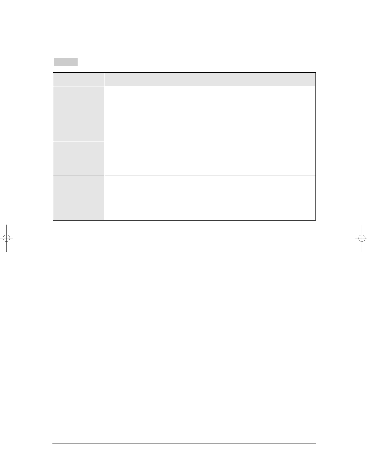
4-2 Checking the oil
Fill the transparent container with 10cc of oil, and then conduct the test.
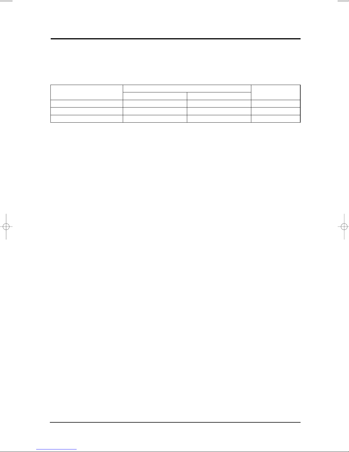
4-2-1 Oil quality
Condition of
Refrigerant Cycle
Normal
Over-heated
Compressor Damage
Color
Straw Y ellow
Brown Color
Dark Brown
Oil Condition
Odor
No Odor
Pungent oil
4-2-2 Replacing and refilling the refrigerant oil
1. Change the compressor - DO NOT recharge the oil as the compressor itself is
already charged.
2. Change the condenser .... add 50cc
3. Change the evaporator .... add 50cc
4. When the refrigerant is replaced .... add 30cc oil.
5. After vacuum is completed, the oil is filled through the high pressure side.
6. In the event of a refrigerant leak, generally it is not necessary to add oil.
(Unless the oil has leaked significantly.)
Remarks
Return with the system
-
Change the oil
Change the oil
4-2 Samsung Electronics
 Loading...