How it Works
Log In / Sign Up
Buy Points
How it Works
FAQ
Contact Us
Questions and Suggestions
Users
Samsung
Loading...
A
AV-MWH070EA0
7
AV-MWH072CA0
7
AV-MWMC023B1
AV-MWMC032B1
AV-MWMC040B1
AV-MWSC023B1TC
AV-MWTC040B1
AV-R600
2
AV-R601
3
AV-R610
AV-R620
4
AV-R620R
3
AV-R700
6
AV-R720
3
AV-R720R
3
AV-R730
AV-SHH100B10
AV-XC1H022EA
7
AV-XC1H023CA
AV-XC1H028EA
6
AV-XC1H032CA
AV-XC1H036EA
8
AV-XC1H040CA
AV-XC2H052B1
AV-XC2H056EA
8
AV-XC2H071EA
9
AV-XC4H052B2
AV-XC4H056EA
9
AV-XC4H060B1
AV-XC4H060B2
AV-XC4H071EA
8
AV-XC4H071EE
10
AV-XC4H072B3
AV-XC4H072CA
AV-XC4H072CE
2
AV-XC4H083CA
AV-XC4H090EB
6
AV-XC4H090EE
12
AV-XC4H100B3
AV-XC4H100B9
AV-XC4H100CE
2
AV-XC4H110B2
AV-XC4H110B3
AV-XC4H110CA
AV-XC4H110CE
2
AV-XC4H112EA
7
AV-XC4H128EA
6
AV-XC4H130CA
AV-XC4H140EA
8
AV-XC4H145B2
AV-XC4H145CE
2
AV-XCMH028EA
8
AV-XCMH032B3
AV-XCMH032CA
AV-XCMH036EA
9
AV-XCMH040CA
AV-XCMH052B1
AV-XCMH052CA
AV-XCMH056EA
9
AV-XCMH056EE
13
AV-XCMH060B1
AV-XCMH060EA
8
AV-XCSH023B3
AV-XCSH032B2
AV-XCSH036EE
12
AV-XCSH040CE
2
AV-XDBH022EA
4
AV-XDBH028EA
4
AV-XDBH032B1
AV-XDBH036EA
4
AV-XDBH056EA
4
AV-XDBH071EA
4
AV-XDDH060B1
AV-XDDH072B1
AV-XDHH112EA
5
AV-XDHH128EA
5
AV-XDHH130B1
AV-XDHH140EA
5
AV-XDSH022EA
4
AV-XDSH022EE
8
AV-XDSH028EA
4
AV-XDSH028EE
7
AV-XDSH036EA
7
AV-XDSH036EE
9
AV-XDSH045EA
4
AV-XDSH045EE
7
AV-XDSH052CA
AV-XDSH056EA
7
AV-XDSH071EA
8
AV-XDSH071EE
10
AV-XDSH072CA
AV-XDSH083CA
AV-XDSH090EA
2
AV-XDSH090EE
3
AV-XDSH110CA
AV-XDSH112EA
2
AV-XDSH112EE
5
AV-XDSH128EA
2
AV-XDSH130CA
AV-XDSH140EA
Loading...
Loading...
Nothing found
AV-XC4H145CE
User Manual
26 pgs
4.94 Mb
0
User Manual [es]
24 pgs
4.88 Mb
0
Table of contents
Loading...
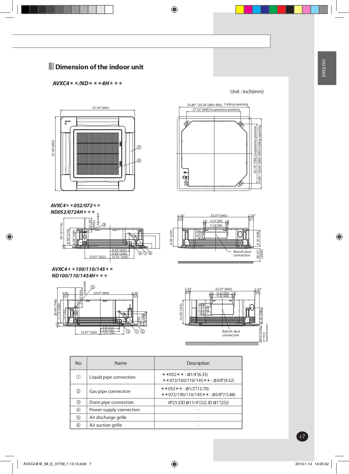
Samsung AV-XC4H145CE, AV-XC4H100CE, AV-XC4H110CE, AV-XC4H072CE User Manual
...
Samsung User Manual
Download
Loading...
+
18
hidden pages
Unhide
You need points to download manuals.
1 point = 1 manual.
You can buy points or you can get point for every manual you upload.
Buy points
Upload your manuals
 Loading...