

Samsung AVMWH032CA0, AVMWH072CA0, AVMWH040CA0, AVMWH052CA0, AVMWC020CA0 Installation Manual
...
E§§HNIKA
INSTALLATION MANUAL
MANUAL DE INSTALACIÓN
MANUEL D’INSTALLATION
MANUALE D’INSTALLZIONE
MANUAL DE INSTALAÇÃO
INSTALLATIONS-HANDBUCH
E°XEIPI¢IO E°KATA™TA™H™
азлнкмдсаь ий млнДзйЗдЦ
System Air Conditioner
Aire acondicionado sistemático
Climatiseur numérique multifonctionnel
Sistema Aria Condizionata
Sistema Ar Condicionado
Klimaanlage System
™‡ЫЩЛМ· ∫ПИМ·ЩИЫМФ‡
лЛТЪВПМ˚И ЗУБ‰Ы¯М˚И дУМ‰ЛˆЛУМВ
E S F I P D G R DB98-05180A(2)
A VMWH020CA0
A VMWH032CA0
A VMWH040CA0
A VMWH052CA0
A VMWH072CA0
A VMWH020EA(B)0
A VMWH026EA(B)0
A VMWH035EA(B)0
A VMWH052EA(B)0
A VMWH070EA(B)0
Heat pump
A VMWC020CA0
A VMWC032CA0
A VMWC040CA0
A VMWC052CA0
A VMWC072CA0
A VMWC020EA(B)0
A VMWC026EA(B)0
A VMWC035EA(B)0
A VMWC052EA(B)0
A VMWC070EA(B)0
Cooling only
ENGLISH
ESPAÑOL
FRANÇAIS
ITALIANO
PORTUGUÊS
DEUTSCH
RUSSIAN
■ Parts List . . . . . . . . . . . . . . . . . . . . . . . . . . . . . . . . . . . . . . . . . . . 24
OO
OO
PPPPTTTTIIIIOOOONNNNAAAALL
LL
AA
AA
CCCCCCCCEEEESSSSSSSSOOOORRRRIIIIEEEESS
SS
Chapter
Contents
E-2
■ Preparation for Installation . . . . . . . . . . . . . . . . . . . . . . . . . . . . . . . 4
■ Deciding on Where to Install the Indoor Unit . . . . . . . . . . . . . . . . . 5
■ Fixing the Installation Plate . . . . . . . . . . . . . . . . . . . . . . . . . . . . . . . 8
■ Electronic Expansion Valve Kit Installation . . . . . . . . . . . . . . . . . . . 9
■ Connecting the Refrigerant Pipe . . . . . . . . . . . . . . . . . . . . . . . . . 12
■ Cutting / Flaring the Pipes . . . . . . . . . . . . . . . . . . . . . . . . . . . . . . 13
■ Performing Leak Test & Insulation . . . . . . . . . . . . . . . . . . . . . . . . 14
■ Drain Hose Installation . . . . . . . . . . . . . . . . . . . . . . . . . . . . . . . . . 15
■ Connecting the Connection Cord . . . . . . . . . . . . . . . . . . . . . . . . . 16
■ Assigning Address to Indoor Unit . . . . . . . . . . . . . . . . . . . . . . . . . 17
■ Additional Functions . . . . . . . . . . . . . . . . . . . . . . . . . . . . . . . . . . . 18
■ Bio-pure Filter Installation (optional) . . . . . . . . . . . . . . . . . . . . . . . 19
■ Troubleshooting . . . . . . . . . . . . . . . . . . . . . . . . . . . . . . . . . . . . . . 20
WW
WW
AAAALLLLLL
LL
--
--
MMMMOOOOUUUUNNNNTTTTEEEEDD
DD
TT
TT
YYYYPPPPEE
EE
II
II
NNNNSSSSTTTTAAAALLLLLLLLAAAATTTTIIIIOOOONN
NN
Chapter
■ Preparation for Installation . . . . . . . . . . . . . . . . 4
■ Deciding on Where to Install the Indoor Unit . . . 5
■ Fixing the Installation Plate . . . . . . . . . . . . . . . . 8
■ Electronic Expansion Valve Kit Installation . . . . 9
■ Connecting the Refrigerant Pipe . . . . . . . . . . . 12
■ Cutting / Flaring the Pipes . . . . . . . . . . . . . . . . 13
■ Performing Leak Test & Insulation . . . . . . . . . 14
■ Drain Hose Installation . . . . . . . . . . . . . . . . . . 15
■ Connecting the Connection Cord . . . . . . . . . . 16
■ Assigning Address to Indoor Unit . . . . . . . . . . 17
■ Additional Functions . . . . . . . . . . . . . . . . . . . . 18
■ Bio-pure Filter Installation (optional) . . . . . . . . 19
■ Troubleshooting . . . . . . . . . . . . . . . . . . . . . . . 20
WW
WW
AAAALLLLLL
LL
--
--
MMMMOOOOUUUUNNNNTTTTEEEEDD
DD
TT
TT
YYYYPPPPEE
EE
II
II
NNNNSSSSTTTTAAAALLLLLLLLAAAATTTTIIIIOOOONN
NN
Chapter
E-3
ENGLISH
Preparation for Installation
When deciding on the location of the air conditioner with the owner,
the following restrictions must be taken into account.
General
Do NOT install the air conditioner in a location where it will come into
contact with the following elements:
◆
Combustible gases
◆
Saline air
◆
Machine oil
◆
Sulphide gas
◆
Special environmental conditions
If you must install the unit in such conditions, first consult your dealer.
E-4
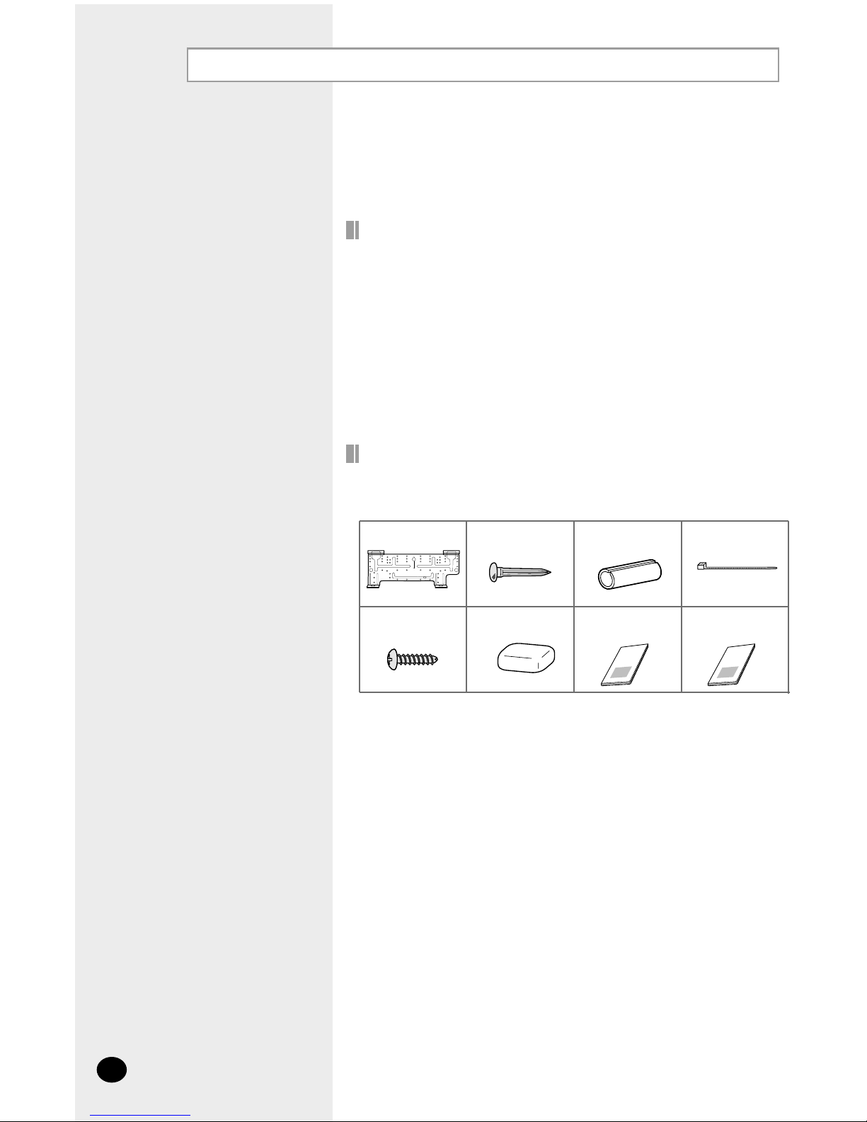
Accessories
◆ The following accessories are supplied with the indoor unit.
The quantities are indicated in parentheses.
Installation plate (1) Insulation refrigerant
pipe (1)
Cement nail (6)
Cable tie (4)
Tapped screw (6) Putty (1) Owner’s instructions
(1)
Installation manual
(1)
O
W
N
E
R
’
S
I
N
S
T
R
U
C
T
I
O
N
S
S
p
l
u
t
-
t
y
p
e
R
o
o
m
A
i
r
C
o
n
d
i
t
i
o
n
e
r
O
W
N
E
R
’
S
I
N
S
T
R
U
C
T
I
O
N
S
S
p
l
u
t
-
t
y
p
e
R
o
o
m
A
i
r
C
o
n
d
i
t
i
o
n
e
r
Deciding on Where to Install the Indoor Unit
Indoor Unit
◆
There must be no obstacles near the air inlet and outlet.
◆
Install the indoor unit on a wall that can support its weight.
◆
Maintain sufficient clearance around the indoor unit.
◆
Make sure that the water dripping from the drain hose runs away correctly
and safely.
◆
The indoor unit must be installed in this way, that they are out of public
access. (Not touchable by the users)
E-5
ENGLISH
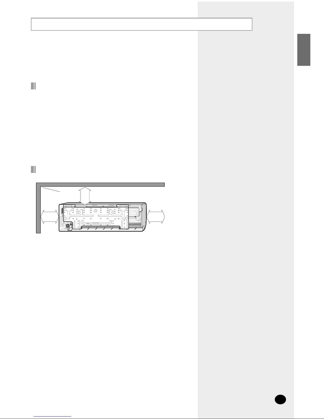
Space Requirements for Indoor Unit
125mm
or more
125mm
or more
30mm
or more
E-6
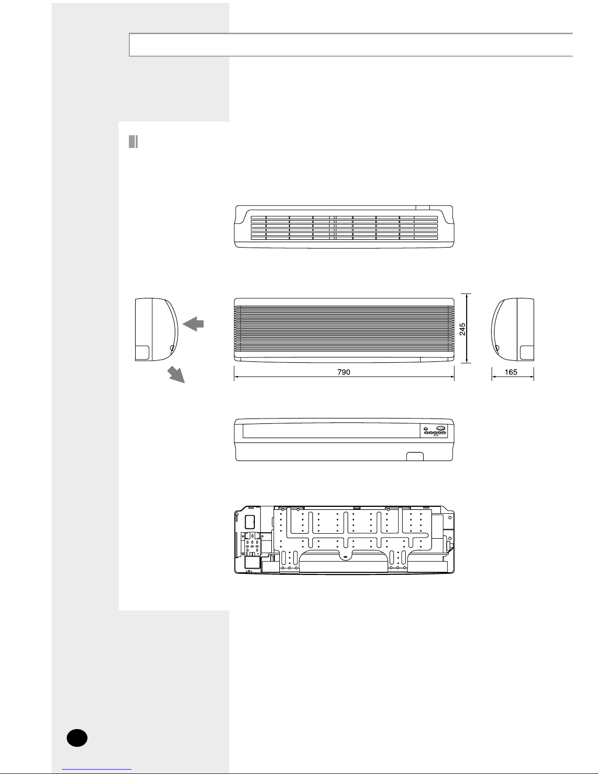
Deciding on Where to Install the Indoor Unit (cont.)
Drawing of the indoor unit
✴✴
020/026/032/035/040
✴✴
Unit : mm
Air In
Front view
Rear view
Air out
E-7
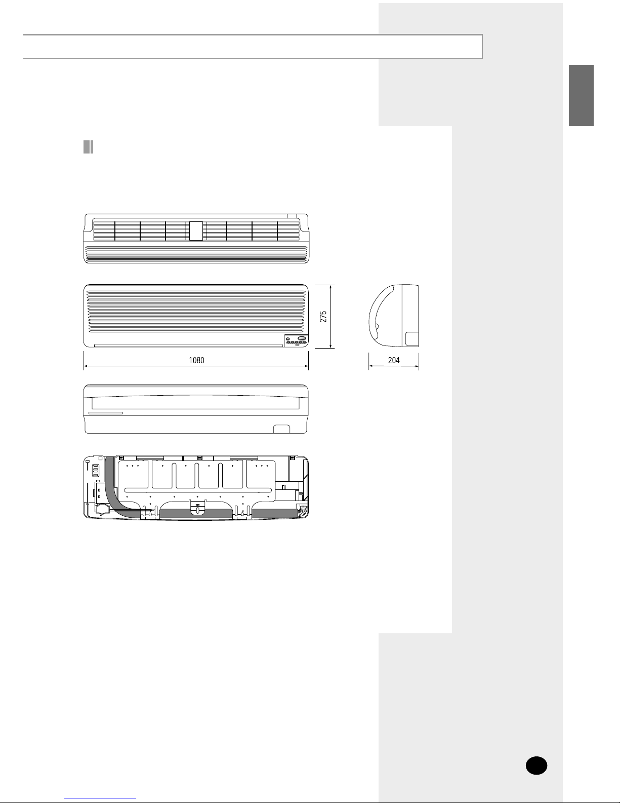
ENGLISH
✴✴
052/070/072
✴✴
Drawing of the indoor unit
Front view
Rear view
Unit : mm
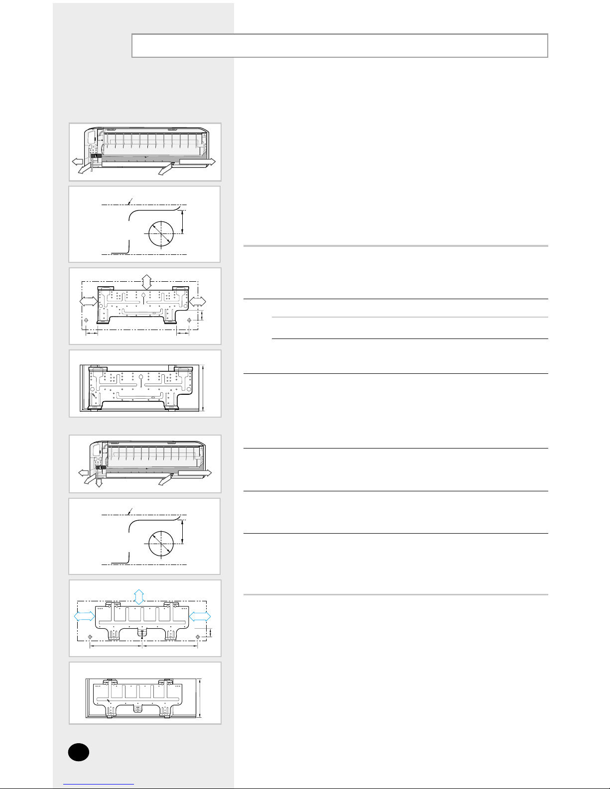
Fixing the Installation Plate
E-8
60
30
252
275
14090
410~730
Before fixing the installation plate to a wall or window frame, you
must determine the position of the 65 mm hole through which the
cable, piping and hose pass to connect the indoor unit up to the
outdoor unit. When facing the air conditioner in position on the wall,
the piping and cable can be connected from the:
◆ Right
◆ Left
◆ Underside;
✴✴
052/070/072
✴✴
◆ Rear (right or left)
1 Determine the position of the pipe and drain hose hole using the right
figure and drill the hole with an inner diameter of 65 mm so that it slants
slightly downwards.
2 If you are fixing the indoor unit to a... Then follow Steps...
Wall 3.
Window frame 4 to 6.
3 Fix the installation plate to the wall in a manner appropriate to the weight
of the indoor unit.
➢ If you are mounting the plate on a concrete wall with anchor
bolts, the anchor bolts must not project by more than 20 mm.
4 Determine the positions of the wooden uprights to be attached to the
window frame.
5 Attach the wooden uprights to the window frame in a manner appropriate
to the weight of the indoor unit.
6 Using tapped screws, attach the installation plate to the wooden uprights,
as illustrated in the last figure opposite.
✴✴
020/026/032/035/040
✴✴
30mm
Installation plate
Pipe hole
(
Ø
65mm)
(Unit : mm)
(Unit : mm)
60
45
255
325
415512
410~730
✴✴
052/070/072
✴✴
45mm
Installation plate
Pipe hole
(
Ø
65mm)
(Unit : mm)
(Unit : mm)

Electronic Expansion Valve Kit Installation
1
Decide an installation place that can support the electronic expansion
valve kit.
2
Connect the “IN” refrigerant pipe to the outdoor unit.
3
Connect the “OUT” refrigerant pipe to each indoor unit(A, B and C).
◆
The liquid and gas pipes should not be crossed when piping connection.
4
Insulate the connection piping. Ajoint part of pipe needs double
thickness of insulation.
5
The expansion valve has to be installed that the user has no access
to it. (built-in type)
Nylon band
Electronic
Expansion
valve
body
E-9
ENGLISH
Connection of refrigerant piping & Insulation

Electronic Expansion Valve Kit Installation (cont.)
E-10
Wiring & Assigning address
1
Connect the AC power cable and communication cable from the outdoor
unit to terminal, then connect the cable to another electronic expansion
valve kit.
Room A
Room B
Outdoor
unit
Another
distributor kit
Room C
2
Connect the AC power cable and communication cable to each indoor
unit (A, B and C).
3
Align the SW51, SW52 and SW53’s addresses with A, B and C indoor
units’.
SW51
SW52
SW53
A
B
C
CN63(Y ellow)
CN62(Blue)
CN61(White)
Switch No.
Appropriate indoor unit
(Electronic expansion valve)
Connector No.

◆
The numbers which is displayed on left are the status of indoor unit checking
status through communication with same outdoor unit.
(If it indicates 1, 3 and 7, that means the ADDRESS of indoor unit is
set to 1, 3 and 7.)
◆
The numbers which is displayed on right indicate the ADDRESS of SW51,
SW52 and SW53 in sequential. (If it indicates 0, 1 and 2, that means the
SW51 is set to 0, the SW52 is set to 1, and the SW53 is set to 2.)
◆
If the communication error occurs in distributor, the Er↔C0 message will be
shown on the display alternatively.
E-11
ENGLISH
Function of Display
◆
If you press a KEY on the PCB, the display will show you a step of appropriate
electronic expansion valve.
KEY function
K1
K2
K3
K4
Step of electronic expansion valve A
Step of electronic expansion valve B
Step of electronic expansion valve C
-
19
(19 x 10 =
190 STEP)
-
KEY No.
Meaning
Example

E-12
Connecting the Refrigerant Pipe
◆
If the pipes must be shortened refer to page 13.
NNNNoooottttee
ee
Outer Diameter Torque (kgf•cm)
6.35 mm (1/4") 144~176
9.52 mm (3/8") 333~407
12.70 mm (1/2") 504~616
15.88 mm (5/8") 630~770
19.05 mm (3/4") 990~1210
22.23 mm (7/8") 990~1210
4 Cut off any excess foam insulation.
5 If necessary, bend the pipe round, along the bottom of the indoor unit and
out through the appropriate hole, taking care to ensure that:
◆ The piping does not jut out from the rear of the indoor unit
◆ The bending radius is 100 mm or more
6
It would be necessary to double the insulation thickness(10mm or
more) to prevent condensation even on the insulator when if the
installed area is warm and humid.
There are two refrigerant pipes of different diameters:
◆ A smaller one for the liquid refrigerant
◆ A larger one for the gas refrigerant
A short length of piping is already fitted to the air conditioner. You
must extend this piping using assembly piping (optionally supplied).
The connection procedure for the refrigerant piping varies according
to the exit position of the piping from the indoor unit, as seen when
facing the air conditioner in position on the wall:
◆ Right (A)
◆ Left (B)
◆ Underside (C) ; ✴✴052/070/072✴✴
◆ Rear
1 With a knife, cut out the appropriate knock-out piece on the rear of the
indoor unit (unless you are connecting directly from the rear).
2 Smooth the cut edges.
3 Remove the protection caps on the pipes and connect the assembly piping
to each pipe, tightening the nuts, first manually and then with a wrench,
applying the following torque.
A
B
C

Cutting / Flaring the Pipes
E-13
ENGLISH
Outer Diameter Torque (kgf•cm)
6.35 mm (1/4") 144~176
9.52 mm (3/8") 333~407
12.70 mm (1/2") 504~616
15.88 mm (5/8") 630~770
19.05 mm (3/4") 990~1210
22.23 mm (7/8") 990~1210
Make sure that you have the required tools available (pipe cutter, reamer,
flaring tool and pipe holder).
1
If you wish to shorten the pipes, cut it with a pipe cutter, taking care to
ensure that the cut edge remains at a 90° angle with the side of the pipe.
Refer to the illustrations below for examples of edges cut correctly and
incorrectly.
2
To prevent any gas from leaking out, remove all burrs at the cut edge of the
pipe, using a reamer.
3
Slide a flare nut on to the pipe and modify the flare.
4
Check that the flaring is correct, referring to the illustrations below for
examples of incorrect flaring.
5
Align the pipes and tighten the flare nuts first manually and then with
a wrench, applying the following torque.
6
Outer Diameter (D) Depth (A)
6.35 mm (1/4") 1.3mm
9.52 mm (3/8") 1.8mm
12.70 mm (1/2") 2.0mm
15.88 mm (5/8") 2.2mm
19.05 mm (3/4") 2.2mm
22.23 mm (7/8") 2.2mm
90
O
Oblique Rough Burr
Inclined Damaged Surface Cracked Uneven Thickness
◆
CCCCAAAAUUUUTTTTIIIIOOOONN
NN
In case of welding the pipe, you must weld with nitrogen
gas blowing.

Performing Leak Test & Insulation
To check for gas leaks on the indoor unit, check the connection part
of each refrigerant pipe by using a leak detector.
Once you have checked that there are no leaks in the system,
you can insulate the piping and hose.
To avoid condensation problems, place T13.0 or thicker Acrylonitrile
Butadien Rubber separately around each refrigerant pipe.
1
Wind insulating tape around the pipes.
2
Finish wrapping insulating tape around the rest of the pipes leading to the
outdoor unit.
3
◆
Always make the seam of pipes face upwards.
NNNNoooottttee
ee
Leak Test
Insulation
Insulation
Be sure to overlap
the insulation
Indoor Unit
CCCCAAAAUUUUTTTTIIIIOOOONN
NN
Must fit tightly against
body without any gap.
No gap
NBR(T13.0 or thicker)
E-14

Drain Hose Installation
E-15
ENGLISH
To install the drain hose, proceed as follows.
1 If necessary, connect the 2-metre extension to the drain hose.
2 If you are using the extension, insulate the inside part of the extension
drain hose with a shield.
3 Pass the drain hose under the refrigerant piping, taking care to keep the
drain hose tight.
4 Pass the drain hose through the hole in the wall, making sure that it is
sloping downwards, as shown in the illustrations above.
Care must be taken when installing the drain hose for the indoor unit to ensure that any condensation
water is correctly drained outside. When passing the drain hose through the 65 mm hole drilled in the
wall, check that none of the following situations occur.
The hose must
NOT slope
upwards.
The end of the drain
hose must NOT be
placed in water.
Do NOT bend the
hose in different directions.
Keep a clearance of
at least 5 cm between
the end of the hose
and the ground.
Do NOT place the
end of the drain hose
in a hollow.
5 cm
less
Ditch
Shield
Drain hose
Extension drain hose

Connecting the Connection Cord
Wiring Diagram
The indoor unit is powered from the outdoor unit via the connection cord.
Remove the screw on the electrical component box and remove the cover
plate.
1
Route the connection cord through the side of the indoor unit and connect
the cable to terminals; refer to the figure below.
2
Route the other end of the cable to the outdoor unit through the ceiling &
the hole on the wall.
3
Reassemble the electrical component box cover, carefully tightening the
screw.
4
Indoor Unit
Outdoor Unit
PowerCommunication
Next Indoor unit(Power)
Next Indoor unit
(Communication)
E-16

Assigning Address to Indoor Unit
Before installing the indoor unit, assign an address to the indoor unit
according to the air conditioning system plan.
1
The address of the indoor unit is assigned by adjusting MAIN(SW02) and
RMC(SW01) rotary switches.
2
The MAIN address is for communication between the indoor unit and the outdoor
unit. Therefore, you must set it to operate the air conditioner properly.
3
It is required to set the RMC address if you install the wired remote controller
and/or the centralized controller.
4
If you install optional accessories such as the wired remote controller, centralized
controller, etc. see an appropriate installation manual.
5
If an optional accessory is not installed, you do not have to set the RMC
address. However, adjust K1 and K2 switches of the SW03 DIP switch to
"ON" position in this case.
6
Set the MAIN address by adjusting the rotary switch(SW02) from 0 to F. Each
indoor unit connected to the same outdoor unit must have different address.
i. e. If an indoor unit does not have an optional accessory and its MAIN address
is "4"
7
E-17
ENGLISH
K1 K2 K3 K4
K5 K6 K7 K8
K9
K10
K11
K12
SW03 SW04
SW05
SW01 RMC SW02 MAIN
K1 K2 K3 K4
K5 K6 K7 K8
K9
K10
K11
K12
SW03
SW04
SW05
SW01 RMC
SW02 MAIN

Additional Functions
E-18
Compensation for lost temperature in heating operation
◆ Reduces the difference between an actual room temperature and a sensed
temperature by the air conditioner when heating.
Adjusting filter cleaning cycle
◆ You can adjust the cycle for filter sign indicator.
K5 K6 K7 K8
SW04
K5 K6 K7 K8
SW04
K5 2°C compensation 5°C compensation
Switch No.
Switch ON Switch OFF
Control of electronic expansion valve at the indoor unit off
◆ When an indoor unit off makes refrigerant noise, set K11 to OFF position to
reduce the noise. However, if a distributor kit is installed, K11 must be at ON
position.
K9 K10
K1 1 K12
SW05
K11
Electronic expansion valve
step 80
Electronic expansion valve
step 0 (Sub cool control)
Switch No.
Switch ON Switch OFF
K6 1000 hours 2000 hours
Switch No.
Switch ON Switch OFF

Bio-pure Filter Installation (optional)
E-19
ENGLISH
The air conditioner can be fitted with a Bio-Pure or deodorizing filter to remove
minute dust particles or odours. The service life of the filter is approximately
three months depending on the time during which the air conditioner is used.
Bio-pure filter
Deodorizing filter
Deodorizing
filter
1
Bio-pure filter
1
Accessories
Insert the filter in the filter holder and press the three tabs until you hear
a click.
2
1
Open the front grille by pulling on the tabs on the lower right and left side
of the indoor unit.
3
Take out the existing filter and replace it with the new one.
4
Do not remove the packing from a bio-pure filter until you wish
to use the filter, as it will lose its properties.
NNNNoooottttee
ee
Remove the vinyl packing from the filter.

Troubleshooting
E-20
Displayed on appropriate indoor
unit which is operating
Displayed on appropriate indoor
unit which is operating
Displayed on appropriate indoor
unit which is operating
Displayed on appropriate indoor
unit which is operating
Displayed on outdoor unit
1. Error of indoor unit: Displayed
on the indoor unit regardless
of operation
2. Error of outdoor unit:
Displayed on the indoor unit
which is operating
Power reset
Error of temperature sensor in indoor unit
(OPEN/SHORT)
Error of heat exchanger sensor in indoor unit
Error of heat exchanger OUT sensor in indoor unit
Error of outlet temperature sensor in indoor unit
(OPEN/SHORT): For heat pump models only
Error of mixed operation
Error of indoor fan motor:
Below 450RPM for 15 minutes
Error of outdoor temperature sensor
Error of COND sensor
Error of DISCHARGE sensor
1. No communication for 2 minutes between
indoor unit and outdoor unit (communication error for more than 2 minutes)
2. Indoor unit receiving the communication
error from outdoor unit
3. Outdoor unit tracking 3 minute error
4. When sending the communication error
from outdoor unit due to the mismatching
of the communication numbers and
installed numbers after completion of
tracking (communication error for more
than 2 minutes)
XXX
XXX
XXXX
X
X
X
XXX
X
X
X
X
XX
X
X
● On Flickering X Off
Detection of errors
◆ If an error occurs during the operation, an LED flickers and the operation is stopped except the LED.
◆ If you re-operate the air conditioner, it operates normally at first, then detect an error again.
LED Display
Operating
Indicators
Abnormal conditions
Green Red
LED Display on the indoor unit

E-21
ENGLISH
LED Display
● On Flickering X Off
◆
If you turn off the air conditioner when the LED is flickering, the LED is also turned off.
◆
If you re-operate the air conditioner, it operates normally at first, then detects an error again.
Displayed on appropriate indoor
unit which is operating
Displayed on outdoor unit
Displayed on appropriate indoor
unit which is operating
Displayed on outdoor unit
Self-diagnostic error
(including the indoor unit not detected)
1.
Error of electronic expansion valve close
2.
Error of electronic expansion valve open
3. Breakaway of EVA OUT sensor
4. Breakaway of EVA IN sensor
5. Breakaway of COND MID sensor
6.
2nd detection of refrigerant completely leak
7.
2nd detection of high temperature COND
8.
2nd detection of high temperature DISCHARGE
9. COMP DOWN due to 2nd detection of
low pressure switch
10. Error of reverse phase
1 1.
Compressor down due to 6th detection of
freezing
12.
Self-diagnosis of condensation sensor (G8, G9)
13.
Compressor down due to condensation
ratio control
Error of float switch
Error of setting option switches for optional accessories
EEPROM error
EEPROM option error
X X
XX
XX
XXX
XX
X
Operating
Indicators
Abnormal conditions
Green Red

E-22
Troubleshooting (cont.)
Explanation
Display
Error of communication between the outdoor unit and the wired
remote controller
Error of communication between the indoor unit and the wired
remote controller
Breakaway of indoor unit eva sensor
Breakaway of indoor unit eva out sensor
Open error of electronic expansion valve
Close error of electronic expansion valve
Breakaway of eva mid and eva out sensors in indoor unit
Error of float switch
OPEN/SHORT error of room sensor in indoor unit
OPEN/SHORT error of eva in sensor in indoor unit
OPEN/SHORT error of eva out sensor in indoor unit
EEPROM error
EEPROM option error
Error of fan starting
Error of outdoor unit
Communication
errors
Displays related to
indoor unit
(x : 0~F)
For the details, refer to
the installation manual
of the outdoor unit.
Remark
The order of priority : EA→ Eb → Cx → dx → bx → Ax → Fx → ox → qx → rx → sx → tx → Ux → vx →Eo
- In case that the same error displays from multi-indoor units, the one having the faster address
has the priority.
x
x
x
x
x
x
x
x
x
x
x
x
Wired remote controller
◆ If an error occurs, is displayed on the wired remote controller.
◆ If you would like to see an error code, press the Test button.

■ Parts List . . . . . . . . . . . . . . . . . . . . . . . . . . . . . . . . . 24
OO
OO
PPPPTTTTIIIIOOOONNNNAAAALL
LL
AA
AA
CCCCCCCCEEEESSSSSSSSOOOORRRRIIIIEEEESS
SS
Chapter
E-23
ENGLISH

Parts List
E-24
Wired remote
controller
1
Cable-tie2Cable clamp
5
M4x16 tapped
screw
7
Indoor unit power
drawing cable
1
Wired Remote Controller Accessories
Centralized
controller
1
Cable-tie2Cable clamp
5
M4x16 tapped
screw
7
Centralized Controller Accessories
Transmitter
1
Transmitter
power cable
1
Transmitter
communication cable
1
T ransmitter Accessories
Owner’s
instructions
1
Installation
manual
1
Function
controller
1
Cable-tie2Cable clamp
6
M4x16 tapped
screw
7
Function Controller Accessories
Owner’s
instructions
1
Installation
manual
1
Owner’s
instructions
1
Installation
manual
1
Installation
manual
1
Wireless
remote controller
1
Battery
2
Remote
control holder
1
STS 2S-2x10
tapped screw
2
Owner’s
instructions
1
Installation
manual
1
Wireless Remote Controller Accessories

Memo
E-25
ENGLISH

ELECTRONICS
THIS AIR CONDITIONER IS MANUFACTURED BY:
ESTE AIRE ACONDICIONADO HA SIDO FABRICADO POR:
CE CLIMATISEUR EST FABRIQUE PAR:
QUESTO CONDIZIONATORE D’ARIA È PRODOTTO DA:
ESTE APARELHO DE AR CONDICIONADO É FABRICADO POR:
DIESE KLIMAANLAGE IST FABRIZIERT VON:
AYTH H ™Y™KEYH KATA™KEYA™THKE A¶O:
щнйн дйзСасайзЦк абЙйнйЗгЦз оакейв:
Printed in Korea
 Loading...