

Samsung AVMBH072CA0, AVMBH052CA0, AVMBH026EA0, AVMBH020EA0, AVMBH035EA0 Installation Manual
...
E§§HNIKA
ENGLISH
INSTALLATION MANUAL
MANUAL DE INSTALACIÓN
MANUEL D’INSTALLATION
MANUALE D’INSTALLZIONE
MANUAL DE INSTALAÇÃO
INSTALLATIONS-HANDBUCH
E°XEIPI¢IO E°KATA™TA™H™
азлнкмдсаь ий млнДзйЗдЦ
System Air Conditioner
Aire acondicionado sistemático
Climatiseur numérique multifonctionnel
Sistema Aria Condizionata
Sistema Ar Condicionado
Klimaanlage System
™‡ЫЩЛМ· ∫ПИМ·ЩИЫМФ‡
лЛТЪВПМ˚И ЗУБ‰Ы¯М˚И дУМ‰ЛˆЛУМВ
ESPAÑOL
FRANÇAIS
ITALIANO
PORTUGUÊS
DEUTSCH
E S F I P D G R DB98-05178A(2)
A VMBH020CA0
A VMBH032CA0
A VMBH040CA0
A VMBH052CA0
A VMBH072CA0
A VMBH020EA(B)0
A VMBH026EA(B)0
A VMBH035EA(B)0
A VMBH052EA(B)0
A VMBH070EA(B)0
Heat pump
A VMBC020CA0
A VMBC032CA0
A VMBC040CA0
A VMBC052CA0
A VMBC072CA0
A VMBC020EA(B)0
A VMBC026EA(B)0
A VMBC035EA(B)0
A VMBC052EA(B)0
A VMBC070EA(B)0
Cooling only
RUSSIAN

■ Parts List . . . . . . . . . . . . . . . . . . . . . . . . . . . . . . . . . . . . . . . . . . . 26
OO
OO
PPPPTTTTIIIIOOOONNNNAAAALL
LL
AA
AA
CCCCCCCCEEEESSSSSSSSOOOORRRRIIIIEEEESS
SS
Chapter
Contents
E-2
■ Preparation for Installation . . . . . . . . . . . . . . . . . . . . . . . . . . . . . . . 4
■ Deciding on Where to Install the Indoor Unit . . . . . . . . . . . . . . . . . 5
■ Indoor Unit Installation . . . . . . . . . . . . . . . . . . . . . . . . . . . . . . . . . . 8
■ Purging the Unit . . . . . . . . . . . . . . . . . . . . . . . . . . . . . . . . . . . . . . . 9
■ Connecting the Refrigerant Pipe . . . . . . . . . . . . . . . . . . . . . . . . . 10
■ Cutting/Flaring the Pipes . . . . . . . . . . . . . . . . . . . . . . . . . . . . . . . 11
■ Performing Leak Test & Insulation . . . . . . . . . . . . . . . . . . . . . . . . 12
■ Drain Hose Installation . . . . . . . . . . . . . . . . . . . . . . . . . . . . . . . . . 13
■ Connecting the Connection Cord . . . . . . . . . . . . . . . . . . . . . . . . . 15
■ Increasing Fan Speed . . . . . . . . . . . . . . . . . . . . . . . . . . . . . . . . . 16
■ Assigning Address to Indoor Unit . . . . . . . . . . . . . . . . . . . . . . . . . 18
■ Additional Functions . . . . . . . . . . . . . . . . . . . . . . . . . . . . . . . . . . . 19
■ Drain Pump Installation (optional) . . . . . . . . . . . . . . . . . . . . . . . . 20
■ Troubleshooting . . . . . . . . . . . . . . . . . . . . . . . . . . . . . . . . . . . . . . 22
DD
DD
UUUUCCCCTT
TT
((
((
BBBBUUUUIIIILLLLTT
TT
--
--
IIIINN
NN
)))) II
II
NNNNSSSSTTTTAAAALLLLLLLLAAAATTTTIIIIOOOONN
NN
Chapter
■ Preparation for Installation . . . . . . . . . . . . . . . . . 4
■ Deciding on Where to Install the Indoor Unit . . . 5
■ Indoor Unit Installation . . . . . . . . . . . . . . . . . . . . 8
■ Purging the Unit . . . . . . . . . . . . . . . . . . . . . . . . 9
■ Connecting the Refrigerant Pipe . . . . . . . . . . . 10
■ Cutting/Flaring the Pipes . . . . . . . . . . . . . . . . . 11
■ Performing Leak Test & Insulation . . . . . . . . . . 12
■ Drain Hose Installation . . . . . . . . . . . . . . . . . . 13
■ Connecting the Connection Cord . . . . . . . . . . 15
■ Increasing Fan Speed . . . . . . . . . . . . . . . . . . . 16
■ Assigning Address to Indoor Unit . . . . . . . . . . 18
■ Additional Functions . . . . . . . . . . . . . . . . . . . . 19
■ Drain Pump Installation (optional) . . . . . . . . . . 20
■ Troubleshooting . . . . . . . . . . . . . . . . . . . . . . . . 22
DD
DD
UUUUCCCCTT
TT
((
((
BBBBUUUUIIIILLLLTT
TT
--
--
IIIINN
NN
)))) II
II
NNNNSSSSTTTTAAAALLLLLLLLAAAATTTTIIIIOOOONN
NN
Chapter
E-3
ENGLISH
Preparation for Installation
When deciding on the location of the air conditioner with the owner,
the following restrictions must be taken into account.
General
Do NOT install the air conditioner in a location where it will come into
contact with the following elements:
◆
Combustible gases
◆
Saline air
◆
Machine oil
◆
Sulphide gas
◆
Special environmental conditions
If you must install the unit in such conditions, first consult your dealer.
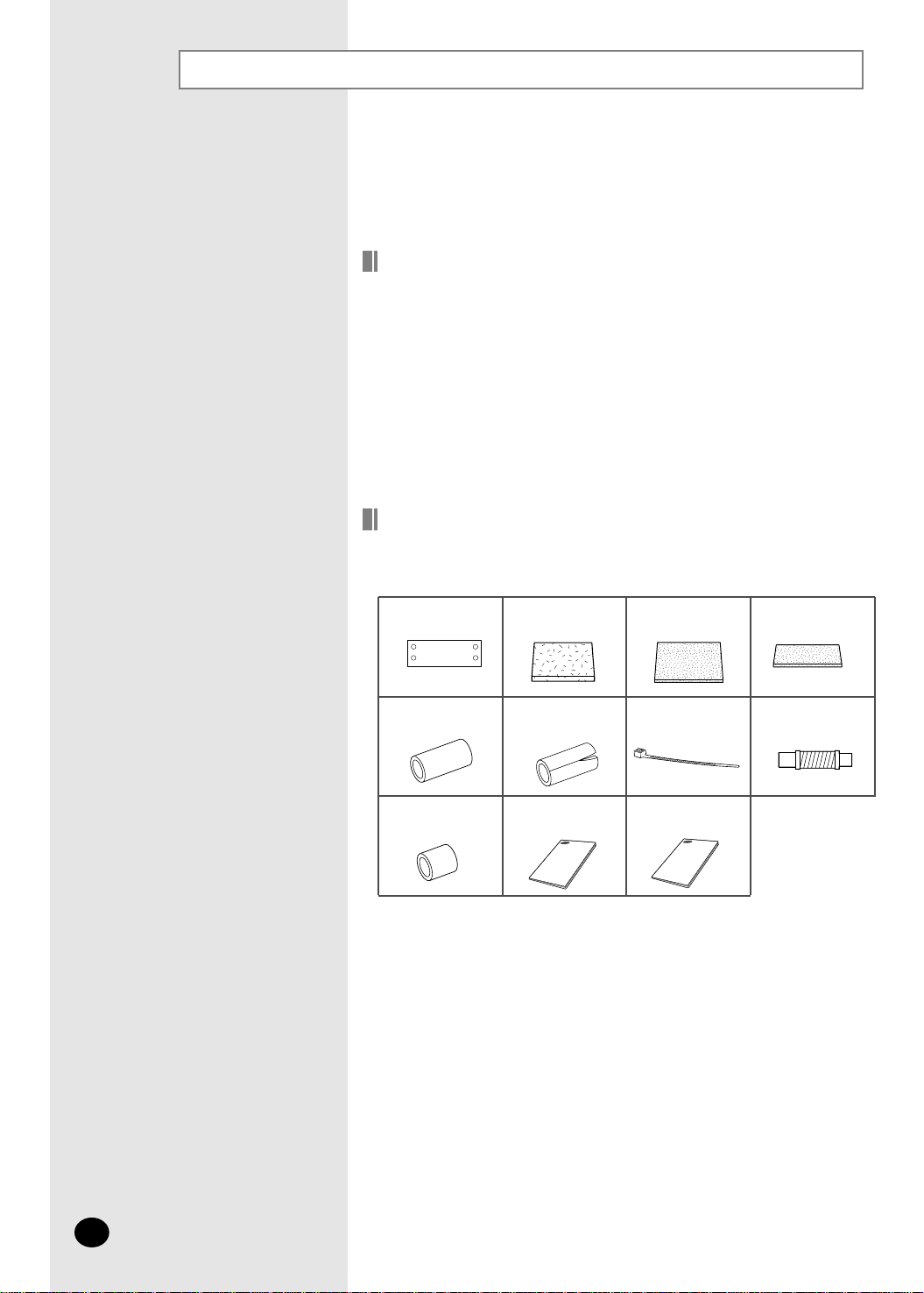
Accessories
◆ The following accessories are supplied with the indoor unit.
The quantities are indicated in parentheses.
E-4
Pattern sheet (1) Insulation (2)Insulation cover
drain (1)
Insulation cover
band (1)
Insulation pipe (2)
Insulation drain
hose (2)
Installation manual
(1)
Owner’s Instructions
(1)
Cable-tie (5) Flexible hose (1)
Insulation drain sub
(1)
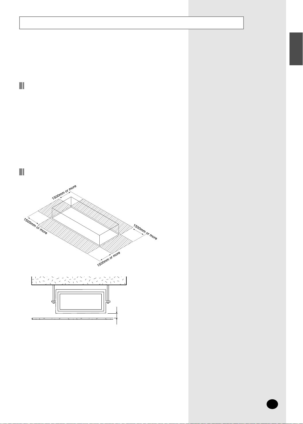
Deciding on Where to Install the Indoor Unit
Indoor Unit
E-5
ENGLISH
You must have 5mm or more space between the
ceiling and the bottom of indoor unit. Otherwise,
the noise from the vibration of indoor unit may
bother the user.
5mm or more
◆
There must be no obstacles near the air inlet and outlet.
◆
Install the indoor unit on a ceiling that can support its weight.
◆
Maintain sufficient clearance around the indoor unit.
◆
Make sure that the water dripping from the drain hose runs away correctly
and safely.
◆
The indoor unit must be installed in this way, that they are out of public
access. (Not touchable by the users)
◆
After connecting a chamber, insulate the connection part between the indoor
unit and the chamber with t10 or thicker insulation. Otherwise, there can be
air leak or dew from the connection part.
Space Requirements for Indoor Unit
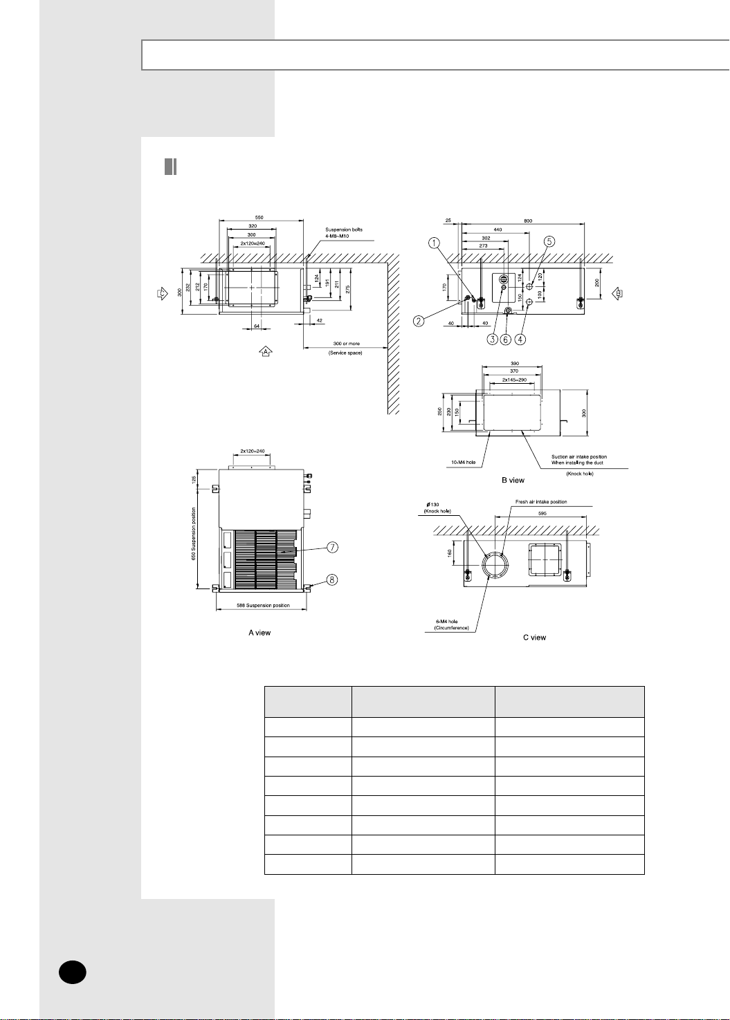
Drawing of the indoor unit
Unit : mm
✴✴020/026/032/035/040✴✴
1
2
3
4
5
6
7
8
Liquid pipe connection
Gas pipe connection
Drain pipe connection
Interunit wiring port
Power wiring port
Drain pipe connection
Air filter
Hook
ø6.35 Flare
ø12.70 Flare
OD29 ID25
(without drain pump)
OD29 ID25
(with drain pump)
For M8~M10
No.
Name
Description
Deciding on Where to Install the Indoor Unit (cont.)
E-6
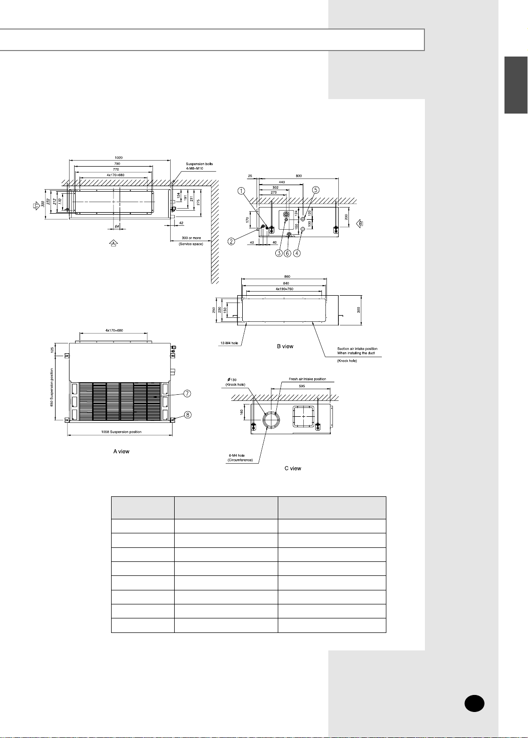
E-7
ENGLISH
Unit : mm
✴✴052/070/072✴✴
1
2
3
4
5
6
7
8
Liquid pipe connection
Gas pipe connection
Drain pipe connection
Interunit wiring port
Power wiring port
Drain pipe connection
Air filter
Hook
ø9.52 Flare
ø15.88 Flare
OD29 ID25
(without drain pump)
OD29 ID25
(with drain pump)
For M8~M10
No.
Name
Description
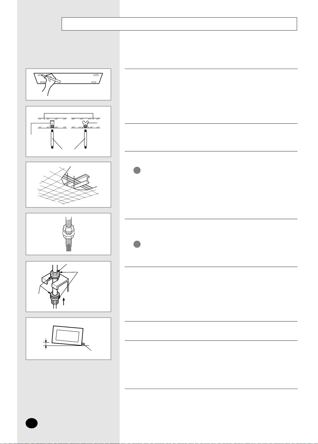
◆ Ensure that the ceiling is strong enough to support
the weight of the indoor unit.
Before hanging the unit, test the strength of each
attached suspension bolt.
◆ If the length of suspension bolt is more than 1.5m,
it is required to prevent vibration.
IMPORTANT
You must install the suspension bolts more than four
when installing the indoor unit.
IMPORTANT
Place the pattern sheet on the ceiling at the spot where you want to install
the indoor unit.
1
Insert bolt anchors. Use existing ceiling supports or construct a suitable
support as shown in figure.
2
Install the suspension bolts depending on the ceiling type.
3
Screw eight nuts to the suspension bolts making space for hanging the
indoor unit.
4
Hang the indoor unit to the suspension bolts between two nuts.
5
Screw the nuts to suspend the unit.
6
Adjust level of the unit by using measurement plate for all 4 sides.
7
◆ Since the diagram is made of paper, it may shrink or stretch
slightly due to temperature or humidity. For this reason, before
drilling the holes maintain the correct dimensions between the
markings; refer to page 6 or 7.
NNNNoooottttee
ee
◆ For proper drainage of condensate, give a 3mm slant to the
drain hose port.
NNNNoooottttee
ee
◆ Piping must be laid and connected inside the ceiling when
suspending the unit. If the ceiling is already constructed, lay
the piping into position for connection to the unit before placing
the unit inside the ceiling.
NNNNoooottttee
ee
Indoor Unit Installation
It is recommended to install the refnet joint before installing the indoor unit.
E-8
Concrete
Suspension bolt(M8)-field supply
Hole in anchor
Hole in plug
Insert
Ceiling support
Drain hose port
3mm
Not supplied
Washer(supplied)
Rubber
Fasten the nut
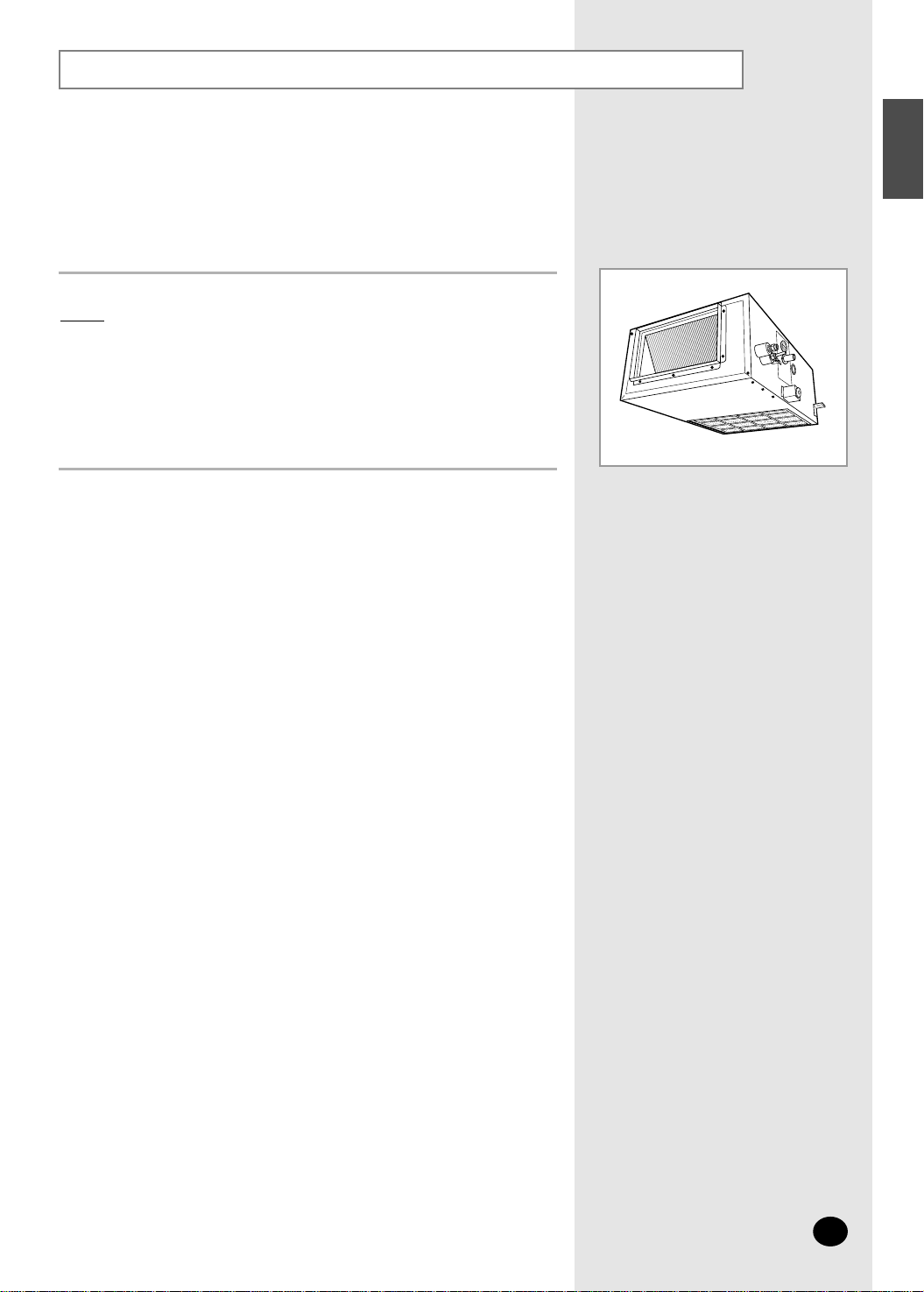
Purging the unit
E-9
ENGLISH
◆
To prevent dirt or foreign objects from getting into the pipes
during installation, do NOT remove the pinch pipe completely
until you are ready to connect the piping.
NNNNoooottttee
ee
On delivery, the indoor unit is loaded with refrigerant gas.
All this gas must therefore be purged before connecting the assembly
piping. To purge the inert gas, proceed as follows.
Unscrew the pinch pipe at the end of each refrigerant pipe.
Result:
All inert gas escapes from the indoor unit.
 Loading...