

Samsung AS18WJWB, AS18WJWD, AS18WJWE, AST18WJWB, AST18WJWE Service Manual
...
ROOM AIR CONDITIONER
INDOOR UNIT
AS18WJWB
AS18WJWD
AS18WJWE
AST18WJWB
AST18WJWE
AS24W6WB
AS24W6WE
AST24W6WB
AST24W6WE
SC18ZWJ
SC24ZW6
SERVICE
OUTDOOR UNIT
US18WJWB
US18WJWD
US18WJWE
UST18WJWB
UST18WJWE
US24W6WB
US24W6WE
UST24W6WB
UST24W6WE
SC18ZWJX
SC24ZW6X
Manual
CONTENTSAIR CONDITIONER
1. Product Specifications
2. Operating Instructions & Installation
3. Disassembly and Reassembly
4. Refrigerating Cycle Diagram
5. Set Up the Model Option
6. Troubleshooting
7. Exploded Views and Parts List
8. Block Diagram
9. Wiring Diagram
1. Product Specifications
1-1 Table
Item
Type
Cooling
BTU/h
Dehumidifying \/h
Air Volume Cooling m3/min
Performance
Noise Cooling dB
Energy Efficiency
BTU/Wh
BTU/Wh
Power ø-V-Hz
Power Consumption kW
Operating Current A
Power
Power Factor Cooling %
Starting Current A
Length m
Power Cord Number of Core Wire
Capacity A
Outer Dimension
Width x Height
x Depth
Weight kg
Refrigerant Pipe
Liquid mm x L(m)
Gas mm x L(m)
Drain Hose D x L(mm)
Size
Compressor
Type
Motor
Type
Rated Output
Oil Type
Type
Blower
Motor
Type
Rated Output W
Heat Exchanger
Refrigerant Control unit
Freezer Oil Capacity cc
Refrigerant to Change(R22) g
Protection Device(OLP)
Cooling Test Condition
Maximum Operation Condition
Model
kcal/h
mm
inch
AS18WJWB
AST18WJWB
AS24W6WB
AST24W6WB
Indoor unit Outdoor unit Indoor unit Outdoor unit
Wall-mounted Wall-mounted
(1)
(2)
4,000 5,050
18,000 24,000
1.9 2.7
13.5 25 14.4 45
45/43/41 58/58 46/44/42 61/61
(1)
(2)
7.05 7.03
9.47 9.60
1-220-60 1-220-60
2.25
1.9
10.1
8.8
(1)
(2)
(1)
(2)
2.85
2.5
13.2
11. 5
(1)
(2)
(1)
(2)
98.0 98.0
47 65
--
--
--
1,065 x 298 x 218 790 x 548 x 285 1,065 x 298 x 218 880 x 638 x 310
41.9 x 11.7 x 8.6 31.1 x 21.6 x 11.2 41.9 x 11.7 x 8.6 34.6 x 25.1 x 12.2
13 39 13 64
ø6.35 x 5 ø6.35 x 5
ø12.7 x 5 ø15.88 x 5
ø18 x 2,000 ø18 x 2,000
Rotary Rotary
Induction Motor(PSC) Induction Motor(PSC)
1,950 2,670
SUNISO-4GSD SUNISO-4GSD
Cross flow Propeller Cross flow Propeller
steel steel steel steel
15 50 15 50
2R0W 16STEP 2ROW 24STEP 2R0W 16STEP 2ROW 28STEP
CAPILLARY TUBE CAPILLARY TUBE
600 800
1,200 1,400
MRA12068-12007 Internal
(1)
INDOOR UNIT : DB29˚C WB19˚C OUTDOOR UNIT : DB46˚C WB24˚C
(2)
INDOOR UNIT : DB27˚C WB19˚C OUTDOOR UNIT : DB35˚C WB24˚C
(2)
INDOOR UNIT : DB32˚C WB23˚C OUTDOOR UNIT : DB54˚C WB24˚C
1Samsung Electronics
Table( cont.)
Item
Type
Cooling
Dehumidifying \/h
Air Volume Cooling m
Perfor-
mance
Noise Cooling dB
Energy Efficiency Cooling
Power ø-V-Hz
Power Consumption Cooling kW
Operating Current Cooling A
Power Factor Cooling %
Power
Starting Current A
Length m
Power Cord Number of Core Wire
Capacity A
Outer Dimension
Weight kg
Refrigerant Pipe
Drain Hose D x L(mm)
Size
Compressor
Oil Type
Blower
Heat Exchanger
Refrigerant Control unit
Freezer Oil Capacity cc
Refrigerant to Change(R22) g
Protection Device(OLP)
Cooling Test Condition
Maximum Operation Condition
Type
Motor
Type
Motor
Width x Height
x Depth
Liquid mm x L(m)
Gas mm x L(m)
Type
Rated Output
Type
Rated Output W
BTU/Wh
Model
kW
BTU/h
3
/min
W/W
mm
inch
AS18WJWD
Indoor unit Outdoor unit
Wall-mounted
5.1
18,000
1.9
13.5 25
45/43/41 58/58
2.76
9.73
1-200/220-50
1.85
8.8
94
42
-
-
-
1,065 x 298 x 218 790 x 548 x 285
41.9 x 11.7 x 8.6 31.1 x 21.6 x 11.2
13 39
ø6.35 x 5
ø12.7 x 5
ø18 x 2,000
Rotary
Induction Motor(PSC)
1,895
SUNISO-4GSD
Cross flow Propeller
steel steel
15 50
2R0W 16STEP 2ROW 24STEP
CAPILLARY TUBE
600
1,200
Internal
NDOOR UNIT : DB27˚C WB19˚C OUTDOOR UNIT : DB35˚C WB24˚C
NDOOR UNIT : DB32˚C WB23˚C OUTDOOR UNIT : DB54˚C WB24˚C
Samsung Electronics2

Table( cont.)
Item
Type
Cooling
Dehumidifying \/h
Air Volume Cooling m
Performance
Noise Cooling dB
Energy Efficiency Cooling
Power ø-V-Hz
Power Consumption Cooling kW
Operating Current Cooling A
Power Factor Cooling %
Starting Current A
Power
Power Cord
Outer Dimension
Weight kg
Refrigerant Pipe
Drain Hose D x L(mm)
Type
Compressor
Size
Oil Type
Blower
Heat Exchanger
Refrigerant Control unit
Freezer Oil Capacity cc
Refrigerant to Change(R22) g
Protection Device(OLP)
Cooling Test Condition
Maximum Operation Condition
Motor
Type
Motor
Length m
Number of Core Wire
Capacity A
Width x Height
x Depth
Liquid mm x L(m)
Gas mm x L(m)
Type
Rated Output
Type
Rated Output W
BTU/Wh
Model
kW
BTU/h
3
/min
W/W
mm
inch
AS18WJWE
AST18WJWE
SC18ZWJ
Indoor unit Outdoor unit Indoor unit Outdoor unit
Wall-mounted Wall-mounted
5.1 6.8
18,000 24,000
1.9 2.7
13.5 25 14.4 45
45/43/41 58/58 46/44/42 61/61
2.62 2.72
9.23 9.60
1-220/240-50 1-220/240-50
1.95 2.5
9.5 12
97 91.4
40 82
--
--
--
1,065 x 298 x 218 790 x 548 x 285 1,065 x 298 x 218 880 x 638 x 310
41.9 x 11.7 x 8.6 31.1 x 21.6 x 11.2 41.9 x 11.7 x 8.6 34.6 x 25.1 x 12.2
13 39 13 64
ø6.35 x 5 ø6.35 x 5
ø12.7 x 5 ø15.88 x 5
ø18 x 2,000 ø18 x 2,000
Rotary Rotary
Induction Motor(PSC) Induction Motor(PSC)
2,120 2,740
SUNISO-4GSD SUNISO-4GSD
Cross flow Propeller Cross flow Propeller
steel steel steel steel
15 50 15 50
2R0W 16STEP 2ROW 24STEP 2R0W 16STEP 2ROW 28STEP
CAPILLARY TUBE CAPILLARY TUBE
600 900
1,100 1,450
Internal Internal
NDOOR UNIT : DB27˚C WB19˚C OUTDOOR UNIT : DB35˚C WB24˚C
NDOOR UNIT : DB32˚C WB23˚C OUTDOOR UNIT : DB54˚C WB24˚C
AS24W6WE
AST24W6WE
SC24ZW6
3Samsung Electronics
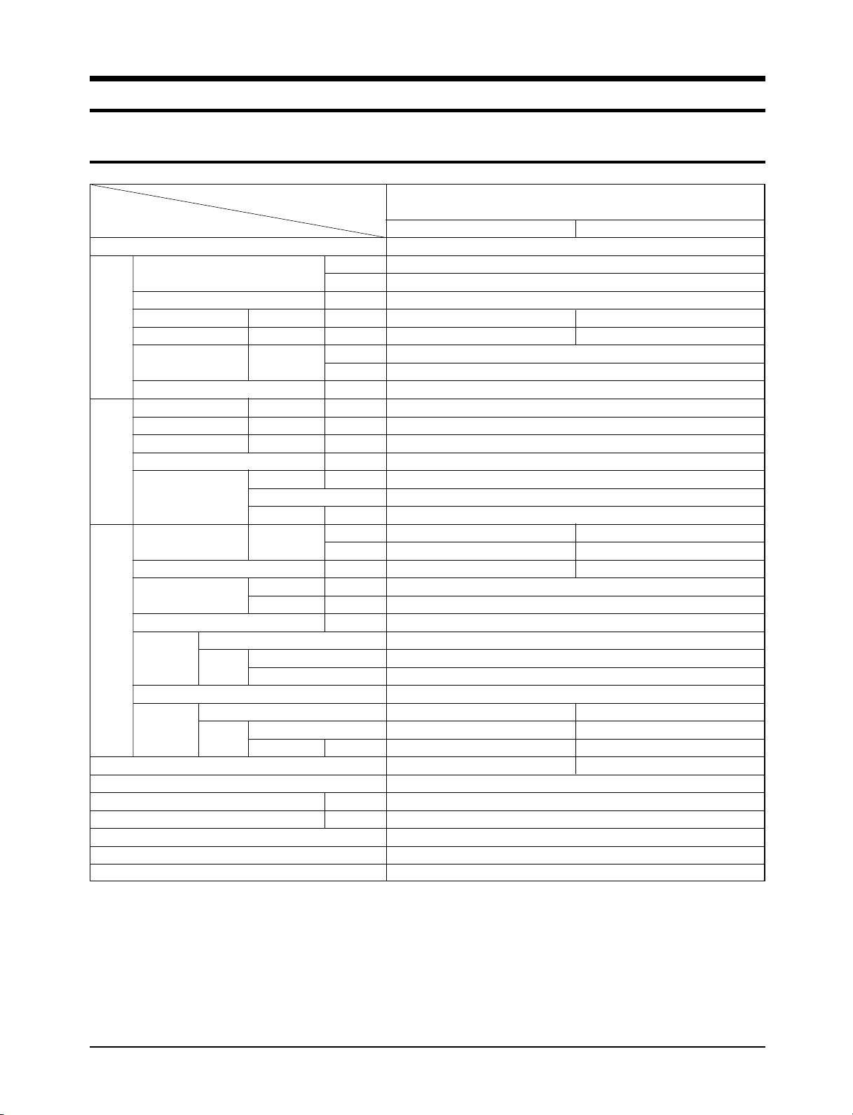
1-2 Pressure Graph
DB32.4 / WB24.0
DB30.6 / WB22.5
DB27.0 / WB19.0
DB24.0 / WB17.0
DB21.0 / WB15.0
Indoor Temp.( C)
Low pressure(kg/cm G)
10
8
6
4
2
0
25.0 35.0 45.0 55.0
Low Pressure Distribution(Cooling mode)
Outdoor Temp.(DB C)
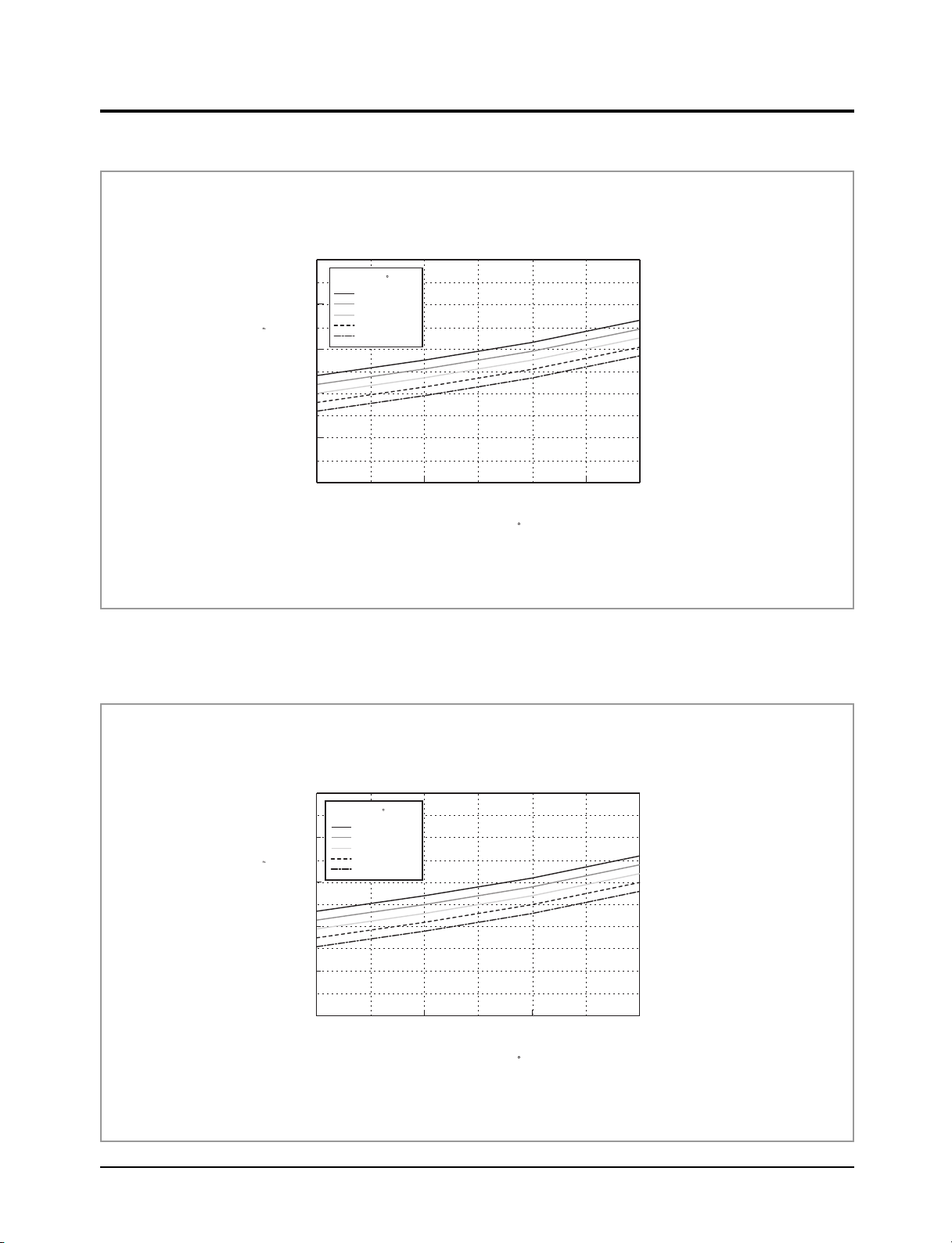
DB32.4 / WB24.0
DB30.6 / WB22.5
DB27.0 / WB19.0
DB24.0 / WB17.0
DB21.0 / WB15.0
Indoor Temp.( C)
Low pressure(kg/cm G)
10
8
6
4
2
0
25.0 35.0 45.0 55.0
Low Pressure Distribution(Cooling mode)
Outdoor Temp.(DB C)
■ 18K BTU
■ 24K BTU
Samsung Electronics4
2. Operating Instructions & Installation
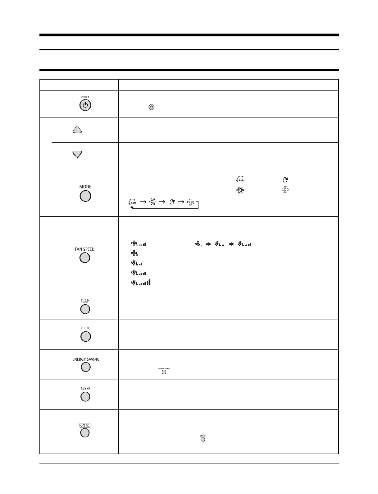
2-1 The Feature of Key in remote control
FUNCTIONBUTTONNo
1
(UP)
On/Off button.
Press the button to stop or run the air conditioner.
Temperature adjustment button(UP).
To increase the temperature by the pressing the temperature button.
2
(DOWN)
3
4
Temperature adjustment button(DOWN).
To decrease the temperature by the pressing the temperature button.
Mode selection button.
Each time you press this button,
Mode is changed in the following order.
Fan speed adjustment button.
Each time you press this button, FAN SPEED is changed in the following order.
Automatic(rotated : )
Low
Medium
High
Turbo(Maximum)
: Auto Mode : Dry Mode
: Cool Mode : Fan Mode
5
6
7
8
9
Flap button.
It adjusts the airflow to upward and downward.
Turbo button.
The air conditioner cools or heats the room as quickly as possible.
After 30minutes, the air conditioner is reset automatically to the previous mode.
Energy saving button.
If you wish to save energy when using your air conditioner, select the Energy saving
mode with the button.
Sleep button.
The sleep timer can be used when you are cooling or heating your room to switch the air conditioner
off automatically after a period of 6 hours.
On Timer button.
The On Timer enables you to switch on the air conditioner automatically after
a given period of time that is from 1 hour to 24 hours.
To set the operating time, press the button one or more times until the required
time display.
5Samsung Electronics
Operating Instructions & Installation
10
11
12
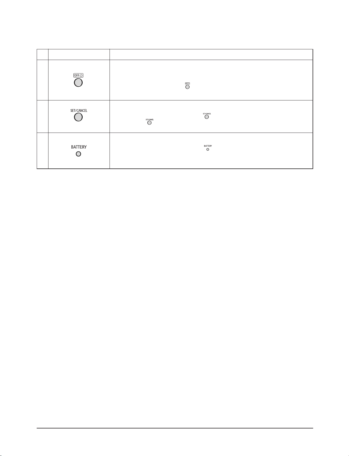
FUNCTIONBUTTONNo
Off Timer button.
The Off Timer enables you to switch off the air conditioner automatically after
a given period of time that is from 1 hour to 24 hours.
To set the operating time, press the button one or more times until the required
time display.
Timer Set/Cancel button.
After setting On Timer or Off Timer, press the button to set it completely.
And press the button again to cancel On Timer or Off Timer set.
Battery life indicator.
If you want to check the battery life, press the button.
The longer will remain the battery life.
If one battery life indicator remains, replace new batteries.
Samsung Electronics6
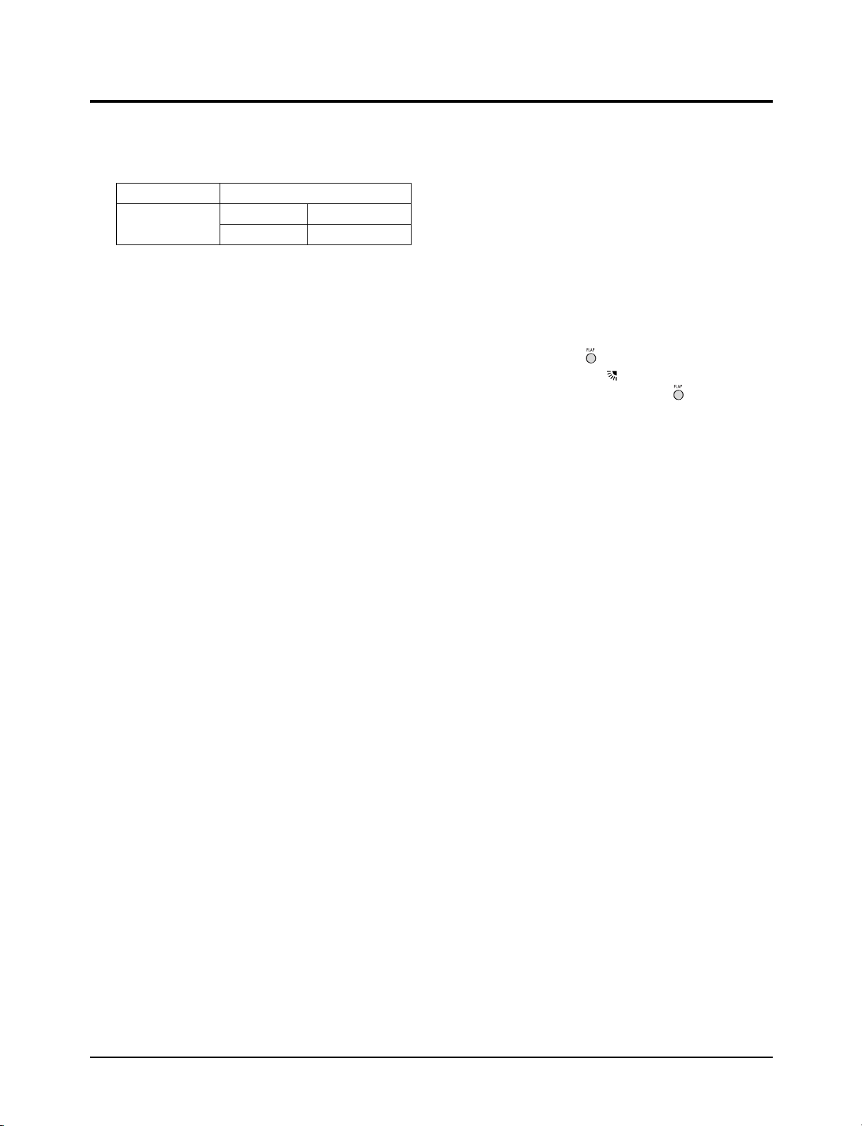
2-2 Details for Operation Property
1. AUTO MODE : In this mode, operation COOL mode is
selected automatically by the difference between the
setting and room temperature.
Operation Type Room Temp.
Cool Operation
Ts : Setting temperature.
2. COOL MODE : The unit operates according to the
difference between the setting and room temperature.
(16°C~30°C)
3. DRY MODE : Has 4 states, each determined by room
temperature.
The unit operates in DRY mode.
*Compressor ON/OFF time is controlled compulsorily
(can not set up the fan speed, always breeze).
*Protective function : Low temperature release.
(Prevention against freeze)
4. TURBO MODE : This mode is available in AUTO, COOL,
DRY, FAN MODE.
When this button is pressed at first, the air conditioner is
operated "powerful" state for 30 minutes regardless of the
setting temperature, room temperature.
When this button is pressed again, or when the operating
time is 30 minutes, turbo operation mode is canceled and
returned to the previous mode.
*But, if you press the TURBO button in DRY or FAN
mode that is changed with AUTO mode automatically.
Tr ≥ Ts+1.0°C Compressor ON
Tr ≤ Ts Compressor OFF
6. FAN SPEED : Fan speed automatically varies depending
on both the difference between setting and the room temperature.
Can set up the fan speed in COOL,FAN mode.
7. COMPULSORY OPERATION :
For operating the air conditioner without the remote
control.
*The operating is the same function that AUTO MODE in
the remote control.
8. FLAP : BLADE-H is rotated vertically by the stepping
motor.
*Flap Set : Press the button under the remote control
is displayed on LCD the and the blades move up and
down. If the one more time press the button, blades
location is stop.
9. SETTING THE ON/OFF TIMER. :
*ON TIMER : The On Timer enables you to switch on the
air conditioner automatically after a given period of time.
You can set the period of time from 1 hour to 24 hours.
*OFF TIMER : The Off Timer enables you to switch off
the air conditioner automatically after a given period of
time. You can set the period of time from 1 hour to 24
hours.
10. BUZZER SOUND : Whenever the On/Off button is
pressed or whenever change occurs to the condition
which is set up or select, the compulsory operation mode,
buzzer is sounded "beep".
5. SLEEP MODE : Sleep mode is available only in COOL
mode.
The operation will stop after 6 hours.
*In COOL mode : The setting temperature is automatical-
ly raised by 1°C each 1hour When the temperature has
been raised by total of 2°C, that temperature is
maintained.
7Samsung Electronics
2-3 Installation
D
A
2-3-1 Before Installation
Keep the air conditioner drain hose outlet and inlet free from its surroundings.
In case of breakdown, keep the symmetry and fix it to prevent vibration.
The pipe length shall meet the standard as far as possible.
2-3-2 Installation Procedure
■ Location
Install the product in an area to guarantee the best cooling effect, convenience of piping and electric work, and inexistence of
vibration or wind in the vicinity.
■ Wall Drilling
Drill the wall downward in a diameter of 60 to 65mm.
■ Fixing Indoor Unit & Outdoor Unit
Fix the air conditioner hard enough so that it can not fall to the ground. On the roadside, the outdoor unit shall be installed 2m
above ground and kept away from pedestrians to prevent direct exposure to hot wind.
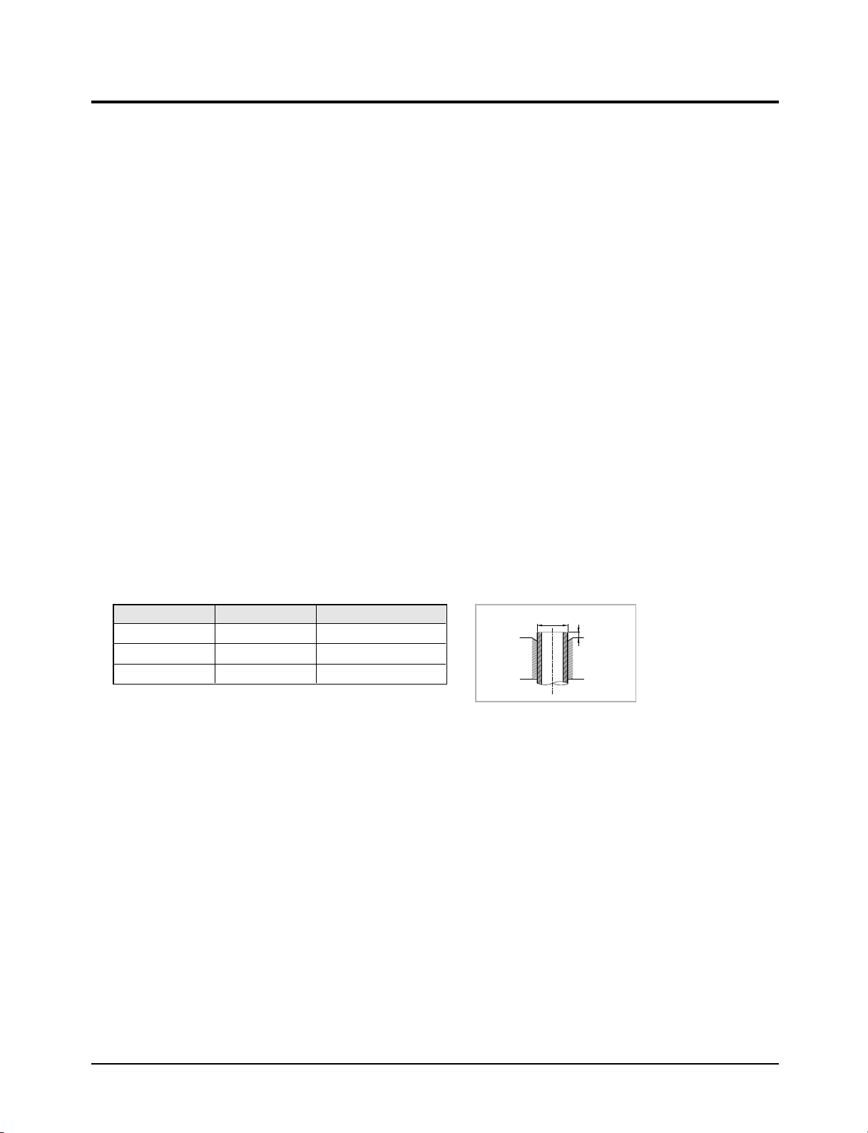
■ Pipe Spooling & Connecting
You shall cut the pipe straightly with a pipe cutter and grind all the burrs of the cut surface.
Pipe expansion may continue until the pipe surface becomes uneven or torn apart.
Be sure to use a torque wrench to tighten pipes or flare nuts.
<Torque & Depth>
Outer Diameter(D)
6.35mm(1/4")
12.70mm(1/2")
15.88mm(5/8")
Torque
140~170
380~420
440~480
(kgf.cm)
Depth
1.3mm
2.0mm
2.2mm
(A)
■ Leak Test
Put an inert gas like nitrogen in the outdoor unit pipe and put soap bubbles or other test liquids on the pipe surface for the leak test.
■ Drain Hose Connecting
Install the drain hose downward to drain water naturally. Be sure to pour water into the hose to check if it drains well.
■ Electric & Earth Work
Electric and earth work shall meet the "Electric Facility Technology Standard" and the "Internal Wire Regulation" of the Electric
Business Laws.
■ Inspection & Trial Run
Upon completion of the tests, you shall make a trial run while you explain the main functions of the air conditioner to finish the
installation.
Samsung Electronics8

2-4 Installation Diagram of Indoor Unit and Outdoor Unit
2-4-1 Air-Purge Procedure
1) Connect each assembly pipe to the appropriate
valve on the outdoor unit and tighten the flare nut.
2) Connect the charging hose of low pressure side
of manifold gauge to the packed valve having a
service port (3/8" Packed valve) as shown at the
figure.
3) Open the valve of the low pressure side of
manifold gauge counter-clockwise.
4) Purge the air from the system using vacuum
pump for about 30 minutes.
- After that, please recheck that pressure is
stabilization.
- Close the valve of the low pressure side of
manifold gauge clockwise.
- Remove the hose of the low pressure side
of manifold gauge.
Outdoor unit
Indoor unit
A
B
Gas pipe side
Liquid pipe side
C
D
5) Set valve cork of both liquid side and gas side of
packed valve to the open position.
6) Mount the valve stem nuts to the 2-Way and
3-Way valve. And mount the service port cap to
3-Way valve.
7) Check for gas leakage.
- At this time, especially check for gas
leakage from the 3-Way valve’s stem nuts,
and from the service port cap.
A
(gas)
B
(liquid)
Valve stem
Vacuum Pump
Stem cap
9Samsung Electronics

Operating Instructions & Installation
R22
2-4-2 Refrigerant Refill(R22)
Refill an air conditioner with refrigerant when refrigerant has been leaked at installing or using.
1) Purge air(for new installation only).
2) Turn the 3-Way valve clockwise to close,
connect the pressure gauge (low pressure side)
to the service valve, and open the 3-Way valve
again.
3) Connect the tank to refill with refrigerant.
4) Set the unit to cool operation mode.
5) Check the pressure indicated by the pressure
gauge(low pressure side).
* Standard pressure is should be 4.5~5.5kg/cm
in a regular, high operation mode.
2
6) Open the refrigerant tank and fill with refrigerant
until the rated pressure is reached.
* It is recommended not to pour the refrigerant
in too quickly, but gradually while operating a
pressure valve.
Compound
gauge
For mounting
other and of
hose when
not in use
Suspension hook
High
pressure
gauge
Hand
wheel
Finger tight
fittings
Connected to
high pressure
side
Charging line
7) Stop operation of the air conditioner.
8) Close the 3-Way valve, disconnect the
pressure gauge, and open the 3-Way valve
again.
9) Close the cap of each valve.
Samsung Electronics10

Operating Instructions & Installation
2-4-3 "Pump down" Procedure
Pump down will be carried out when an evaporator is replaced or when the unit is relocated in another area.
1) Remove the caps from the 2-Way valve and the
3-Way valve.
2) Turn the 3-Way valve clockwise to close and
connect a pressure gauge (low pressure side)
to the service valve, and open the 3-Way valve
again.
3) Set the unit to cool operation mode.
(Check if the compressor is operating.)
3-Way Valve
2-Way Valve
4) Turn the 2-Way valve clockwise to close.
5) When the pressure gauge indicates "0" turn the
3-Way valve clockwise to close.
6) Stop operation of the air conditioner.
7) Close the cap of each valve.
Relocation of the air conditioner
• Refer to this procedure when the unit is relocated.
• Carry out the pump down procedure (refer to the details of 'pump down').
• Remove the power cord.
• Disconnect the assembly cable from the indoor and outdoor units.
• Remove the flare nut connecting the indoor unit and the pipe.
• At this time, cover the pipe of the indoor unit and the other pipe using a cap or vinyl plug to avoid foreign
material entering.
• Disconnect the pipe connected to the outdoor unit.
At this time, cover the valve of the outdoor unit and the other pipe using a cap or vinyl plug to avoid foreign
material entering.
• Make sure you do not bend the connection pipes in the middle and store together with the cables.
• Move the indoor and outdoor units to a new location.
• Remove the mounting plate for the indoor unit and move it to a new location.
11Samsung Electronics

3. Disassembly and Reassembly
Stop operation of the air conditioner and remove the power cord before repairing the unit.
3-1 Indoor Unit
No Parts Procedure Remark
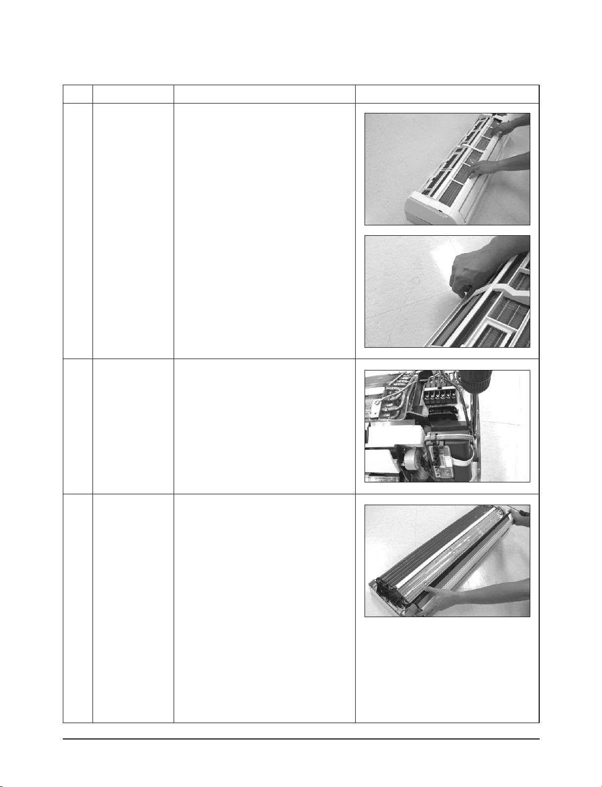
1 Front Grille
1) Stop the air conditioner operation and
shut off the main power.
2) Open the Front Grille by pulling right and
left sides of the hook.
3) Loosen 1 of the right screw and detach
the Terminal Cover.
4) Detach the thermistor from the Front
Grille.
5) Loosen 3 fixing screws of Front Grille.
Samsung Electronics12
Disassembly and Reassembly
No Parts Procedure Remark
6) Unlock 3 hooks to fix Panel Front and
Tray Drain.
7) Unlock 3 hooks to fix Panel Front and
Back-Body.
2
3
Control-In
(Main PCB)
Tray Drain
1) Take all the connector of PCB upper side
out. (Inclusion Power Cord)
2) Detach the outdoor unit connection wire
from the Terminal Block.
3) Loosen 4 fixing screws of Ass'y Control-In.
1) Pull Tray Drain out from the Back Body.
13Samsung Electronics
Disassembly and Reassembly
No Parts Procedure Remark
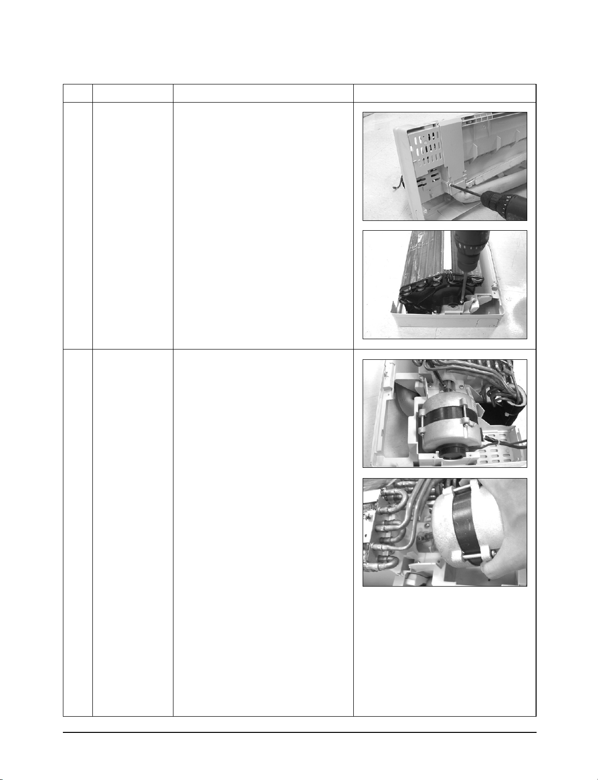
4
5
Heat Exchanger
Fan Motor
&
Cross Fan
1) Loosen 2 fixing earth screws of right side.
2) Detach the Connection Pipe.
3) Detach the Holder Pipe at the rear side.
4) Loosen the 4 fixing screws of right and left
side.
5) Lifting the Heat Exchanger up a little to
push the up side for separation from the
indoor unit.
1) Loosen the fixing screw.
2) Detach the Fan Motor from the Fan.
3) Detach the Fan From the left Holder
Bearing.
Samsung Electronics14
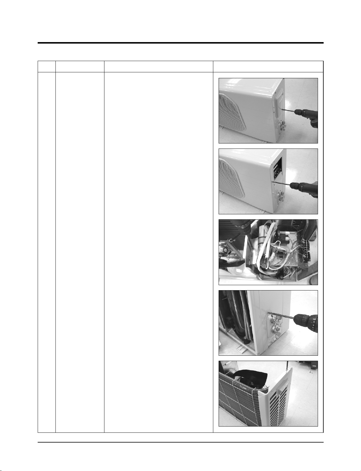
3-2 Outdoor Unit
■ 18K BTU
No Parts Procedure Remark
1 Common Work
1) Loosen the fixing screw of the
Cover Control.
2) Loosen the fixing screws on right and left,
back Cabinet-Side edge and a fixing screw
on the Cabinet-Front lower to detach the
Cabinet-Front.
3) Loosen the fixing screws of the
Ass'y-Control Out.
4) Loosen the fixing screws of the
Cabinet-Side RH.
5) Loosen the fixing screws of the
Cabinet-Side LF.
15Samsung Electronics
Disassembly and Reassembly
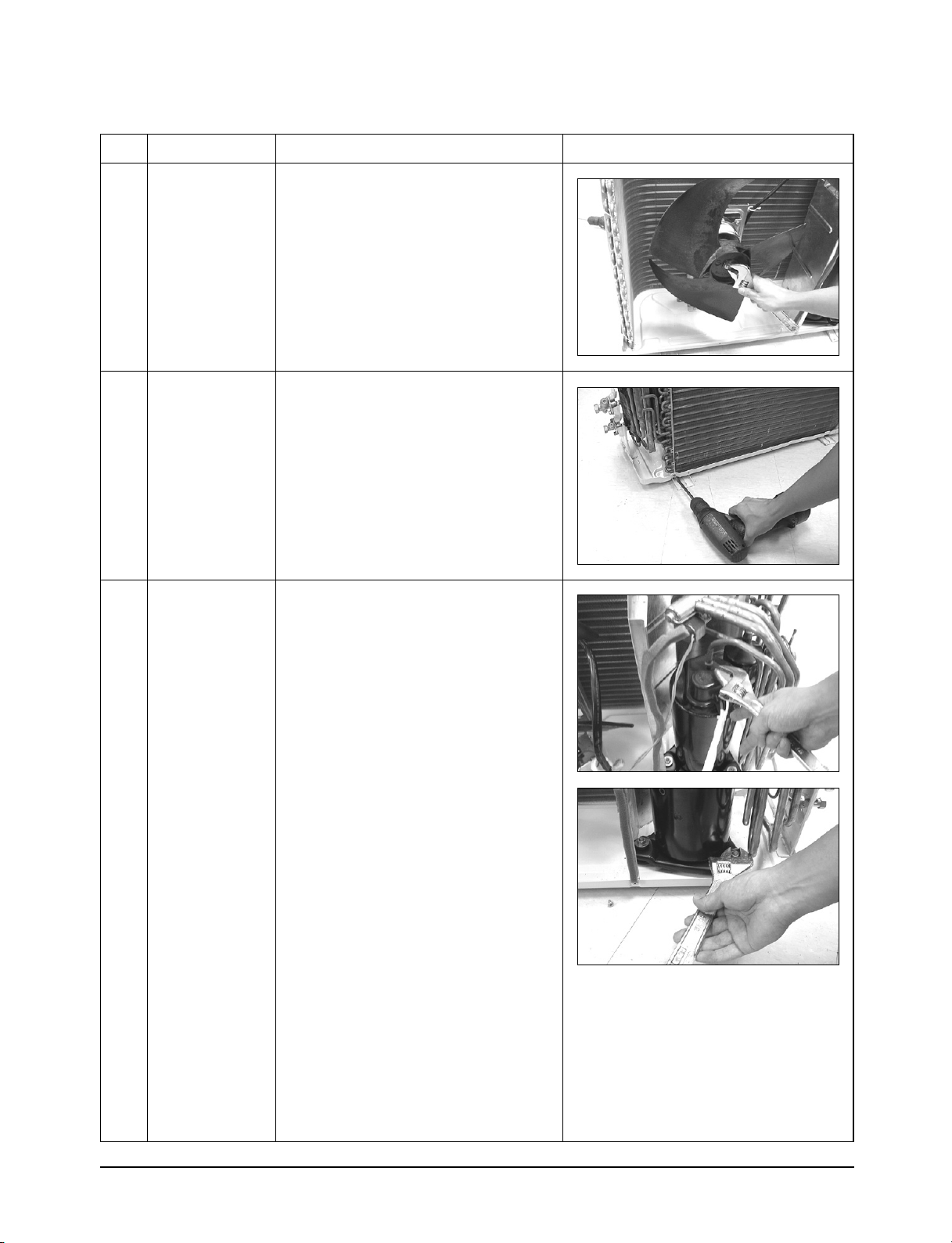
No Parts Procedure Remark
2
3
4
Fan & Motor
Heat Exchanger
Compressor
1) Detach the Nut Flange.(Turn counterclockwise because the screw is right-handed)
2) Detach the Fan.
3) Loosen 4 fixing screws to detach
the Motor.
1) Loosen 3 fixing screws of the Bar Steel.
2) Loosen 2 fixing screws on both sides.
3) Disassemble the pipe in both inlet and
outlet with welding torch.
4) Detach the Heat Exchanger.
1) Loosen the Terminal Cover nut to open the
Terminal Cover.
2) Disassemble the cloth sound felt.
3) Disassemble the pipe in both inlet and
outlet of the Compressor with welding
torch.
4) Loosen the 3 bolts at the bottom.
5) Detach the Compressor.
Samsung Electronics16
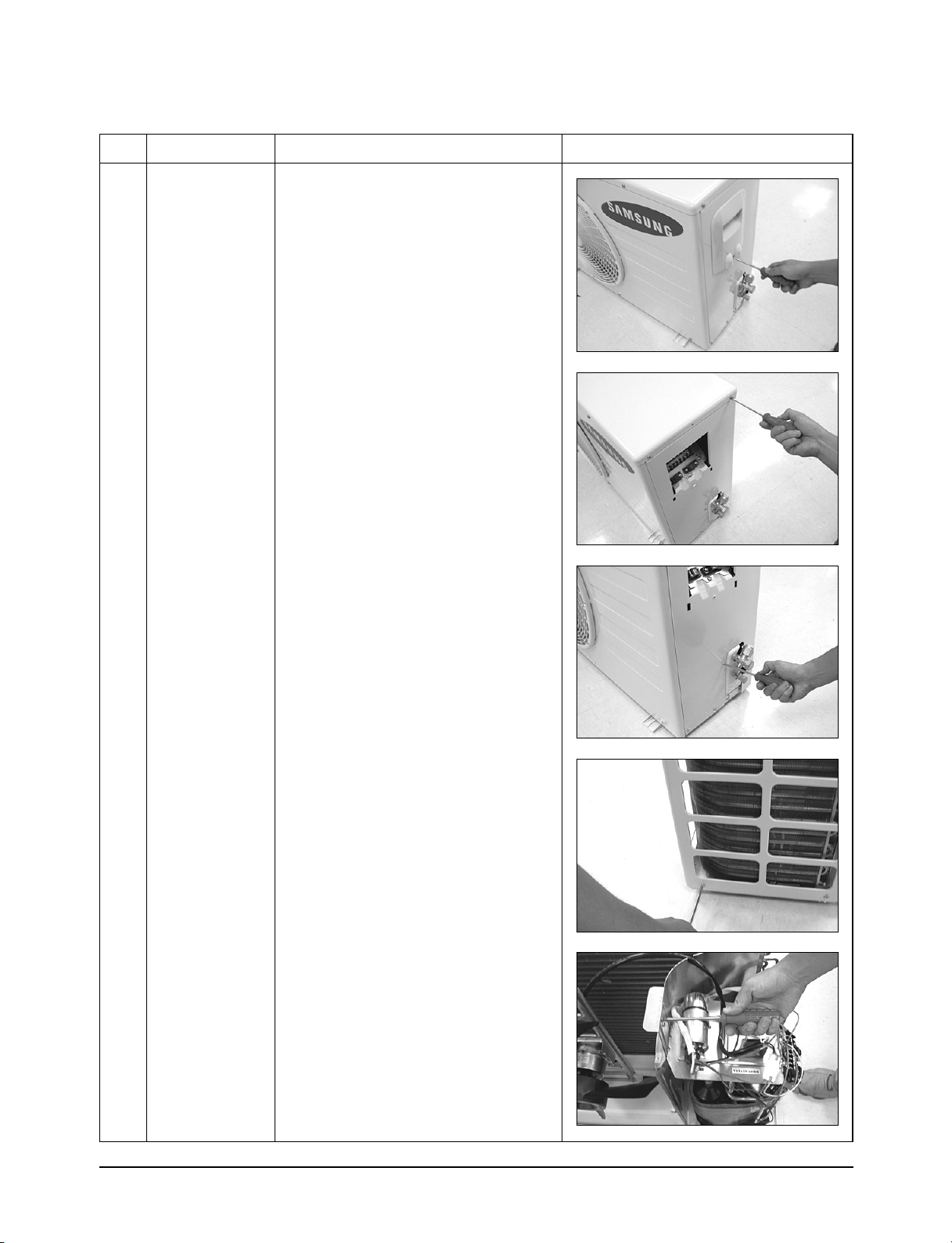
■ 24K BTU
No Parts Procedure Remark
Disassembly and Reassembly
1 Common Work
1) Loosen the fixing screw of the Cover
Control.
2) Loosen the fixing screws of the
Cabinet-Upper.
3) Loosen the fixing screws of the
Cabinet-Side RH.
4) Loosen the fixing screws of the
Cabinet-Side LF.
5) Loosen the fixing screws of the
Ass'y Control Out.
17Samsung Electronics
 Loading...