

SAMSUNG AS18A1UE Service Manual
ROOM AIR CONDITIONER
AS180UE
AS181UE
AS18A1UD
AS18A1UE
AS-2408BR
SERVICE
Manual
CONTENTSAIR CONDITIONER
1. Pre c a u t i o n s
2. Product Specifications
3. Operating Instructions and
I n s t a l l a t i o n
4. Disassembly and Reassembly
5. Tro u b l e s h o o t i n g
6. Exploded Views and Parts List
7. Block Diagrams
8. PCB Diagrams
9. Wiring Diagrams
10. Schematic Diagrams

© Samsung Electronics Co., Ltd. FEB. 1999.
Printed in Korea.
Code No. DB81-10161A(3)
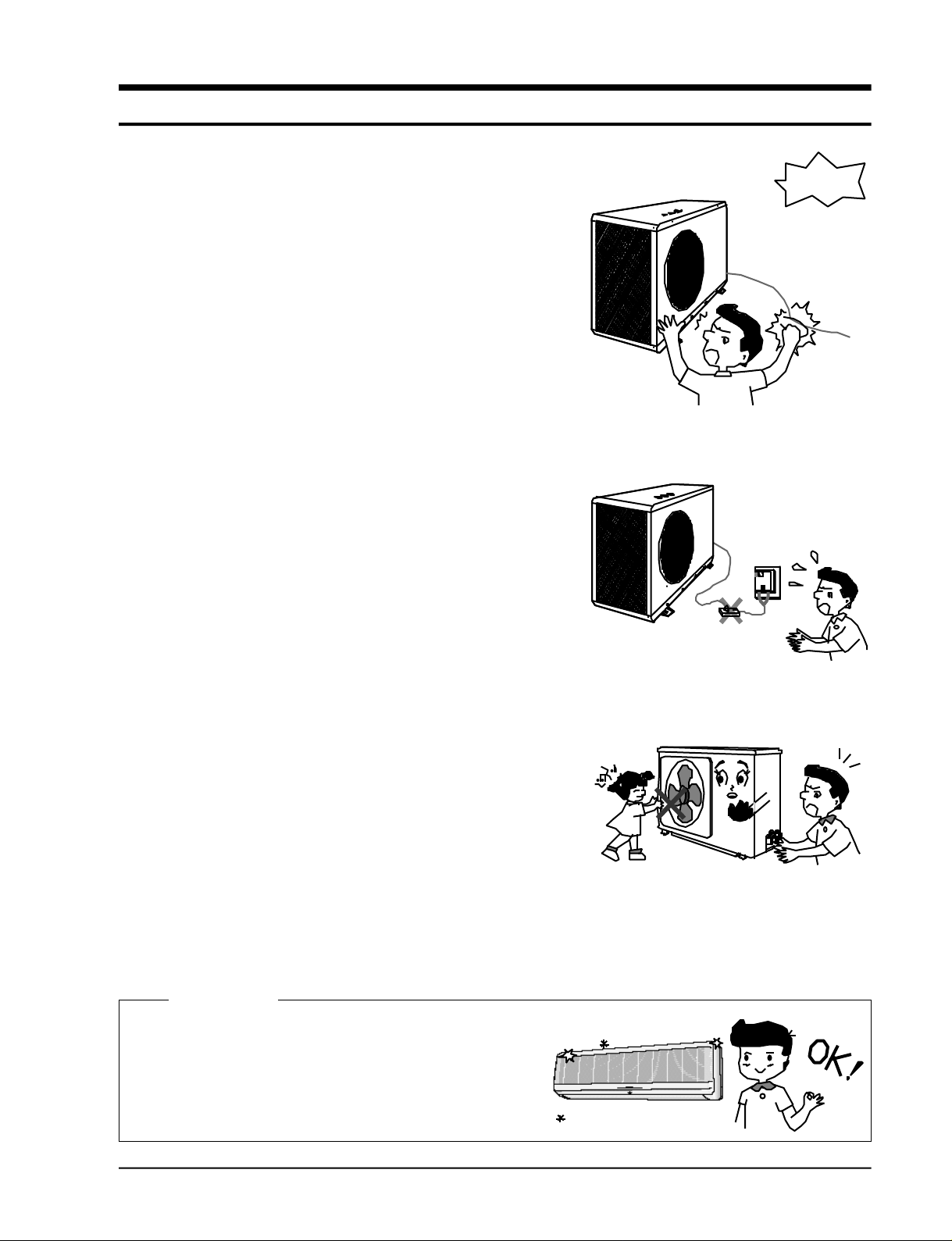
1. Precautions
1) Remove power cable from power outlet.
Remove power cable from an outlet prior to disassembly for
repair.
When the power cable is removed wait for at least 1 minute
and measure the voltage between the + and - terminal of the
large capacity electrolyti capacitor using a tester. Make sure
that the voltage is less than DC 10V, then starts repairing.
2) Warning about electrical shock
If you cannot avoid checking the circuits with power not
disconnected pay special attention not to touch live parts to
avoid electric shock.
3) Use proper parts
Use genuine parts of a model if parts need to be replaced.
(It is recommended that parts are replaced rather than
repaired, to avoid electrical contact. Customers should
refrain from repairing parts themselves as this can be
extremely dangerous.)
4) Use proper tools
Use proper tools for repair and be familiarized with
handling test equipment.
Using worn out tools may result in problems such as
intermittent contact, etc.
dangerous
5) Lead wire or power cable damaged
Check if lead wire or power cord is damaged prior to repair,
and replace if damaged.
6) Avoid tapping a power cord
Tapping a power cable or using an extension cord from a
power outlet is dangerous and should be avoided. It may
result is malfunctioning or fire.
7) Checking insulation
Be sure to check insulation resistance when assembly is
completed. (Check insulation resistance between the power
cord plug and ground terminal using an ohm meter and
check if it is greater than 30MΩ prior to applying the power.)
8) Check grounding
Check grounding status and fix it if not sufficient.
9) Check installation condition
Check installation condition and fix insufficient conditions.
If it is still not satisfactory find another area for installation.
10) Child care
It is recommended to have children stay away the units
when the repair is being done to avoid accidents.
Cleaning
No
inter connection
Brilliantly
Clean the unit and the area arount it.
Let the customer know that the unit has been repaired.
Samsung Electronics
1-1

M E M O
1-2
Samsung Electronics
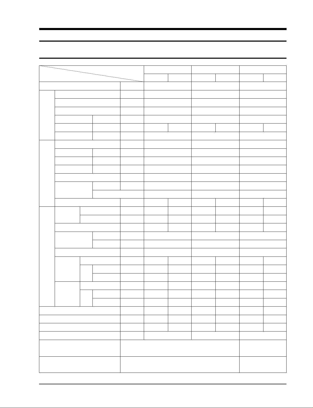
2. Product Specifications
2-1 AS180UE/AS181UE/AS18A1UE/AS18A1UD/AS-2408BR
I t e m
Ty p e C o o l i n g B T U / h
D e h u m i d i t y i n g l/ h
P e rf o rm a n c e
P o w e r
E l e c t r i c a l
C h a r a c t e r i st i c s
P ro d u c t
Maximum operation Condition
“*” : Tailand Only
Low temp. heating B T U / h
Air volume C o o l i n g m3/ m i n
N o i s e C o o l i n g d B
E n e rgy efficiency ratio C o o l i n g B T U / h . W
Power V- H z
Power Consumption C o o l i n g W
Operating Curre n t C o o l i n g A
Power factor C o o l i n g %
S t a rting curre n t A
Power cable L e n g t h m
Number of core wire
Fuse capacity A
Outer Width x Height m m
dimension x Depth i n c h
We i g h t k g
Coolant pipe L i q u i d OD(mm) x L(m)
C o o l a n t OD(mm) x L(m)
Drain hose ID(mm)x L(m)
C o m p ressor Ty p e
M o t o r Ty p e
Rated input W
Blower Ty p e
M o t o r Ty p e
Rated input W
Heat exchanger
Coolant control unit
F reezer oil capacity c c
Coolant to charg e ( R - 2 2 ) g
Cooling test Condition
M o d e l
A S 1 8 0 U E / A S 1 8 1 U E / A S 1 8 A 1 U E
Indoor unit Outdoor unit
Wa l l - m o u n t i n g
1 7 , 5 0 0 ( * 1 7 , 0 0 0 )
1 . 6
-
1 3 . 8
4 5 5 5
9 . 7 ( * 9 . 4 )
1-220 / 240-50
1 8 0 0
8 . 0
93.8 (at 240V)
4 0
6 . 2
3G x 2.5mm2/ A re a
3 . 1 5 1 0 5 0 x 2 9 8 x 1 8 0 7 8 7 x 6 2 0 x 3 2 0
4 1 . 3 4 x 1 1 . 7 3 x 7 . 0 9 3 0 . 9 8 x 2 4 . 4 x 1 2 . 6
1 3 4 6
ø6.35 x 5
ø12.7 x 5
ø17 x 2
- R o t a ry
- -
- 1 8 5 5
C ro s s - f a n P ro p e l l e r
R e s i n S t e e l
3 0 6 0
2Row 12Step 2Row 24Step
C A P I L L A RY TUBE
6 0 0
1 , 5 8 0
INDOOR UNIT : DB 27°C W B 1 9 ° C
OUTDOOR UNIT : DB35°C W B 2 4 ° C
INDOOR UNIT : DB 32°C W B 2 3 ° C
OUTDOOR UNIT : DB 43°C W B 2 6 ° C
AS18A1UD
Indoor unit Outdoor unit
Wa l l - m o u n t i n g
17,000 (5,000W)
4 5 5 5
1-200 / 220-50
3G x 2.5mm2/ A re a
3 . 1 5 1 0 5 0 x 2 9 8 x 1 8 0 7 8 7 x 6 2 0 x 3 2 0
4 1 . 3 4 x 1 1 . 7 3 x 7 . 0 9 3 0 . 9 8 x 2 4 . 4 x 1 2 . 6
1 3 4 6
- R o t a ry
- -
- 1 8 5 5
C ro s s - f a n P ro p e l l e r
R e s i n S t e e l
3 0 6 0
2Row 12Step 2Row 24Step
1 . 6
-
1 3 . 8
9 . 2
1 8 5 0
9 . 3
90.9 (at 220V)
4 0
6 . 2
ø6.35 x 5
ø12.7 x 5
ø17 x 2
C A P I L L A RY TUBE
1 , 1 8 0
AS-2408BR
Indoor unit Outdoor unit
Wa l l - m o u n t i n g
4 6 5 6
1 - 2 2 0 - 6 0
3G, AW G 1 4
3 . 1 5 1 0 5 0 x 2 9 8 x 1 8 0 7 8 7 x 6 2 0 x 3 2 0
4 1 . 3 4 x 1 1 . 7 3 x 7 . 0 9 3 0 . 9 8 x 2 4 . 4 x 1 2 . 6
1 3 4 6
ø6.35 x 5
ø15.8 x 5
- R o t a ry
- -
- 2 1 5 7
C ro s s - f a n P ro p e l l e r
R e s i n S t e e l
3 0 6 0
2Row 12Step 2Row 24Step
6 0 0
INDOOR UNIT : DB 27°C W B 1 9 . 5 ° C
OUTDOOR UNIT : DB35°C W B 2 4 ° C
INDOOR UNIT : DB 32°C W B 2 2 . 5 ° C
OUTDOOR UNIT: DB 43°C W B 2 5 . 5 ° C
2 2 , 0 0 0
2 . 8
-
1 4 . 3
1 0 . 5
2 1 0 0
1 0 . 0
9 5 . 4
5 0
6 . 2
ø17 x 2
C A P I L L A RY TUBE
6 0 0
1 , 6 5 0
Samsung Electronics
2-1
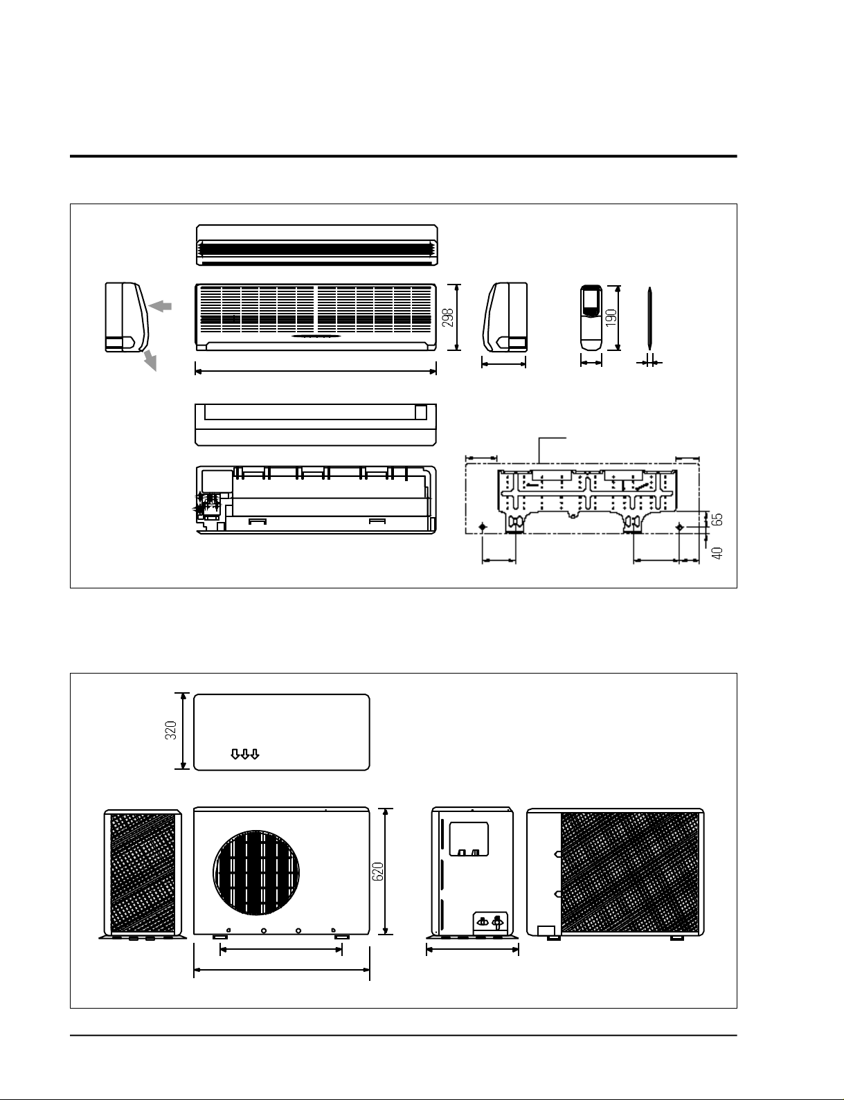
2-2 Dimensions
2-2-1 Indoor Unit
Air out
(Front view)
Air
in
(Rear view)
1050
unit : mm
(Remote control unit)
180 63
21
(Installation plate)
outer edge of
250 145
260 200 100
indoor unit
2-2-1 Outdoor Unit
2-2
(Front view) (Rear view)
582 340
787
Samsung Electronics
3. Operating Instructions and Installation
3-1 Operating Instructions
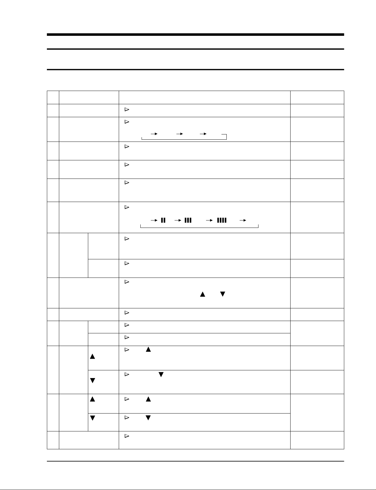
3-1-1 Name & Function of Key in remote controller
NO
NAMED OF KEY
1
2
3
4
5
6
7
FAN SPEED
SWING
ON/OFF
MODE
TURBO
MILD
Q. TIMER
SET
AUTO
Use this button to start and stop air conditioner.
Each time you press this button,
MODE is changed in the following order.
"AUTO" "COOL" "DRY" "FAN"
Use this button to provide heavy duty cooling
for 30 minutes.
Use this button to provide pleasant cooling
for 3 hours.
Set up the reserve or cancel the timer on and timer off quickly.
Each time you press this button,
FAN SPEED is changed in the following order.
"AUTO" " (L)" " (ME)" " (HI)" NATURAL
Adjusts air flow vertically.
Each time you press this button,
BLADE-H rotates by 8° (Changable range 50°).
Each time you press this button,
BLADE-H rotates within 35° and stop.
FUNCTION OF KEY
ONE SHOT KEY
ONE SHOT KEY
OR
CONTINUOUS KEY
ONE SHOT KEY
ONE SHOT KEY
ONE SHOT KEY
OR
CONTINUOUS KEY
ONE SHOT KEY
OR
CONTINUOUS KEY
ONE SHOT KEY
OR
CONTINUOUS KEY
ONE SHOT KEY
10
12
11
13
8
9
TIME
TIMER/CANCEL
TIMER
TIME
TEMP
SLEEP
ON
OFF
(UP)
(DOWN)
(UP)
(DOWN)
Without regard to ON/OFF condition in remote controller,
use this button to set current time.
Adjust the current time using TIME button.
(Data can be transmitted after setting up the time)
Use this button to reserve or cancel the timer on and timer off.
Set up the time that operation start.
Set up the time that operation stop.
If the TIME button is pressed once, the time increase by one
minute during the time set mode, and ten minutes during the
timer set mode.
If the TIME button is pressed once, the time decrease by one
minute during the time set mode, and ten minutes during the
timer set mode.
If the button is pressed once,
the setting temperature is increased by 1°C.
If the button is pressed once,
the setting temperature is decreased by 1°C.
Use this button for sleep operation.
(The SLEEP mode can be selected at COOL mode.
ONE SHOT KEY
ONE SHOT KEY
ONE SHOT KEY
ONE SHOT KEY
OR
CONTINUOUS KEY
ONE SHOT KEY
OR
CONTINUOUS KEY
ONE SHOT KEY
OR
CONTINUOUS KEY
ONE SHOT KEY
Samsung Electronics
3-1

Operating Instructions and Installation
3-1-2 Main controller function.
1. A U TO MODE: In this mode, operation
mode (COOL) is selected automatically by
the room temperature of initial operation.
Operation Type
Cool Operation (Set Temp:24°C + ∆T)
∆T= -1°, -2°C, 0°C, +1°C, +2°C
∆T is controlled by setting temperature
up/down key of remote contro l l e r
2. C O O L MODE: The unit operates accord i n g
to the diff e rence between the setting and
room temperature .
The setting temperature range is
1 8 ° C t h rough 30°C.
3. D RY MODE: The unit is operated at comp ressor on state re g a rdless of room tempera t u re for an initial 30 minutes of dehumidification operation, and the indoor fan motor
is automatically operated due to the tempera t u re diff e rence between the room temperat u re and set temperature .
The compressor is automatically contro l l e d
due to the temperature diff e rence between
room temperature and set temperature after
operation of 30 minutes.
* Set temperature: 18°C~30°C
* Protective function: Low temperature
release. (Prevention against fre e z e )
4. TURBO MODE: This mode is available only
in A U TO, COOL m o d e .
When this button is pressed at first, the air
conditioner is operated “powerful” state for
30 minutes re g a rdless of the set temperat u re, room temperature .
When this button is pressed again, or when
the operating time is 30 minutes, turbo
operation mode is canceled and returned to
the previous mode.
5 . MILD MODE: This mode is available only
in A U TO, COOL m o d e .
When this button is pressed at first, the air
conditioner is operated in its current state
for 3 hours.
The setting temperature is automatically
raised by 3°C.
When this button is pressed again or when
the operating time is 3 hours, mild operation mode is canceled and returned to the
p revious mode.
6 . S L E E P MODE: Sleep mode is available only
in COOL m o d e .
The operation will stop after 6 hours.
* In COOL mode : The setting temperature
is automatically raised by 1°C each 1hour
When the temperature has been raised by
total of 2°C, that temperature is maint a i n e d .
7. FAN SPEED: Manual (3 step), Auto (4 step),
N a t u r a l
Fan speed automatically varies depending
on both the diff e rence between setting and
the room temperature .
8 . C O M P U L S O RY O P E R ATION:
For operating the air conditioner without
the remote contro l l e r.
The operating is the same function that
A U TO MODE in the remote contro l l e r.
* Set temperature: 22°C
3-2
Samsung Electronics

Operating Instructions and Installation
9 . SWING: BLADE-H is rotated vertically by
the stepping motor.
* Memory louve: When ON/OFF button is
p ressed at stop state, the BLADE-H re t u r n s
to its original location which is operating
state before stop.
* Swing auto: The BLADE-H can ro t a t e
within about 35° in the original position set
by the SWING SET button.
* Swing set: Press the SWING SET button,
then the blade rotates vertically by 8°
The BLADE-H location is dispalyed on
REMOTE CONTROL. (total 7 steps)
1 0 . Q.TIMER: Q. timer (quick timer) allows
reservation or cancel the timer on and timer
o ff quickly.
When Q.timer button is pressed at operating state, LCD displays the polling state
s e q u e n t i a l l y.
The LCD also displays the time re m a i n i n g .
1 2 . SELF TEST
* Interruption of electric power and Power
o n .
* Abnormal condition of the room sensor.
* Indoor unit fan motor lock.
* Abnormal condition of the indoor unit's
heat exchanger sensor.
1 3 . TIME SHORTENING: If the "Time short"
connector pin is shorted on the main P. C. B,
the compressor's three minutes delay function is cancelled, and each operation time is
shortened to one fiftieth of its original time.
1 4 . BUZZER SOUND: Whenever the ON/OFF
button is pressed or whenever change
occurs to the condition which is set up or
select, the compulsory operation mode,
buzzer is sounded "beep".
11 . TIMER: The air conditioner is turned
ON/OFF at a specified time using TIMER
O N / O F F.
* Timer LED lights on.
Samsung Electronics
3-3

3-2 Installation
3-2-1 Selecting Area for Installation
Select an area for installation that is suitable
to the customer's needs.
3-2-1(a) Indoor Unit
1 . Make sure that you install the indoor unit in
an area providing good ventilation. It must
not be blocked by an obstacle affecting the
airflow near the air inlet and the air outlet.
2 . Make sure that you install the indoor unit in
an area allowing good air handling and
endurance of vibration of the indoor unit.
3. Make sure that you install the indoor unit in
an area where there is no source of heat or
vapor nearby.
4 . Make sure that you install the indoor unit in
an area from which hot or cool air is spre a d
evenly in a ro o m .
5 . Make sure that you install the indoor unit in
an area away from TVs, audio units, cordless phones, fluorescent lighting fixture s
and other electrical appliances (at least 1
m e t e r ) .
6 . Make sure that you install the indoor unit in
an area which provides easy pipe connection with the outdoor unit, and easy
drainage for condensed water.
7. Make sure that you install the indoor unit in
an area which is large enough to accomodate the measurements shown in figure on
the next page.
3-2-1(b) Outdoor Unit
1 . Make sure that you install the outdoor unit
in area not exposed to the rain or direct sun
l i g h t .
(Install a separate sunblind if exposed to
d i rect sun light.)
2 . Make sure that you install the outdoor unit
in area allowing good air moment, not
amplifying noise or vibration, especially to
avoid disturbing neighbours.
(Fix the unit firmly if it is mounted in a
high place.)
3 . Make sure that you install the outdoor unit
in area providing good ventilation and
which is not dusty. It must not be blocked
by any obstacle affecting the airflow near
the air inlet and the air outlet.
4 . Make sure that you install the outdoor unit
in area free from animals or plants.
5 . Make sure that you install the outdoor unit
in area not blocking the traff i c .
6. Make sure that you install the outdoor unit
in area easy to drain condensed water fro m
the indoor unit.
7. Make sure that you install the outdoor unit
in area which provides easy connection
within the maximum allowable length of a
coolant pipe (10 meters).
Note
1. Add 10 grams of refrigerant (R-22) for
every 1 meter if the pipe length exceeds
the standard pipe length of 5 meters.
2. Maintain a height between the indoor and
outdoor units of less than 3 meters.
8 . Make sure that you install the outdoor unit
in an area which is large enough to accommodate the measurements
shown in figure on the next page.
3-2-1(c) Remote Control Unit
1 . Make sure that you install the remote con-
t rol unit in an area free from obstacles such
as curtains etc, which may block signals
f rom the remote control unit.
2. Make sure that you install the remote cont rol unit in an area not exposed to
d i rect sunlight, and where there is no sourc e
of heat.
3. Make sure that you install the remote cont rol unit in an area away from TVs, audio
units, cordless phones, fluorescent lighting
f i x t u res and other electrical appliances (at
least 1 meter).
Caution :
It is harmful to the air conditioner if it is used in the following environments: greasy areas (including areas near machines),
salty areas such as coast areas, areas where sulfuric gas is present such as hot spring areas. Contact your dealer for advice.
3-4
Samsung Electronics
Operating Instructions and
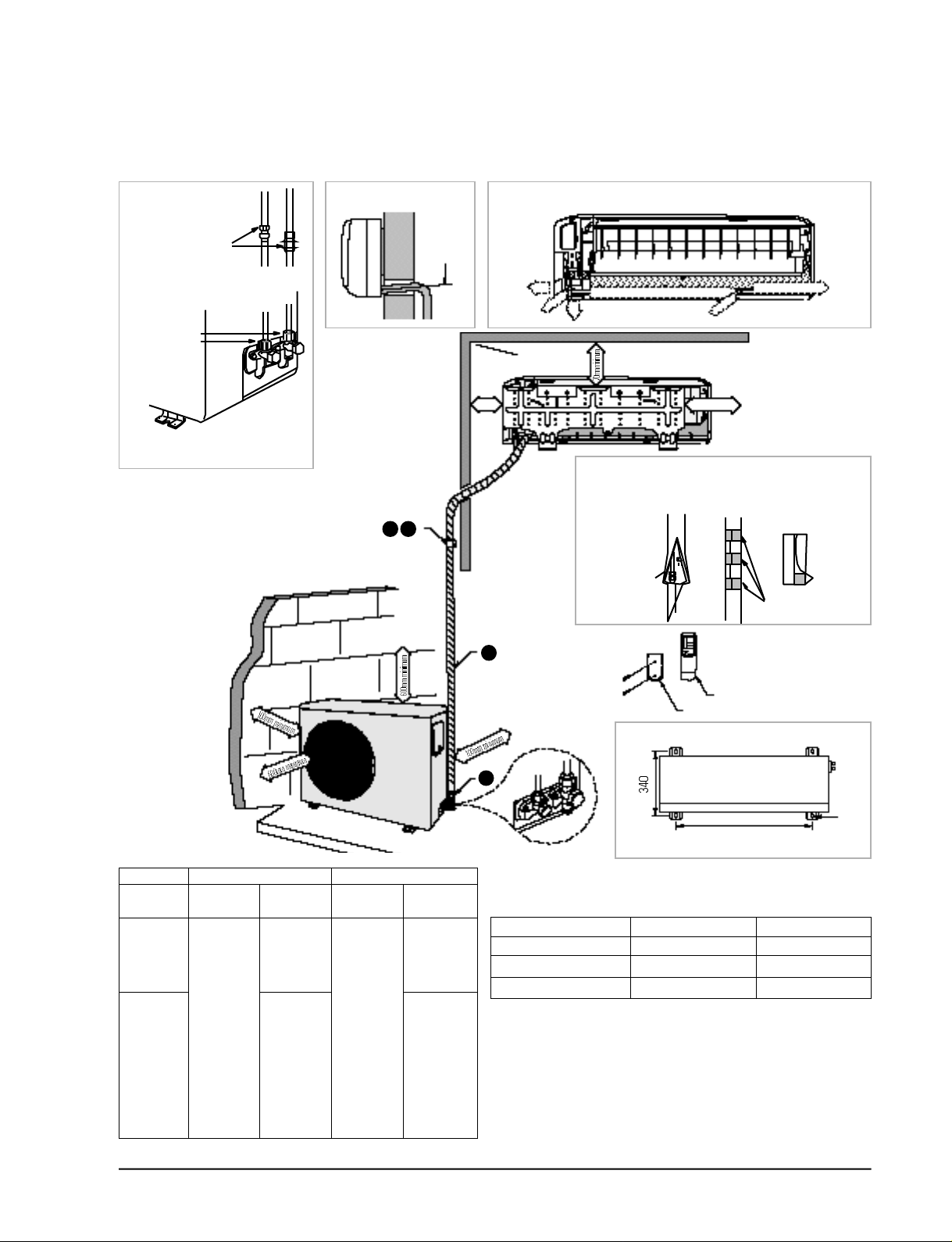
3-2-2 Installation diagram of indoor unit and outdoor unit
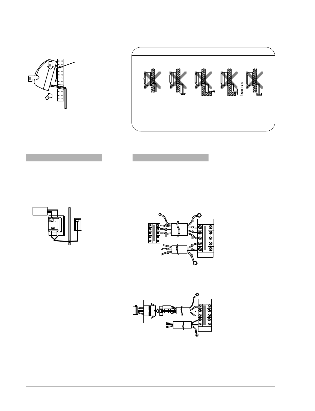
GAS LEAK TEST Slope of drain hose * Piping may be laid to the rear, left, right or down.
Avoid up
Indoor unit check
points
slopes
Right
Left
Outdoor unit
check points
* Check for gas leak from the flare nut
connections with leak detector.
5 6
250mm
m i n i m u m
4
Rear
Down
Insulation of pipe connection area
* Perform gas leakage test first, and insulate the pipe
connection area.
Use an insulation tube for insulation as shown in figure.
The insulation
tube shall be
properly finished
not to allow
any gap.
Left rear
350mm or more
Vinyl tape
(purchase locally)
Remote control
Remote control holder
Hole dimension of bolts for the outdoor unit
Insulation
tube
Coolant adjustment pro c e d u re
C l a s s
C o n n e c t i o n
pipe lengh
A i r- p u rg e
m e t h o d
C o o l a n t
a d j u s t m e n t
u n n e c e s s a ry
5m max
Refer to the
detailed
a i r- p u rg e
p ro c e d u re .
Add 10g of
c o o l a n t
5 ~ 1 0 m
<R-22> for
e v e ry 1m.
(Refer to
the detailed
c o o l a n t
c h a rg e
p ro c e d u re . )
Samsung Electronics
Air purg e
m e t h o d
P u rge air
using
a vacuum
pump or an
a d d i t i o n a l
c o o l a n t
c y l i n d e r.
R e f r i g e r a n t
q u a n t i t y
See table
r i g h t .
Add 10g of
c o o l a n t
<R-22> for
e v e ry 1m.
(Refer to
the detailed
c o o l a n t
c h a rg e
p ro c e d u re . )
10
Fix firmly if installed in an area affected by typhoons.
582
Coolant adjustment pro c e d u re
Outer diameter Fixing torque Final torque
ø6.35mm 160 200
ø12.7mm 500 550
ø15.8mm 700 750
Tighten the flare nut by hand first, and tighten firmly with a spanner
ø12
kg .cmAt installation At installation
3-5
Operating Instructions and Installation
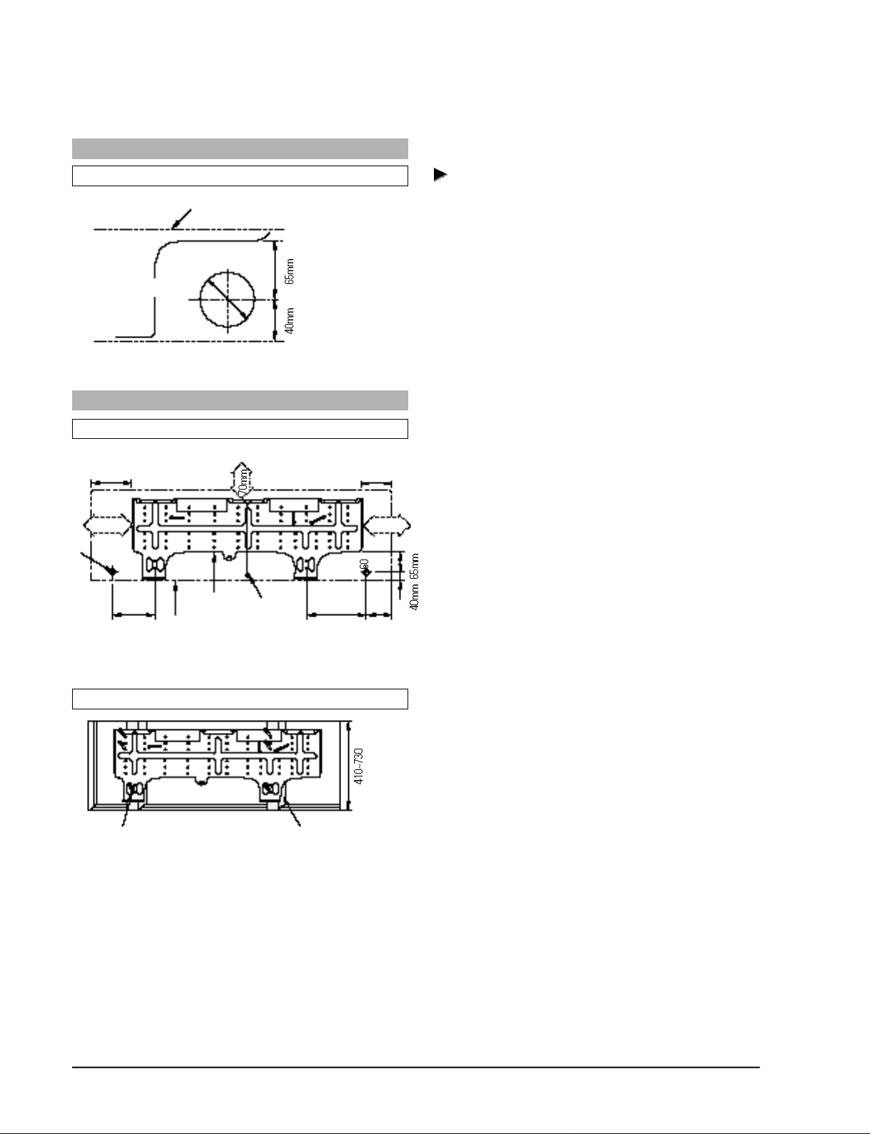
3-2-2(a) Fixing the Installation Plate
CUTTING A HOLE
When the refrigerant piping are hooked up from the rear.
Installation plate
Pipe hole (ø65mm)
MOUNTING THE INSTALLATION PLATE
When the installation plate is directly mounted on the wall.
250mm 145mm
Pipe hole
(ø65mm)
260mm
Installation plate
Indoor unit
Weight
200mm 100mm
Determine the pipe hole position for installation
and drill the pipe hole (65mm inner diameter)
so that it slants slightly downward.
1. Install the installation plate horizontally on
structural members (studs, etc.) in the wall.
2. To mount the installation plate on a concrete
wall with anchor bolts, utilize the anchor bolt
holes as illustrated in the left figure.
250mm350mm
3. When the anchor bolts are already driven in the
wall, also utilize the anchor bolts holes to secure
the installation plate. (If an anchor bolt is too
long, adjust the projecting length to 20mm or
less.)
Mounting at the window frame.
3-6
1. As the left Fig.
Fix the wood pillar at the wood frame and
install installation plate with screw tap.
2. Fix the wood pillar with enough strength to
bear the weight of the indoor unit.
Wood pillarScrew wood
Samsung Electronics
Operating Instructions and Installation
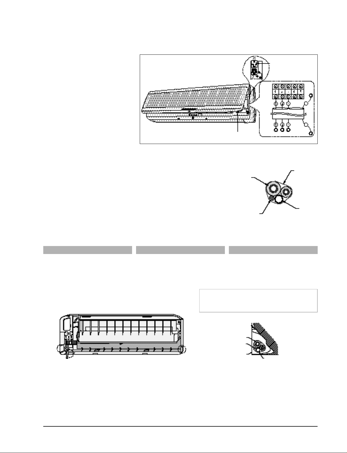
3-2-2(b) Wiring connection(Indoor unit)
1. Open the Grille and remove the
screw securing the cover.
AS-24**
2. AS-18**: Pass the assembly cable
through the rear of the indoor
unit and connect the assembly
cable to terminals 1~3.
*Each wire is labelled with the
corresponding terminal number.
AS-24**: Firmly connet the cable
connector with connector.(6pin,
4-cable)
3. Assembly every parts by contrary
order to disassembly.
3-2-2(c) Piping and drain hose installation
1 . Fix the drain hose right the refrigerant piping.
2. Be careful not to form a slack of the drain hose.
3. Do not allow the piping to jut out from the back of the indoor unit.
4. Insulate both of the refrigerant pipings so that dewing and troubles
may not happen.
5. Be careful in bending the pipes. The bending radius must be
100mm or larg e r.
Conneitor
AS-18**
Indoor
unit
Outdoor
unit
Screw
Tape
Piping
Drain hose
Assembly cable
A.Right-hand connection with piping C.Under-side connection with pipingB.Left-hand connection with piping
1. Cut out the knock-out piece from the
rightside of the rear body with a knife,
etc. Smooth the cut edges.
1. Cut out the knock-out piece from the
leftside of the rear body with a knife,
etc. Smooth the cut edges.
2. Cut out the Holder-pipe slit part.
3. Support the above section to be bent
with your hand and bend the pipes
there.
A
C
B
1. Cut out the knock-out piece from the
underside of the rear body with a knife,
etc. Smooth the cut edges.
2. Cut out the Holder-pipe on its slit part.
Set the drain hose in the inner part of the
indoor unit and the assembly cable in lower part of it.
Wind tape round them.
Piping
Assembly cable
Installation plate
Drain hose
Samsung Electronics
3-7
Operating Instructions and Installation
3-2-2(d) Indoor unit installation
DRAINAGE
1. Pass the pipes
Hook
here
t h rough the
hole in the
wall and hook
the indoor
unit to the
i n s t a l l a t i o n
plate at the
upper and
lower hooks.
2. Move the indoor unit to the right and
left to make sure that the unit is
s e c u rely hooked on to the installation
p l a t e .
1. Run the drain hose sloped downward .
2. Do not install the drain hose as illustrated below.
Do not form
a rise
3. Put water in the drain pan and make sure that the water is drained outdoor.
4. When connecting the extension drain hose, insulate the inside part of the
extension drain hose with shield.
3-2-2(e) Wiring connection(outdoor unit)
AUXILIARY POWER S/W WIRING CONNECTION
Do not put the
drain hose end
into water
Do not wave
the hose
Keep a distance
at least 5cm
or more
Ditch
Do not put the
drain hose end
in the ditch
A u x i l i a ry power S/W should be installed
near indoor unit so that each access is
p o s s i b l e .
Main/Outdoor unit power cords are
connected to upper/lower terminal of
a u x i l i a ry power S/W.
distributind
board
Auxiliary
power S/W
Indoor unit connector wire should be
connected to both indoor unit connector
( t e rminal board) and outdoor unit term i n a l
b o a rd as shown in the figure below.
AS-18**
(POWER CABLE)
<Indoor unit>
(ASSEMBLY CABLE)
AS-24**
(ASSEMBLY CABLE)
EARTH WIRE
<Outdoor unit>
EARTH WIRE
EARTH WIRE
3-8
(POWER CABLE)
<Indoor unit> <Outdoor unit>
EARTH WIRE
Samsung Electronics
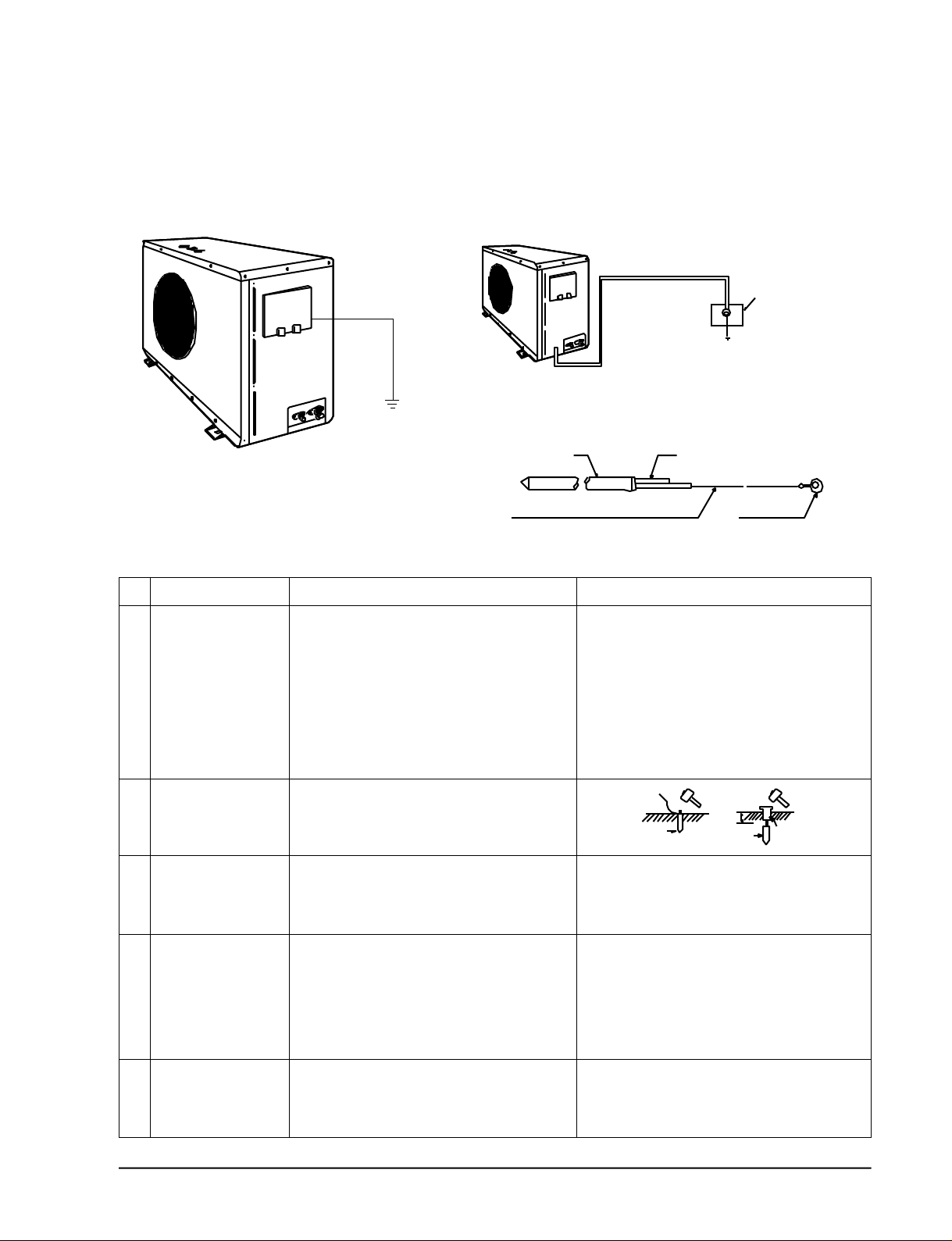
3-2-2(f) Grounding
(The Parts for this work are optional.)
Operating Instructions and Installation
• A g rounding terminal can be found on
the outdoor unit as illustrated.
1. When an existing grounding terminal is avilable.
( G rounding wire of ø1.6mm or larger<solid w i re > o r
2 m m2or larger <standard wire > )
Terminal used exclusively
for grounding.
Grounding resistance ;
Less than 100 ohms
(existing grounding electrode)
2. Use of a grounding electro d e .
• Specifications of grounding electro d e .
Steel coreCarbon plastic
PVC-Insulated(2mm2x3.5m), green Terminal, M4
No. JOB EXPLANATION PRECAUTIONS
1 Determine the • Suitable location • Avoid sandy or gravelly soil as its grounding
grounding position. a) Place that is always dank. resistance is high.
b) Hard soil rather than loose sandy soil. • The grounding wire for the telephone line cannot
be used for the grounding of the air conditioner.
• Unsuitable location • When the grounding electrode is to be installed
a) Where there are underground structures or under a place with heavy traffic, its wire must be
facilites such as gas pipes, water pipes, connected firmly with the utmost care.
telephone lines, underground cables, etc.
b) A place 2m or less from the lightning arrester
grounding electrode and its cable.
2 Drive the grounding a) Dig a hole to the size illustrated,
electrode into position. and drive in the grounding electrode.
b) Cover the top of the grounding
electrode with excavated soil.
3 Put the grounding a) If the grounding wire is too short, connect an • The grounding wire should be a green
wire in order. extention lead to it. Solder the joint and insulated wire of ø1.6mm or 2mm2or larger.
wrap it with tape. • The soldered joint should not be buried
b) Fasten the grounding wire with staples. underground.
4 Check the a) After grounding work, measure the grounding
workmanship, resistance with a grounding resistance tester.
and provide
corrective b) If the resistance is above a specified level,
measures if drive the grounding electrode in deeper
necessary. or increase the number of grounding
electrodes.
5 Connect the Secure the grounding wire to the
grounding grounding terminal of the air conditioner
wire to the air
conditioner.
Samsung Electronics
3-9
Operating Instructions and Installation
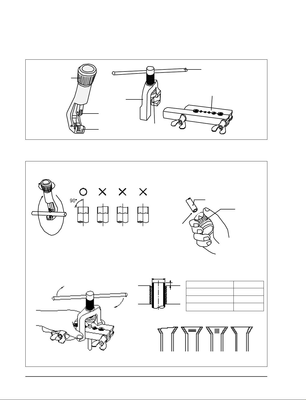
3-2-2(g) Flare modification
• Tools used
Tightening
knob
Cutting wheel
Clamp handle
Bar
Yoke
Roller
• Flare modification procedure
1) Cut the pipe using a pipe cutter.
Oblique Raughness Burr
3) Insert a flare nut into the pipe and modifty flare.
Cone
2) Remove burrs at the tip of the pipe cut.
Caution : Burrs not removed may result
in leakage of gas.
Pipe
Reamer
Point
down
3-10
D
A
• Unproper flaring
Inclined Surface
damaged
Outer diameter A(mm)
ø6.35mm 1.3
ø12.7mm 2.0
ø15.8mm 2.2
Cracked Uneven
thickness
Samsung Electronics
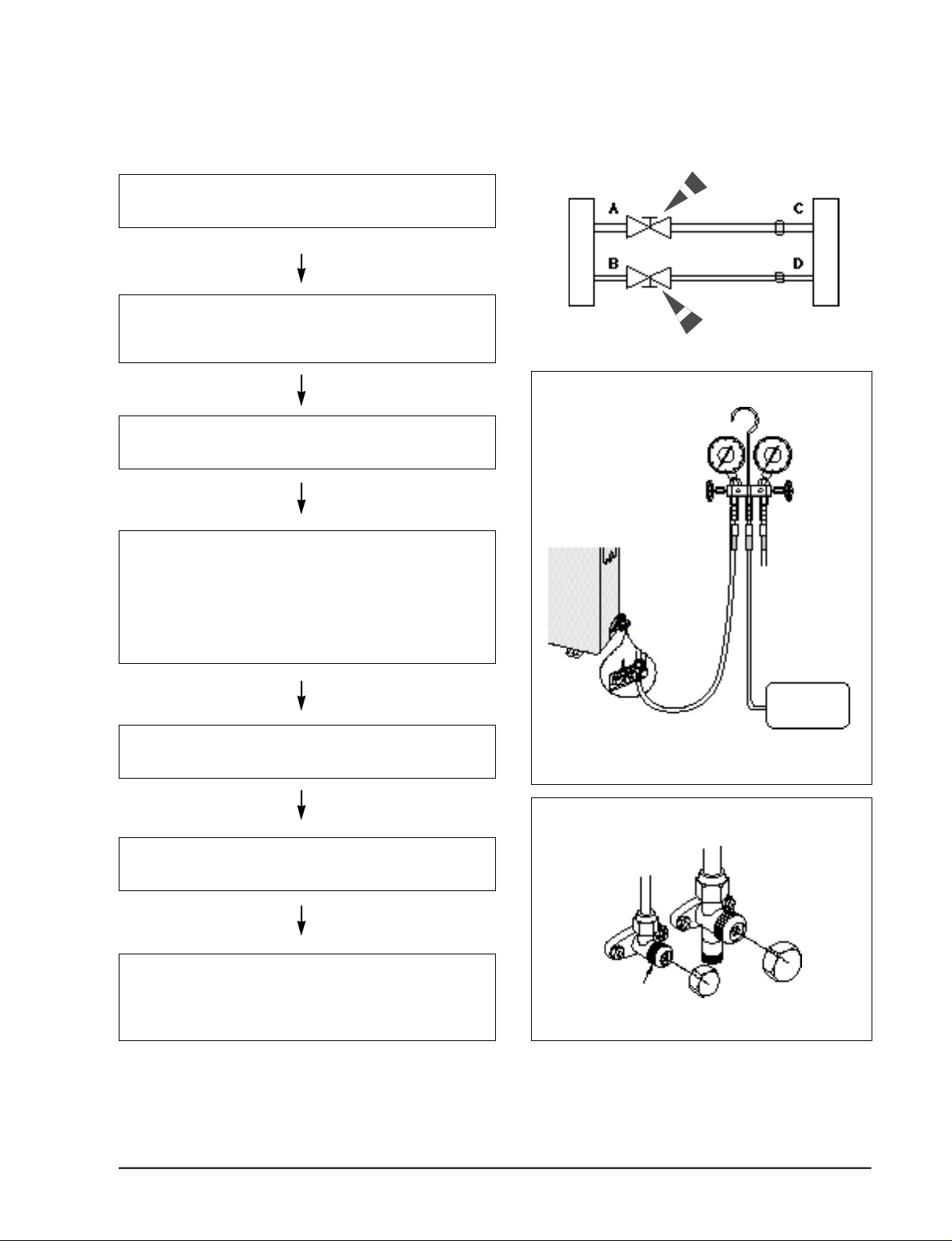
3-2-2(h) Air-Purge Procedure
Operating Instructions and Installation
1. Connect each assembly pipe to the appropriate valve on the
outdoor unit and tighten the flare nut.
2 Connect the charging hose of low pressure side of manifold
gauge to the packed valve having a service port (3/8” or
1/2” Packed valve) as shown at the figure.
3 Open the valve of the low pressure side of manifold gauge
counter-clockwise.
4. Purge the air from the system using vacuum pump for about
10 minutes.
- Close the valve of the low pressure side of manifold gauge
clockwise.
- Remove the hose of the low pressure side of manifold
gauge.
Outdoor unit
Indoor unit
Gas pipe side
Liquid pipe side
5. Set valve cork of both liquid side and gas side of packed
valve to the open position.
6. Mount the valve stem nuts to the 2-way and 3-way valve.
And mount the service port cap to 3-way valve.
7. Check for gas leakage.
- At this time, especially check for gas leakage from the
3-way valve’s stem nuts, and from the service port cap.
Valve stem
B
(liquid)
Vacuum Pump
A
(gas)
Stem cap
Samsung Electronics
3-11
 Loading...