

Page 1

5. Troubleshooting
5-1 Items to be checked first
1) The input voltage should be 198-264VAC.
The air conditioner may not operate properly if the voltage is out of this range.
2) The indoor unit and the outdoor unit shall be linked by 4 cables.
Check the terminals if the indoor unit and outdoor unit are properly linked by the same number of cables.
Otherwise the air conditioner may not operate pro p e r l y.
3) If a problem occurs as described in the table below, it is a symptom not related to the malfunction of the air
c o n d i t i o n e r.
NO
1
The operation indication LED (Green) blinks when a
power plug of the indoor unit is plugged in for the
first time.
2
• In a COOL operation mode, the compressor does not
operate at a room temperature than the setting
temperature that the compressor should operate.
3
Fan speed setting is not allowed in AUTO or DRY
mode.
4
Compressor stops operation intermittently in DRY
mode.
5
Timer LED only of the indoor unit lights up and the
air conditioner does not operate.
6
The compressor stops intermittently in a COOL
mode or DRY mode, and fan speed of the indoor unit
decreases.
Operation of air conditioner
Explanation
It indicates power is on. The LED stops blinking if the operation
ON/OFF button on the remote control unit is pushed.
• In happens after a delay of 3 minutes when the compressor is
reoperated. The same phenomenon occurs when a power is on.
• As a phenomenon that the compressor is reoperated after a
delay of 3 minutes, the indoor fan is adjusted automatically
with reference to a temperature of the air blew
• The speed of the indoor is changed automatically in DRY mode.
• Fan speed is 4 steps is selected automatically in AUTO mode.
Compressor operation is controlled automatically in DRY mode
depending on the room temperature.
Timer is being activated and the unit is in ready mode.
The unit operates normally if the timer operation is cancelled.
The compressor stops intermittently or the fan speed of the
indoor unit decreases to prevent inside/outside air frozen
depending on the inside/outside air temperature.
4 ) Indoor unit observes operation condition of the air conditioner, and displays self diagnosis details
on the display panel.
NO Display
1 OPERATING LED (GREEN) blinking (1Hz)
2 TIMER LED (YELLOW) blinking (5Hz)
3 OPERATING (GREEN), TIMER LED (YELLOW) blinking (5Hz)
4 FAN (GREEN) LED blinking (5Hz)
Samsung Electronics
Restore from power failure (input initial power)
Temperature sensor defective (open, short)
Indoor heat exchanger sensor defective (open, short)
Indoor fan malfunction (inoperative within 15 sec- less than
600rpm)
Self Diagnosis
5-1
Page 2
Troubleshooting
5-2 Fault Diagnosis by Symptom
5-2-1 No Power(completely dead)-Initial diagnosis
1 ) Checklist :
(1) Is input voltage normal? (198-264V~)
(2) Is AC power linked corre c t l y ?
(3) A re connections between primary side, secondary side of the power transformer
and PCB good.
(4) Is output voltage of DC regulator IC KA7812(IC01) normal? (11 . 5 V D C - 1 2 . 5 V D C )
(5) Is output voltage of DC regulator IC KA7805(IC02) normal? (4.5VDC-5.5VDC)
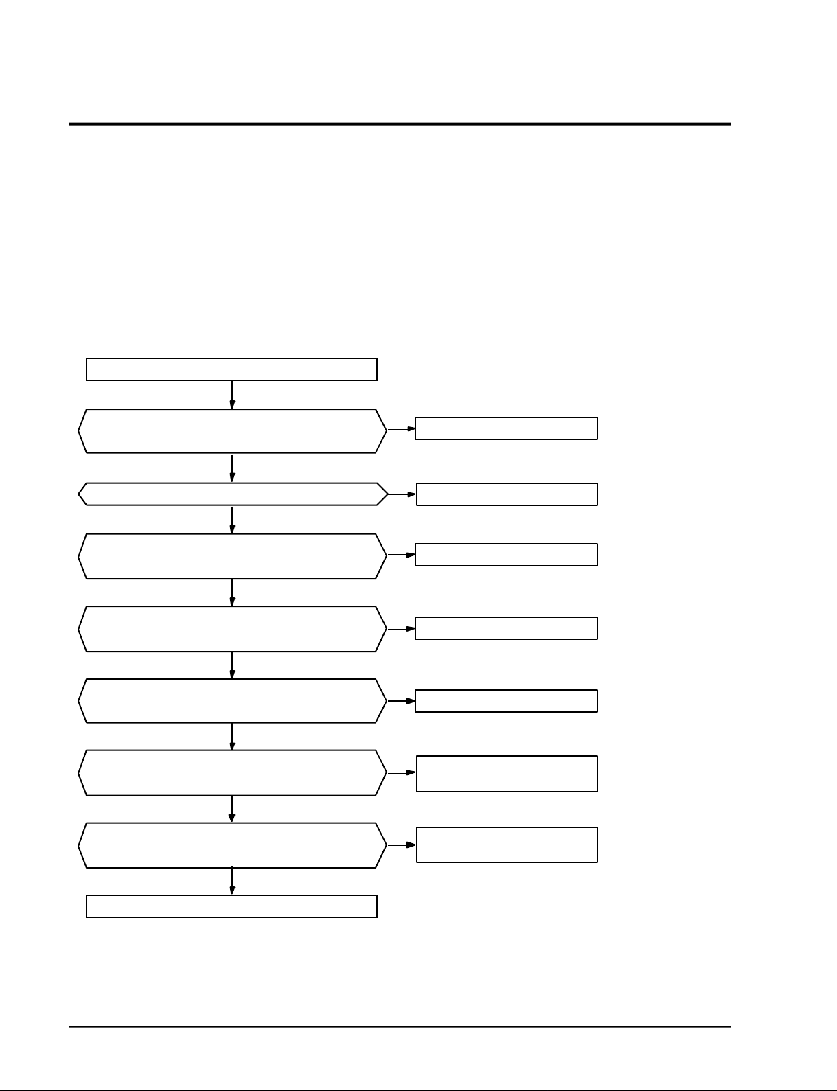
2 ) Troubleshooting pro c e d u re
Remove power cord and plug in again in approx. 5 seconds.
Is operating lamp lights on for
three minutes, and then goes off?
N
Check whether the fuse is normal? (F701)
Y
Check whether the output voltage of the trans
is normal? (AC 15V±3V)
Y
Check whether the DC 12V is normal?
(DC12±0.5V between "G" and "O" of the IC01)
Y
Check whether the DC 5V is normal?
(DC 5V±0.5V between "G" and "O" of the IC02)
Y
Is the harness properly connected(CN93, CN94)?
Y
Y
N
Replace the fuse (250V, 3.15A)
N
N
N
N
Harness check and replace
Normal
Replace the trans.
Replace the IC01.
Replace the IC02.
5-2
Check whether the display PCB is normal?
(Check the DC 5V, DC12V, wire, etc.)
Y
Replace the assembly main PCB.
N
Replace the assembly display PCB
Samsung Electronics
Page 3
5-2-2 When the Indoor Unit Fan Does Not Operate. (Initial Diagnosis)
1) Checklist :
(1) Is input voltage normal? (198-264V~)
(2) Is the indoor unit fan properly connected(CN73)?
(3) Is the starting codenser CR 71 properly soldere d ?
(4) Is HALL IC in indoor fan motor properly connected(CN43)?
(5) When in operation mode, does the indoor unit fan operate?
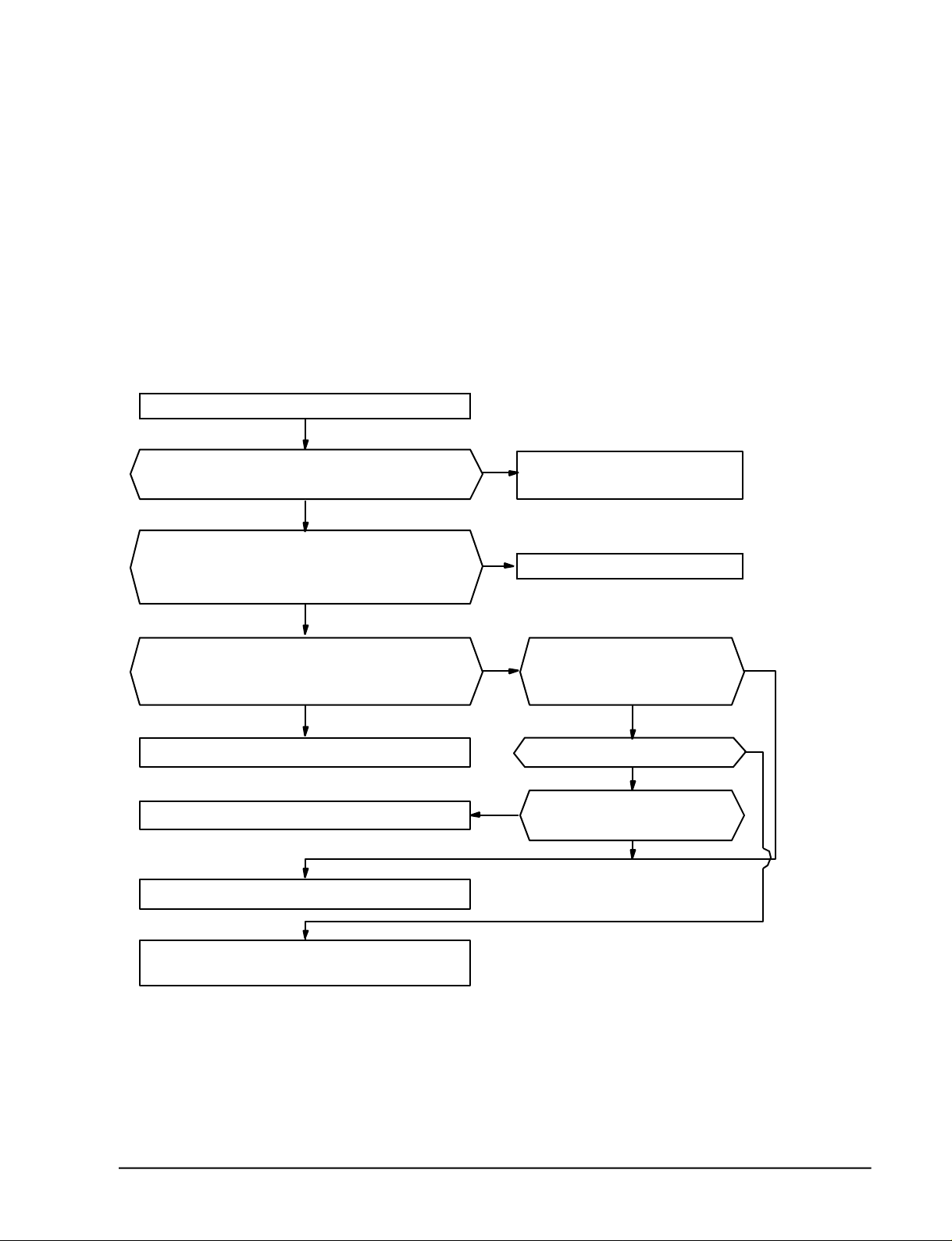
2 ) Troubleshooting pro c e d u re
Remove power cord and plug in again in approx. 5 seconds.
Y
Troubleshooting
Is operating lamp lights on for
three minutes, and then goes off?
Y
Check whether the indoor fan turns with the operation
lamp being turned on when the start/stop button of the
remote control is pressed?
N
•Is a voltage of above AC 240~300V applied to both ends
of theindoor fan connector (CN73)?
•Is pin #3 of the CN43 a square wave?
N
Replace the indoor fan motor or fan motor capacitor.
Replace the Q401 (KSC945Y).
Replace the micom (IC04).
N
Go to the item of "No power
parts" (Refer to page 5-2)
Y
Y
No problem (Normal)
Is pin #63 of the micom (IC04)
a square wave?
Y
Is pin #13 of the IC06 a square wave?
Y
Y
Is pin #24 of the micom (IC04)
a square wave?
N
N
N
Replace the SS71 (G3MB202PL).
Samsung Electronics
Replace the IC06.
5-3
Page 4

Troubleshooting
5-2-3 When the Outdoor Unit Does Not Operate. (Initial Diagnosis)
1 ) Checklist :
(1) Is input voltage normal? (198-264V~)
(2) Is the set temperature of the remote control higher than room temperature in COOL m o d e ?
(3) Is the CONNECTOR-WIRE OUTDOOR linked corre c t l y ?
(4) Is the indoor unit wire properly connected with the outdoor unit wire ?
2 ) Troubleshooting pro c e d u re
Remove power cord and plug in again in approx. 5 seconds.
Is operating lamp lights on for
three minutes, and then goes off?
Y
Check whether the compressor is activated in three minutes
after the operation lamp comes on when you press the
ON/OFF button of the remote control?
N
Is the wave of the micom (IC04) pin #62 high?
Y
Is the wave of the IC06 pin #14 low?
Y
Is the AC240V voltage between the skyblue wire and
Brown wire of the CN78?
Y
Is the outdoor unit magnetic contactor operate?
N
Go to the item of "No power
parts."
Y
N
N
N
N
No problem (Normal)
Replace the micom (IC04).
Replace the IC06.
Check the outdoor power.
Replace the magnetic contactor
5-4
Y
Replace the compressor.
Samsung Electronics
Page 5

5-2-4 When the UP/DOWN Louver Motor Does Not Operate. (Initial Diagnosis)
1) Checklist :
(1) Is input voltage normal? (198-264V~)
(2) Is the UP/DOWN louver motor properly connected with the connector (CN61)?
2 ) Troubleshooting pro c e d u re
Remove power cord and plug in again in approx. 5 seconds.
Troubleshooting
Is operating lamp blinking in 3 minutes and then lamp off?
Y
Does operation start when swing button of the remote
control unit pushed?
N
Voltage at pin #33-#36 of micom (IC04) change?
(Squarewave)
Y
Volatge at pin #10-#13 of IC05
KID65003AP change? (Squarewave)
Y
UP/DOWN louver motor is faulty.
N
Check as in the procedure
"No Power parts". Refer to page 5-2.
Y
N
N
Normal
Micom (IC04) is faulty.
Driver IC05 is faulty.
Samsung Electronics
5-5
Page 6

Troubleshooting
5-2-5 If Operation By Remote Control Unit Is Impossible. (Initial Diagnosis)
1) Checklist :
(1) Is operation selector switch of the indoor unit set at "REMOTE"?
2) Troubleshooting pro c e d u re
Remove power cord and plug in again approx. 5 Seconds.
N
Is operating lamp blinking in 3 minutes and then lamp off?
Y
Check as in the procedure "No Power
parts". Refer to page 5-2.
"Beep" sound heard from the indoor unit when ON/OFF
button on the remote control unit pushed?
N
Voltage of battery less than 2.5V?(Remote Control Unit)
N
LCD display status of REMOCON normal?
Y
Transmission display lamp ( ) blinking when
ON/OFF button on the remote control unit pushed?
Y
Voltage at collecter of Q601 or Q602 change?
(Remote Control Unit)
Y
Voltage at pin #26 of micom (IC04) change?
Y
Micom (IC04) is faulty.
Y
Y
N
N
N
Q601 (KSH29, C4375) or
Normal
Replace battery.
LCD is faulty.
Replace button.
Q602 (2SC1623) is faulty.
LE61, LE62 (CL-1L5E) is faulty.
N
Receiver module
(GP1U271R) is faulty.
5-6
Samsung Electronics
Page 7

5-3 PCB Inspection
5-3-1 Cautions for Part Replacement
Troubleshooting
1 . The human body carries much static
e l e c t r i c i t y. Before touching a part for re p a i r,
replacement or the similar purpose, be sure
to touch a grounded metallic portion by
hand to let the static electricity go thro u g h
the matallic portion to the earth.
Espectially when handling any micro
computer or IC, carefully remove such static
electricity before touching them.
2 . When repairing any part on a work bench,
be sure to place an insulative sheet on the
bench and always keep the sheet surface
neat without any metal fragments. If any
such fragment touches a part, a secondary
t rouble will possibly be caused in the part.
3. B e f o re replacing any parts, be sure to turn
o ff the power supply. If such replacement is
done with the power supply kept on, an
electric shock, short circuit or destruction of
a part may re s u l t .
4. During replacement or repair of a part,
c a refully handle it : The printed circ u i t
b o a rd has fine lead wires (jumper wire s )
and glass-made parts (diode) on its
substrate.
So if a circuit board is roughly handled,
such lead wires and parts will be easily
b roken or damaged by bending or shock.
5 . When soldering the lead wires of any new
part, be sure to polish them using an emery
paper or the like before solding them.
Since the lead wires of any new part are
c o v e red with an oxide film, solder cannot
a d h e re to the lead wires if not polished.
6 . When soldering any part, care should be
e x e rcised not to apply any high-wattage
soldering iron to the part for a long time.
Some parts are of so low a heat re s i s t a n c e
that they may be broken or have the
p roperties changed if a soldering iron is so
applied (Otherwise, the pattern may
possibly be separated and raised).
7. The heat of the soldering iron should be
t r a n s f e red to the entire object to be
s o l d e red. If the solder pieces are not well
fused due to insufficient transfer of the heat
f rom the soldering iron, no satisfactory
electrical continuity can be assured even if
the soldered objects appear well connected
to each other.
8 . The solder used should be limited to a
minimum. If excessive solder is used, it will
cause inter-pattern contact, which may
cause malfunction of the circ u i t .
5-3-2 Procedure
The parts should be replaced in the following pro c e d u re .
Check for any faulty part.
Detach the faulty part.
Replace it with a new part.
Check the operation of the new part.
The repair is completed.
Samsung Electronics
5-7
Page 8

Troubleshooting
5-3-3 Detailed Procedure
No.
Pull out the power plug from
1
the AC terminal and check
the fuse on the PCB assembly
Turn the power on.
2
If lamp blinks trouble is not
related to the items 1 through
4 on the right.
Set operating mode when
3
RMC switch pushed.
1. COOL mode
2. Fan speed [AUTO]
3. Set temperature lower
4. Continuous operation.
Malfunction
than room temperature
Checking point (symptoms)
1. Is the fuse blown?
Voltage check
1. AC voltage at both end of transformer Primary?
198 - 264V~
2. AC voltage at both end of transformer
secondary?
15 - 25V~
3. DC voltage at OUT and GND of IC01
(KA7812)? 12VDC
4. DC voltage at OUT and GND of IC02? 5VDC
5. DC voltage at Q201 Base and GND change?
squarewave
1. Compressor does not operate.
Causes
1. Voltage over
2. Indoor unit fan motor short-circuit.
1. Irregular power code or power fuse,
or poor wiring.
2. Transformer is faulty.
3. Power circuit is faulty.
4. Power circuit is faulty.
5. Q201 is faulty.
D101~D105 (D4G*4) is faulty.
1. Temperature of Heat exchange
is lower.
2. PCB is faulty.
Set operating mode when
4
RMC switch pushed.
1. [FAN] mode
2. Fan speed [HI]
3. Continuous operation
5-8
1. Voltage at 3 5 both ends of CN73 :
above 190V~
2. Indoor unit fan motor does not operate.
1. Indoor unit fan motor is faulty.
2. Poor connection of indoor fan motor
and connector of RPM sensing (CN43)
Samsung Electronics
Page 9

5-4 Fault Diagnosis of Major Parts
Troubleshooting
Parts
Temp.Sensor
Heat ex. Sensor
Indoor Fan Motor
Diagnosis
Measure resistance with a tester.
Normal 8KΩ~27KΩ at ambient temperature (+0°C ~ +30°C)
Abnormal ∞, O Ω … open or short
Measure resistance between terminals (CN72) with a tester
Normal At ambient temperature (10°C ~ 30°C)
Between Resistance
Yellow, Blu 190±10Ω
Yellow, Red 240±15Ω
Abnormal
Measure the voltage between ground and signal wire of the fan motor
Normal
Between Voltage
Gray, Orange 05V~4.5V
Outdoor Fan Motor
Stepping Motor
(UP/DOWN swing motor)
Yellow, Orange 5V
Abnormal Abnormal if voltage does not change from 0V to 5V.
Normal At ambient temperature (10°C ~ 30°C)
between Resistance
Black, Yellow 189±10Ω
Black, Red 220±10Ω
Abnormal ∞, O Ω … open or short
Measure resistance between red wire and each terminal.
Normal Approx. 380Ω at ambient temperature (20°C ~30°C)
Abnormal ∞, O Ω … open or short
Samsung Electronics
5-9
 Loading...