

ROOM AIR CONDITIONER
INDOOR UNIT
AS070VE/DOK
AS071VE/DOK
AS074VE/DOK
AS075VE/DOK
AS090VE/DOK
AS091VE/DOK
AS094VE/DOK
AS095VE/DOK
AS120VE/DOK
AS121VE/DOK
AS124VE/DOK
AS125VE/DOK
SERVICE
OUTDOOR UNIT
AX070VE/DOK
AX071VE/DOK
AX074VE/DOK
AX075VE/DOK
AX090VE/DOK
AX091VE/DOK
AX094VE/DOK
AX095VE/DOK
AX120VE/DOK
AX121VE/DOK
AX124VE/DOK
AX125VE/DOK
Manual
CONTENTSAIR CONDITIONER
1. Pre c a u t i o n s
2. Product Specifications
3. Operating Instructions and
I n s t a l l a t i o n
4. Disassembly and Reassembly
5. Tro u b l e s h o o t i n g
6. Exploded Views and Parts List
7. Block Diagrams
8. PCB Diagrams
9. Wiring Diagrams
10. Schematic Diagrams

© Samsung Electronics Co., Ltd. JAN. 1998.
Printed in Korea.
Code No. DB81-10123A(1)
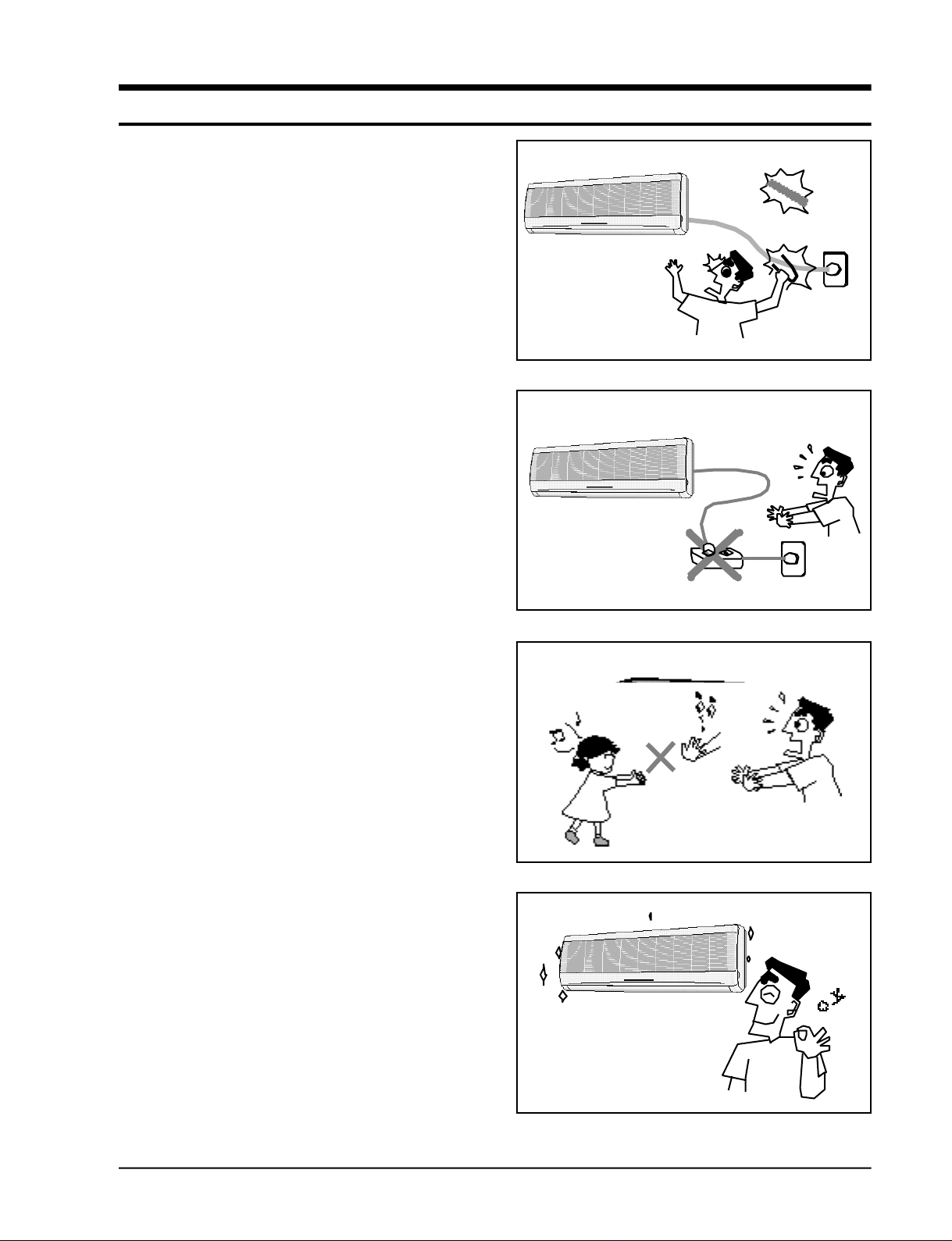
1. Precautions
1 . Warning: Prior to re p a i r, disconnect the
power cord from the circuit bre a k e r.
2 . Use proper parts: Use only exact re p l a c e-
ment parts. (Also, we recommend re p l a c i n g
parts rather than repairing them.)
3 . Use the proper tools: Use the proper tools
and test equipment, and know how to use
them. Using defective tools or test equipment may cause problems later- i n t e r m i t t e n t
contact, for example.
4 . Power Cord: Prior to re p a i r, check the
power cord and replace it if necessary.
5 . Avoid using an extension cord, and avoid
tapping into a power cord. This practice
may result in malfunction or fire .
6 . After completing repairs and re a s s e m b l y,
check the insulation resistance. Pro c e d u re :
Prior to applying power, measure the re s i stance between the power cord and the
g round terminal. The resistance must be
g reater than 30 megohms.
Fig. 1-1 Avoid Dangerous Contact
Fig. 1-2 No Tapping and No Extension Cords
7 . Make sure that the grounds are adequate.
8 . Make sure that the installation conditions
a re satisfactory. Relocate the unit if necess a r y.
9 . Keep children away from the unit while it is
being re p a i re d .
1 0 . Be sure to clean the unit and its surro u n d-
ing are a .
Fig. 1-3 No Kids Nearby!
Fig. 1-4 Clean the Unit
Samsung Electronics
1-1

M E M O
1-2
Samsung Electronics
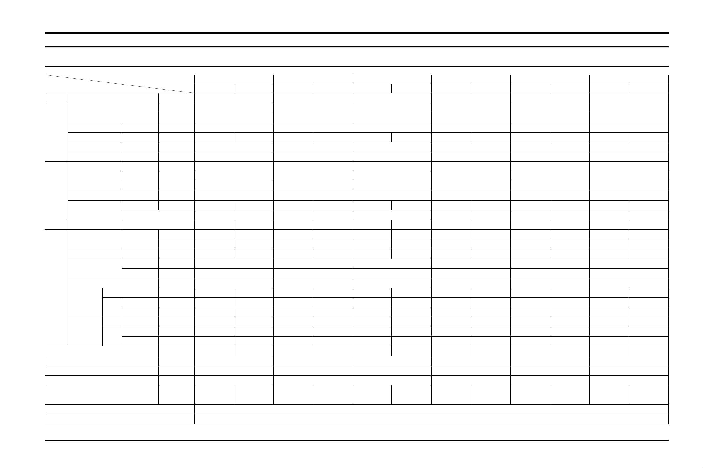
2. Product Specifications
2-1 Table
Model
Item
Type -
Cooling BTU/h
Dehumiditying I/h
Performance
Power
Size
Heat exchanger
Refrigerant control unit
Freezer oil capacity
Refrigerant to change(R-22)
Protection device
Cooling test Condition
Maximum operation Condition
Air volume Cooling m3/min
Noise Cooling dB
Energy efficiency ratio Cooling BTU/h.W
Power V-Hz
Power Consumption Cooling W
Operating Current Cooling A
Power factor Cooling %
Starting current A
Power cord Length m
Number of core wire
Fuse capacity A
Outer Width x Height mm
dimension x Depth inch
Weight kg
Refrigerant pipe Liquid OD(mm)x L(m)
GAS
Drain hose ID(mm)x L(m)
Compressor Type
Motor Type
Rated output W
Blower Type
Motor Type
Rated output W
A S 0 7 0 V E / A S 0 7 1 V E / A S 0 7 4 V E / A S 0 7 5 V E
Indoor unit Outdoor unit
Wall-mounting
7500
1.2
6.0
35 45
11.2
1-220 / 240-50
670
2.8
99.7
17.0
2 -
250V 10/16A
3.15 -
815x298x182 720x525x245
32.08x11.73x7.17 28.35x20.67x9.65
9.6 27
ø6.35 x 5
ø9.52 x 5
ø17 x 2000
- Rotary
- -
- 675
Cross-fan Propeller
Resin Die casting
35 15
2Row 12Step 1Row 20Step
CAPILLARY TUBE
280
670
- MST24AMN
-12008
A S 0 7 0 V D / A S 0 7 1 V D / A S 0 7 4 V D / A S 0 7 5 V D
Indoor unit Outdoor unit
Wall-mounting
7500
1.2
6.0
35 45
11.2
1-200 / 220-50
670
3.2
95.2
17.0
2 -
250V 10/16A
3.15 -
815x298x182 720x525x245
32.08x11.73x7.17 28.35x20.67x9.65
9.6 27
ø6.35 x 5
ø9.52 x 5
ø17 x 2000
- Rotary
- -
- 685
Cross-fan Propeller
Resin Die casting
35 15
2Row 12Step 1Row 20Step
CAPILLARY TUBE
280
690
- MST24AMM
-12008
INDOOR UNIT : DB27°C WB19°C OUTDOOR UNIT : DB35°C WB24°C
INDOOR UNIT : DB32°C WB23°C OUTDOOR UNIT : DB43°C WB26°C
A S 0 9 0 V E / A S 0 9 1 V E / A S 0 9 4 V E / A S 0 9 5 V E
Indoor unit Outdoor unit
Wall-mounting
9000
1.6
6.1
35 45
10.2
1-220 / 240-50
880
4.0
91.7
22.0
2 -
250V 10/16A
3.15 -
815x298x182 720x525x245
32.08x11.73x7.17 28.35x20.67x9.65
9.6 28
ø6.35 x 5
ø9.52 x 5
ø17 x 2000
- Rotary
- -
- 895
Cross-fan Propeller
Resin Steel
35 15
2Row 12Step 1Row 20Step
CAPILLARY TUBE
360
800
- MRA12037
-12007
A S 0 9 0 V D / A S 0 9 1 V D / A S 0 9 4 V D / A S 0 9 5 V D
Indoor unit Outdoor unit
Wall-mounting
9000
1.6
6.1
35 45
10.2
1-220 / 220-50
880
4.2
95.2
22.0
2 -
250V 10/16A
3.15 -
815x298x182 720x525x245
32.08x11.73x7.17 28.35x20.67x9.65
9.6 28
ø6.35 x 5
ø9.52 x 5
ø17 x 2000
- Rotary
- -
- 890
Cross-fan Propeller
Resin Steel
35 15
2Row 12Step 1Row 20Step
CAPILLARY TUBE
360
740
- MRA12056
-12007
A S 1 2 0 V E / A S 1 2 1 V E / A S 1 2 4 V E / A S 1 2 5 V E
Indoor unit Outdoor unit
Wall-mounting
12000
1.9
7.8
38 49
10.2
1-220 / 240-50
1180
5.0
98.3
30.0
2 -
250V 10/16A
3.15 -
815x298x182 720x525x245
32.08x11.73x7.17 28.35x20.67x9.65
9.6 31
ø6.35 x 5
ø12.7 x 5
ø17 x 2000
- Rotary
- -
- 1210
Cross-fan Propeller
Resin Die casting
35 20
2Row 12Step 1Row 20Step
CAPILLARY TUBE
410
930
- MRA12030
-12008
A S 1 2 0 V D / A S 1 2 1 V D / A S 1 2 4 V D / A S 1 2 5 V D
Indoor unit Outdoor unit
Wall-mounting
12000
1.9
7.8
38 49
10.2
1-200 / 220-50
1180
5.9
90.9
36.0
2 -
250V 10/16A
3.15 -
815x298x182 720x525x245
32.08x11.73x7.17 28.35x20.67x9.65
9.6 31
ø6.35 x 5
ø12.7 x 5
ø17 x 2000
- Rotary
- -
- 1215
Cross-fan Propeller
Resin Steel
35 20
2Row 12Step 1Row 20Step
CAPILLARY TUBE
410
780
- MRA98706
-12008
Samsung Electronics
2-1
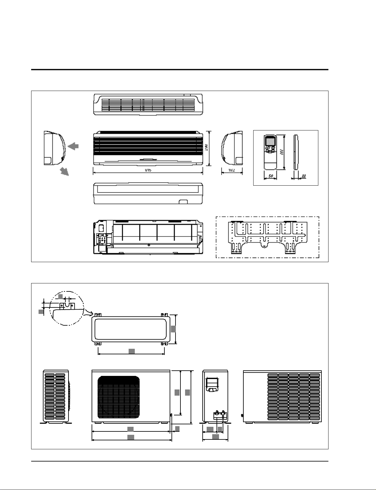
2-2 Dimensions
2-2-1 Indoor Unit
Air out
(Front view) (Remote control)
Air
in
2-2-1 Outdoor Unit
(Rear view)
(Front view)
Installation plate
(Rear view)
2-2
Samsung Electronics
2-3 Low pressure & Current Data
Indoor Unit : A S 0 7 0 V E / A S 0 7 1 V E
A S 0 7 4 V E / A S 0 7 5 V E
11
10
9
8
7
6
5
4
3
25
30 4035 45 50
Outdoor Inlet air D. B. temp.(°C)
Outdoor Unit : A X 0 7 0 V E / A X 0 7 1 V E
A X 0 7 4 V E / A X 0 7 5 V E
14
13
12
11
10
9
8
7
6
5
4
3
25
30 4035 45 50
Outdoor Inlet air D. B. temp.(°C)
Samsung Electronics
2-3
Product Specifications
Indoor Unit : A S 0 7 0 V D / A S 0 7 1 V D
A S 0 7 4 V D / A S 0 7 5 V D
11
10
9
8
7
6
5
4
3
25
30 4035 45 50
Outdoor Inlet air D. B. temp.(°C)
Outdoor : Unit A X 0 7 0 V D / A X 0 7 1 V D
A X 0 7 4 V D / A X 0 7 5 V D
14
13
12
11
10
9
8
7
6
5
4
3
25
30 4035 45 50
Outdoor Inlet air D. B. temp.(°C)
2-4
Samsung Electronics
Product Specifications
Indoor Unit : A S 0 9 0 V E / A S 0 9 1 V E
A S 0 9 4 V E / A S 0 9 5 V E
11
10
9
8
7
6
5
4
3
25
30 4035 45 50
Outdoor Inlet air D. B. temp.(°C)
Outdoor : Unit A X 0 9 0 V D / A X 0 9 1 V E
A X 0 9 4 V D / A X 0 9 5 V E
14
13
12
11
10
9
8
7
6
5
4
3
25
30 4035 45 50
Outdoor Inlet air D. B. temp.(°C)
Samsung Electronics
2-5

Product Specifications
Indoor Unit : A S 0 9 0 V D / A S 0 9 1 V D
A S 0 9 4 V D / A S 0 9 5 V D
11
10
9
8
7
6
5
4
3
25
30 4035 45 50
Outdoor Inlet air D. B. temp.(°C)
Outdoor Unit : A X 0 9 0 V D / A X 0 9 1 V D
A X 0 9 4 V D / A X 0 9 5 V D
14
13
12
11
10
9
8
7
6
5
4
3
25
30 4035 45 50
Outdoor Inlet air D. B. temp.(°C)
2-6
Samsung Electronics
Product Specifications
Indoor Unit : A S 1 2 0 V E / A S 1 2 1 V E
A S 1 2 4 V E / A S 1 2 5 V E
11
10
9
8
7
6
5
4
3
25
30 4035 45 50
Outdoor Inlet air D. B. temp.(°C)
Outdoor Unit : A X 1 2 0 V E / A X 1 2 1 V E
A X 1 2 4 V E / A X 1 2 5 V E
14
13
12
11
10
9
8
7
6
5
4
3
25
30 4035 45 50
Outdoor Inlet air D. B. temp.(°C)
Samsung Electronics
2-7

Product Specifications
Indoor Unit : A S 1 2 0 V D / A S 1 2 1 V D
A S 1 2 4 V D / A S 1 2 5 V D
11
10
9
8
7
6
5
4
3
25
30 4035 45 50
Outdoor Inlet air D. B. temp.(°C)
Outdoor Unit : A X 1 2 0 V D / A X 1 2 1 V D
A X 1 2 4 V D / A X 1 2 5 V D
14
13
12
11
10
9
8
7
6
5
4
3
25
30 4035 45 50
Outdoor Inlet air D. B. temp.(°C)
2-8
Samsung Electronics
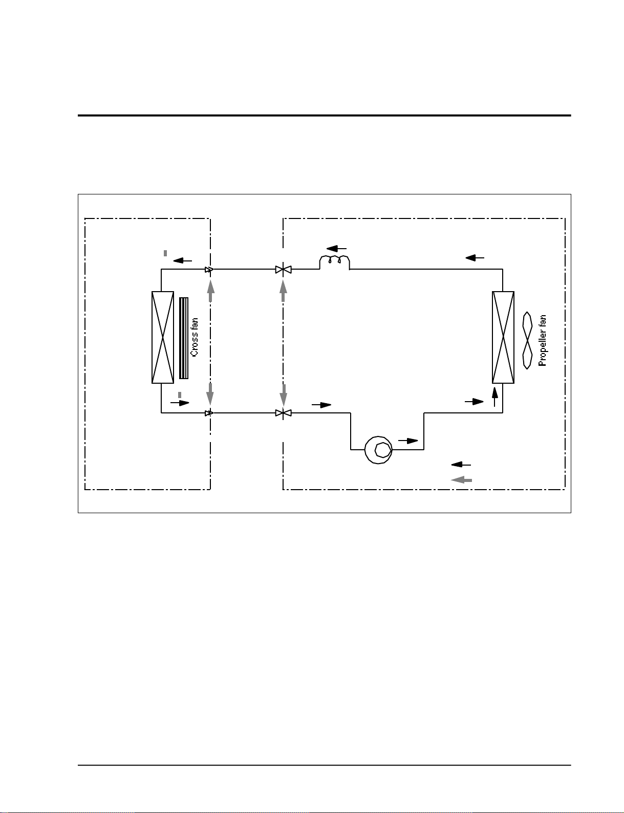
2-4 Refrigerating Cycle Block Diagram
INDOOR UNIT
Heat
exchanger
(Evaporator)
OUTDOOR UNIT
Capillary tube
T
Liquid side
T
Gas side
2-way valve
3-way valve
Compressor
Heat
exchanger
(Condenser)
Cooling
Gas leak check point
Samsung Electronics
2-9

M E M O
2-10
Samsung Electronics
3. Operating Instructions and Installation
3-1 Operating Instructions
3-1-1 Name & Function of Key in remote controller
NO
NAMED OF KEY
1
2
3
MODE
4
5
6
7
8
TURBO
OFF
(UP)
(DOWN)
On/Off Button. Use this button to start and stop air conditioner.
Temp. up button. If the button is pressed once,
the setting temperature is increased by 1°C
Temp. up button. If the button is pressed once,
the setting temperature is decreased by 1°C
Each time you press this button,
MODE is changed in the following order.
Use this button to provide heavy duty cooling & Heating for 30 minutes.
Set up the reserve or cancel the timer on and timer off quickly
Use this button for sleep operation.
(The SLEEP mode can be selected at COOL and HEAT mode.)
Adjusts air flow vertically.
Each time you press this button,
BLADE-H rotates by 10.58° (Changable range 42.3°)
Each time you press this button,
FAN SPEED is changed in the following order.
FUNCTION OF KEY
9
C
O
10
V
E
R
11
12
13
14
15
Samsung Electronics
T
I
M
E
R
ON TIMER
OFF TIMER
SET
CANCEL
TIME
(UP)
(DOWN)
Set up the time that operation start.
Set up the time that operation stop.
Use this button to reserve the timer on.
Use this button to reserve or cancel the timer on and timer off.
If the button is pressed once, the time increase by one minute
during the time set mode, and ten minutes during the timer set mode.
If the button is pressed once, the time decrease by one minute
during the time set mode, and ten minutes during the timer set mode.
Without regard to ON/OFF condition in remote controller,
use this button to set current time.
Adjust the current time using button.
(Data can be transmitted after setting up the time)
3-1
3-1-1 Name & Function of Key in remote controller
Operating Instructions and Installation
1. A U TO MODE : In this mode, operation
C O O L mode is selected automatically by the
room temperature of initial operation.
Operation Type
Tr≥ 24.5°C+∆T Compressor ON
Cool Operation
Tr≤ 24°C+∆T Compressor OFF
∆T= -1°, -2°C, 0°C+1°C+2°C
∆T is controlled by setting temperature
up/down key of remote contro l l e r
* FAN SPEED : A U TO
2. C O O L MODE : The unit operates accord i n g
to the diff e rence between the setting and
room temperature. (18°C~30°C)
3. D RY MODE : Has 3 states, each determined
by room temperature .
The unit operates in DRY m o d e .
*Co m p ressor ON/OFF Time is contro l l e d
compulsorily(can not set up the fan speed,
always bre e z e ) .
* P rotective function : Low temperature
release. (Prevention against fre e z e )
Room Temp
4. TURBO MODE : This mode is available in
A U TO, COOL, DRY, FAN MODE.
When this button is pressed at first, the air
conditioner is operated “powerful” state for
30 minutes re g a rdless of the set temperat u re, room temperature .
When this button is pressed again, or when
the operating time is 30 minutes, turbo
operation mode is canceled and returned to
the previous mode.
*But, if you press the TURBO button in DRY
or FAN mode that is changed with A U TO
mode automatically.
5 . S L E E P MODE : Sleep mode is available
only in COOL m o d e .
The operation will stop after 6 hours.
*In COOL mode : The setting temperature
is automatically raised by 1°C each 1hour
When the temperature has been raised by
total of 2°C, that temperature is maint a i n e d .
6. FAN SPEED : Manual (3 step), Auto (4 step)
Fan speed automatically varies depending
on both the diff e rence between setting and
the room temperature .
3-2
Samsung Electronics
Operating Instructions and Installation
8 . C O M P U L S O RY O P E R ATION :
For operating the air conditioner without
the remote contro l l e r.
* A U TO : The operating is the same function that A U TO MODE in the remote cont ro l l e r.
9 . SWING : BLADE-H is rotated vertically by
the stepping motor.
*Memory louver : When ON/OFF button is
p ressed at stop state, the BLADE-H re t u r n s
to its original location which is operating
state before stop
*Swing auto : The BLADE-H can ro t a t e
within about 10,500 in the original position
set by the SWING SET button.
*Swing Set : Press the button under the
remote control is displayed on LCD the ,
and the blades move up and down, about 43°.
If the one more time press the button, blatles location is stop.
1 0 . Quick OFF TIMER: OFF timer (quick timer)
allows reservation or cancel the timer on
and timer off quickly
When OFF timer button is pressed at operating state, LCD displays the polling state
s e q u e n t i a l l y.
The LCD also displays the time re m a i n i n g .
11 . 24-Hour ON/OFF Real Setting Ti m e r. : The
air conditioner is turned ON at a specified
time using .
ON TIMER
OFF TIMER : The air Conditioner is turned
OFF at a specified time using .
OFF TIMER
*ON TIMER : Only timer LED lights on.
*OFF TIMER : Both timer and operation
LED lights on.
*3 minutes delay timer.
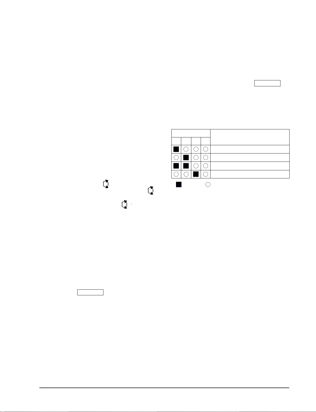
1 4 . SELF Diagnosis
LED DISPLAY
o p e r-
T I M E R
a t i o n
FA N
Tu r b o
Check Point
I n t e r ruption of electric power and Power on.
Abnormal condition of the room sensor.
Abnormal condition of the indoor unit's heat exchanger sensor.
Indoor unit fan motor lock.
L E D
:
b l i n k i n g
: LED off
1 5 . TIME SHORTENING : If the "Time short"
connector pin is shorted on the main P. C. B,
the compressor's three minutes delay function is cancelled, and each operation time is
shortened to one fiftieth of its original time.
1 6 . BUZZER SOUND : Whenever the ON/OFF
button is pressed or whenever change
occurs to the condition which is set up or
select, the compulsory operation mode,
buzzer is sounded "beep"
Samsung Electronics
3-3

3-2 Installation
3-2-1 Selecting Area for Installation
Select an area for installation that is suitable
to the customer's needs.
3-2-1(a) Indoor Unit
1 . Make sure that you install the indoor unit in
an area providing good ventilation. It must
not be blocked by an obstacle affecting the
airflow near the air inlet and the air outlet.
2 . Make sure that you install the indoor unit in
an area allowing good air handling and
endurance of vibration of the indoor unit.
3. Make sure that you install the indoor unit in
an area where there is no source of heat or
vapor nearby.
4 . Make sure that you install the indoor unit in
an area from which hot or cool air is spre a d
evenly in a ro o m .
5 . Make sure that you install the indoor unit in
an area away from TVs, audio units, cordless phones, fluorescent lighting fixture s
and other electrical appliances (at least 1
m e t e r ) .
6 . Make sure that you install the indoor unit in
an area which provides easy pipe connection with the outdoor unit, and easy
drainage for condensed water.
(Fix the unit firmly if it is mounted in a
high place.)
3 . Make sure that you install the outdoor unit
in area providing good ventilation and
which is not dusty. It must not be blocked
by any obstacle affecting the airflow near
the air inlet and the air outlet.
4 . Make sure that you install the outdoor unit
in area free from animals or plants.
5 . Make sure that you install the outdoor unit
in area not blocking the traff i c .
6. Make sure that you install the outdoor unit
in area easy to drain condensed water fro m
the indoor unit.
7. Make sure that you install the outdoor unit
in area which provides easy connection
within the maximum allowable length of a
coolant pipe(15 meters).
Note
1. Add 10 grams of refrigerant (R-22) for
every 1 meter if the pipe length exceeds
the standard pipe length of 5 meters.
2. Maintain a height between the indoor and
outdoor units of less than 3 meters.
8 . Make sure that you install the outdoor unit
in an area which is large enough to accommodate the measurements
shown in figure on the next page.
7. Make sure that you install the indoor unit in
an area which is large enough to accomodate the measurements shown in figure on
the next page.
3-2-1(b) Outdoor Unit
1 . Make sure that you install the outdoor unit
in area not exposed to the rain or direct sun
l i g h t .
(Install a separate sunblind if exposed to
d i rect sun light.)
2 . Make sure that you install the outdoor unit
in area allowing good air moment, not
amplifying noise or vibration, especially to
avoid disturbing neighbours.
Caution :
It is harmful to the air conditioner if it is used in the following environments: greasy areas (including areas near machines),
salty areas such as coast areas, areas where sulfuric gas is present such as hot spring areas. Contact your dealer for advice.
3-4
3-2-1(c) Remote Control Unit
1 . Make sure that you install the remote con-
t rol unit in an area free from obstacles such
as curtains etc, which may block signals
f rom the remote control unit.
2. Make sure that you install the remote cont rol unit in an area not exposed to
d i rect sunlight, and where there is no sourc e
of heat.
3. Make sure that you install the remote cont rol unit in an area away from TVs, audio
units, cordless phones, fluorescent lighting
f i x t u res and other electrical appliances (at
least 1 meter).
Samsung Electronics
Operating Instructions and Installation
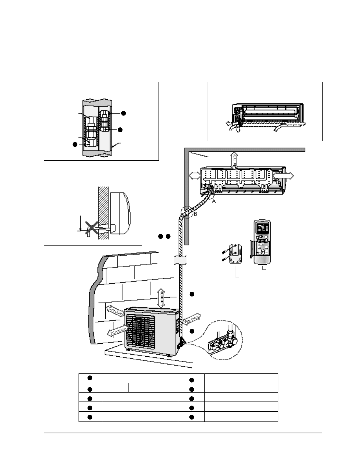
3-2-2 Installation diagram of indoor unit and outdoor unit
A Indoor unit gas leak test check point
Indoor unit
Piping
1
3
2
Tape vinyl
B Drain hose installation
Cut the piping hole
sloped slightly
5 6
250mm
or more
Piping may be laid to the rear, left,
right or down .
Right
Rear
Down
Rear
200mm or more
Left
1
2
3
4
5
Samsung Electronics
4
10
Piping (Liquid) 1/4" Clamper tube
7K/9K BTU Piping(Gas)3/8”
12K BTU Piping(Gas)1/2”
Installation tube Pipe-connection
Vinyl tape Screw
Putty Drain hose
6
7
8
9
10
Remote control
Remote control holder
Installation plate
3-5
 Loading...