

Page 1
QUESTIONS OR COMMENTS?
COUNTRY CALL OR VISIT US ONLINE AT
U.S.A
- Consumer
Electronics
- Mobile Phones
1-800-SAMSUNG (726-7864)
[HHP] 1-844-SAM-PAYS (726-7297)
www.samsung.com/us/support
CANADA 1-800-SAMSUNG(726-7864)
www.samsung.com/ca/support (English)
www.samsung.com/ca_fr/support (French)
Page 2

Air conditioner
User manual
AR77KSFP77
ŷ Thank you for purchasing this Samsung air conditioner.
ŷ Before operating this unit, please read this user manual carefully and retain it for future reference.
Page 3
2 English
Contents
Safety Information 4
Safety Information 4
At a Glance 12
Indoor Unit Overview 12
Display
Remote Control Overview 13
Inserting batteries
Remote Control Operation 14
2SHUDWLRQPRGHVŷ&RQWUROOLQJWHPSHUDWXUHŷ
&RQWUROOLQJIDQVSHHGŷ&RQWUROOLQJDLUIORZGLUHFWLRQ
Power Smart Features 16
Cooling Operation 16
&RROPRGHŷ6WHSFRROLQJIXQFWLRQ
Dehumidifying Operation 17
Dry mode
Air Purifying Operation 17
Virus doctor function
Heating Operation 18
Heat mode
Quick Smart Features 19
$XWRPRGHŷ)DQPRGHŷ)DVWIXQFWLRQŷ&RPIRUWIXQFWLRQŷ
%HHSVRXQGIXQFWLRQŷ4XLHWIXQFWLRQŷ
Energy-Saving Features 22
Energy-Saving Operation 23
6LQJOHXVHUIXQFWLRQŷ7LPHGRQ7LPHGRIIIXQFWLRQŷJRRGŰVOHHSIXQFWLRQ
Cleaning and Maintenance 25
Cleaning at a Glance 25
Troubleshooting 27
Page 4

3English
Installation 31
Safety Information on Installation 31
Preparation 33
Step 1.1 Choosing the installation location
Step 1.2 Checking and preparing accessories and tools
Step 1.3 Drilling a hole through the wall
Step 1.4 Taping the pipes, cables, and drain hose
Indoor Unit Installation 37
Step 2.1 Connecting the power and communication cables (assembly cable)
Step 2.2 Optional: Extending the power cable
Step 2.3 Installing and connecting the drain hose
Step 2.4 Optional: Extending the drain hose
Step 2.5 Optional: Changing the direction of the drain hose
Step 2.6 Installing and connecting the assembly pipes to the refrigerant pipes (assembly pipe)
Step 2.7 Shortening or extending the refrigerant pipes (assembly pipe)
Step 2.8 Fixing the installation plate
Outdoor Unit Installation 44
Step 3.1 Fixing the outdoor unit in place
Step 3.2 Connecting the power and communication cables and the refrigerant pipes
Step 3.3 Evacuating the air
Step 3.4 Adding refrigerant
Step 3.5 Important information regulation regarding the refrigerant used
Installation Inspection 48
Step 4.1 Performing the gas leak tests
Step 4.2 Performing final check and trial operation
Sub PCB installation(optional) 50
Wired remote controller installation (optional) 51
Page 5

4 English
Safety Information
Safety Information
Safety Information
WARNING
State of California Proposition 65 Warning (US only)
This product contains chemicals known to the State of California to
cause cancer and birth defects or other reproductive harm.
Before using your new air conditioner, please read this manual
thoroughly to ensure that you know how to safely and efficiently
operate the extensive features and functions of your new appliance.
Because the following operating instructions cover various models,
the characteristics of your air conditioner may differ slightly from
those described in this manual. If you have any questions, call your
nearest contact centre or find help and information online at www.
samsung.com.
WARNING
Hazards or unsafe practices that may result in severe personal
injury or death.
CAUTION
Hazards or unsafe practices that may result in minor personal
injury or property damage.
Follow directions. Do NOT attempt.
Make sure the machine is grounded to prevent electric shock.
Cut off the power supply. Do NOT disassemble.
FOR INSTALLATION
WARNING
Page 6
5English
Safety InformationSafety Information
Use a power cord with this product's power specifications
or higher and use the power cord for this appliance only. In
addition, do not use an extension cord.
ŷ Extending the power cord may result in electric shock or fire.
ŷ Do not use an electric transformer. This may result in electric
shock or fire.
ŷ If the voltage/frequency/rated current condition is different,
it may cause fire.
The installation of this appliance must be performed by a
qualified technician or service company.
ŷ Failing to do so may result in electric shock, fire, explosion,
problems with the product, or injury and may also void
warranty on the installed product.
Install an Isolation Switch next to the Air Conditioner (but
not on the panels of the Air Conditioner) and circuit breaker
dedicated to the air conditioner.
ŷ Failing to do so may result in electric shock or fire.
Fix the outdoor unit firmly so that the electric part of the
outdoor unit is not exposed.
ŷ Failing to do so may result in electric shock, fire, explosion,
or problems with the product.
Do not install this appliance near a heater, or inflammable material.
Do not install this appliance in a humid, oily or dusty location, in
a location exposed to direct sunlight and water (or rain). Do not
install this appliance in a location where gas may leak.
ŷ This may result in electric shock or fire.
Never install the outdoor unit in a location such as on a high
external wall where it could fall.
ŷ If the outdoor unit falls, it may result in injury, death or
Page 7
6 English
Safety Information
Safety Information
property damage.
This appliance must be properly grounded. Do not ground the
appliance to a gas pipe, plastic water pipe, or telephone line.
ŷ Failing to do so may result in electric shock, fire, and
explosion.
ŷ Make sure to use a socket-outlet with ground.
CAUTION
Please cover the air conditioner with PE BAG after installation,
and remove it when you start to run air conditioner.
Install your appliance on a level and hard floor that can
support its weight.
ŷ Failing to do so may result in abnormal vibrations, noise, or
problems with the product.
Install the drain hose properly so that water drains correctly.
ŷ Failing to do so may result in water overflowing and
property damage. Avoid adding drain to waste pipes as
odours may arise in the future.
When installing the outdoor unit, make sure to connect the
drain hose so that draining is performed correctly.
ŷ The water generated during heating by the outdoor unit may
overflow and result in property damage.
In particular, in winter, if a block of ice falls, it may result in
injury, death or property damage.
FOR POWER SUPPLY
WARNING
When the circuit breaker is damaged, contact your nearest
service centre.
Page 8

7English
Safety InformationSafety Information
Do not pull or excessively bend the power line. Do not twist
or tie the power line. Do not hook the power line over a metal
object, place a heavy object on the power line, insert the
power line between objects, or push the power line into the
space behind the appliance.
ŷ This may result in electric shock or fire.
CAUTION
When not using the air conditioner for a long period of time or
during a thunder/lightning storm, cut the power at the circuit
breaker.
ŷ Failing to do so may result in electric shock or fire.
FOR USING
WARNING
If the appliance is flooded, please contact your nearest service
centre.
ŷ Failing to do so may result in electric shock or fire.
If the appliance generates a strange noise, a burning smell or
smoke, cut off the power supply immediately and contact the
nearest service centre.
ŷ Failing to do so may result in electric shock or fire.
In the event of a gas leak (such as propane gas, LP gas, etc.),
ventilate immediately without touching the power line. Do not
touch the appliance or power line.
ŷ Do not use a ventilating fan.
ŷ A spark may result in an explosion or fire.
To reinstall the air conditioner, please contact your nearest
service centre.
Page 9
8 English
Safety Information
Safety Information
ŷ Failing to do so may result in problems with the product,
water leakage, electric shock, or fire.
ŷ Delivery service for the product is not provided. If you
reinstall the product in another location, additional
construction expenses and an installation fee will be charged.
ŷ Especially, when you wish to install the product in an
unusual location such as in an industrial area or near the
seaside where it is exposed to salt in the air, please contact
your nearest service centre.
Do not touch the circuit breaker with wet hands.
ŷ This may result in electric shock.
Do not turn the air conditioner off with the circuit breaker
while it is operating.
ŷ Turning the air conditioner off and then on again with the
circuit breaker may cause a spark and result in electric shock
or fire.
After unpacking the air conditioner, keep all packaging
materials well out of the reach of children, as packaging
materials can be dangerous to children.
ŷ If a child places a bag over its head, it may result in
suffocation.
Do not touch the air flow blade with your hands or fingers
during heating.
ŷ This may result in electric shock or burns.
Do not insert your fingers or foreign substances into the air
inlet/outlet of the air conditioner.
ŷ Take special care that children do not injure themselves by
inserting their fingers into the product.
Do not strike or pull the air conditioner with excessive force.
Page 10
9English
Safety InformationSafety Information
ŷ This may result in fire, injury, or problems with the product.
Do not place an object near the outdoor unit that allows
children to climb onto the machine.
ŷ This may result in children seriously injuring themselves.
Do not use this air conditioner for long periods of time in badly
ventilated locations or near infirm people.
ŷ Since this may be dangerous due to a lack of oxygen, open a
window at least once an hour.
If any foreign substance such as water has entered the
appliance, cut off the power supply and contact the nearest
service centre.
ŷ Failing to do so may result in electric shock or fire.
Do not attempt to repair, disassemble, or modify the appliance
yourself.
ŷ Do not use any fuse (such as cooper, steel wire, etc.) other
than the standard fuse.
ŷ Failing to do so may result in electric shock, fire, problems
with the product, or injury.
CAUTION
Do not place objects or devices under the indoor unit.
ŷ Water dripping from the indoor unit may result in fire or
property damage.
Check that the installation frame of the outdoor unit is not
broken at least once a year.
ŷ Failing to do so may result in injury, death or property
damage.
Max current is measured according to IEC standard for safety
and current is measured according to ISO standard for energy
Page 11
10 English
Safety Information
Safety Information
efficiency.
Do not stand on top of the appliance or place objects (such as
laundry, lighted candles, lighted cigarettes, dishes, chemicals,
metal objects, etc.) on the appliance.
ŷ This may result in electric shock, fire, problems with the
product, or injury.
Do not operate the appliance with wet hands.
ŷ This may result in electric shock.
Do not spray volatile material such as insecticide onto the
surface of the appliance.
ŷ As well as being harmful to humans, it may also result in
electric shock, fire or problems with the product.
Do not drink the water from the air conditioner.
ŷ The water may be harmful to humans.
Do not apply a strong impact to the remote control and do not
disassemble the remote control.
Do not touch the pipes connected with the product.
ŷ This may result in burns or injury.
Do not use this air conditioner to preserve precision
equipment, food, animals, plants or cosmetics, or for any other
unusual purposes.
ŷ This may result in property damage.
Avoid directly exposing humans, animals or plants to the air
flow from the air conditioner for long periods of time.
ŷ This may result in harm to humans, animals or plants.
This appliance is not intended for use by persons (including
children) with reduced physical, sensory or mental capabilities,
or lack of experience and knowledge, without supervision
Page 12

11English
Safety InformationSafety Information
or instruction concerning use of the appliance by a person
responsible for their safety. Children should be supervised to
ensure that they do not play with the appliance.
FOR CLEANING
WARNING
Do not clean the appliance by spraying water directly onto it.
Do not use benzene, thinner or alcohol to clean the appliance.
ŷ This may result in discolouration, deformation, damage,
electric shock or fire.
Before cleaning or performing maintenance, cut off the
power supply and wait until the fan stops.
ŷ Failing to do so may result in electric shock or fire.
CAUTION
Take care when cleaning the surface of the heat exchanger of
the outdoor unit since it has sharp edges.
ŷ This should be done by a qualified technician. Please
contact your installer or service centre.
Do not clean the inside of the air conditioner by yourself.
ŷ For cleaning inside the appliance, contact your nearest
service centre.
ŷ When cleaning the filter, refer to the descriptions in the
ů&OHDQLQJDWD*ODQFHŰVHFWLRQ
ŷ Failing to do so may result in damage, electric shock or fire.
Page 13
12 English
At a Glance
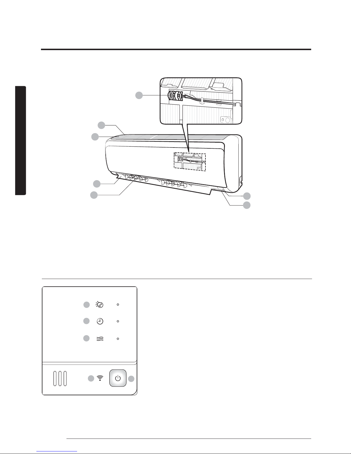
The actual product may differ slightly from the image depicted below.
Indoor Unit Overview
03
04
01
02
06
07
05
01 Air intake
02 Air filter
03 Air flow blade (up and down)
04 Air flow blade (left and right)
05 Room temperature sensor
06 Display
07 Power button /
Remote control receiver
Display
01
02
03
04
05
01 good'sleep indicator
02 Timer indicator
Auto clean indicator
03 Operation indicator
04 Power button
05 Remote controller receiver
Page 14

13English
At a Glance
Remote Control Overview
01 Set temperature indicator
02 Timer option indicator
03 Operation mode indicator
04 Options indicator
05 Low battery indicator
06 Transmit indicator
07 Fan speed indicator
08 Vertical air swing indicator
09 Horizontal air swing indicator (Without this
function)
10 Settings indicator
11 Power button
12 Temperature button
13 Options button
14 Timer button
15 Direction button / Selection button
16 Vertical air swing button
17 Mode button
18 Fan speed button
19 Horizontal air swing button(Without this
function)
20 Settings button
21 SET button
NOTE
ŷ The descriptions in this manual are primarily
made based on the remote control buttons.
ŷ Although Virus Doctor(
)/d'light Cool /
Usage / Filter Reset / Display / Horizontal
air swing indicator is displayed on the
remote control display, it is not available on
this model.
01
05
06
07
08
10
09
16
17
18
20
21
02
03
04
11
12
13
19
14
15
Inserting batteries
two 1.5V AAA type batteries
Page 15
14 English
At a Glance
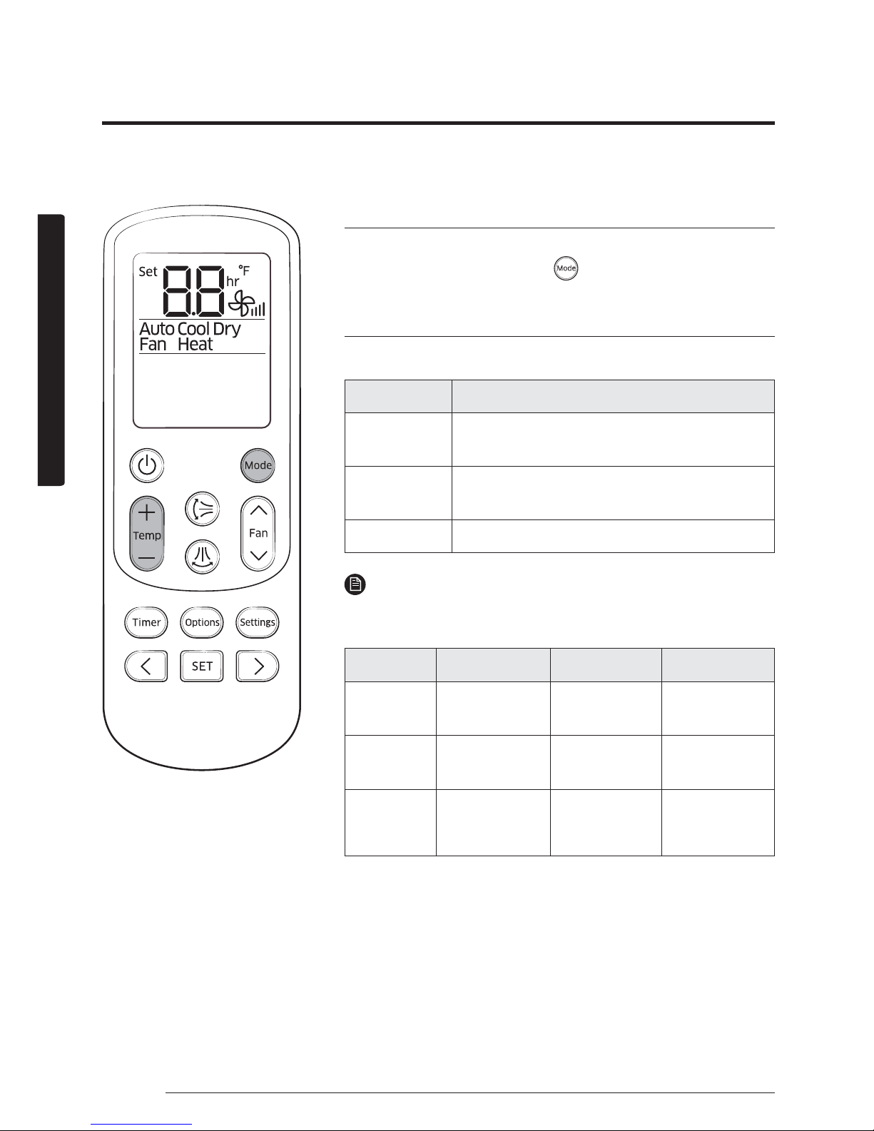
Operation modes
You can change the current mode between Auto, Cool, Dry,
Fan, and Heat by pressing the
button.
Controlling temperature
You can control the temperature in each mode as follows:
Mode Temperature control
Auto/Cool/
Heat
Adjust by 1 °F between 61°F and 86°F(16°C
and 30°C)
Dry
Adjust by 1 °F between 65°F and 86°F(18°C
and 30°C)
Fan You cannot control the temperature.
NOTE
You can use the Cool, Dry, and Heat modes in the following
conditions:
Mode Cool Dry Heat
Indoor
temperature
61˚F to 90˚F
(16 °C to 32 °C)
65˚F to 90˚F
(18 °C to 32 °C)
81°F(27 °C)
or less
Outdoor
temperature
14°F to 114°F
(-10 °C to 46 °C)
14°F to 114°F
(-10 °C to 46 °C)
5°F to 75°F
(-15 °C to 24 °C)
Indoor
humidity
80% or less
relative
humidity
__
ŷ If the air conditioner operates in a high humidity
environment in the Cool mode for an extended period of
time, condensation may occur.
ŷ If the outdoor temperature drops to 23°F(-5°C), the heating
capacity may decrease to as much as 60% to 70% of the
specified capacity.
You can use the air conditioner easily by selecting a mode and then by controlling the
temperature, fan speed, and air direction.
Remote Control Operation
Page 16

15English
At a Glance
Controlling fan speed
You can select the following fan speeds in each mode:
Mode Available fan speeds
Auto/Dry
(Auto)
Cool/Heat
(Auto), (Low), (Med), (High),
(Turbo)
Fan
(Low), (Med), (High), (Turbo)
Controlling air flow direction
Keep the vertical air flow in a constant direction by stopping
the movements of the vertical air flow blade.
In operation
Ź
NOTE
ŷ If you adjust the vertical air flow blade manually, it may
not close completely when you turn off the air conditioner.
ŷ You can control the vertical air flow direction when the
good'sleep function is running while in the Heat mode, but
not while in the Cool mode.
Horizontal air flow (manual)
Keep the horizontal air flow in a constant direction by
changing the directions of the horizontal air flow blades
manually.
CAUTION
ŷ To prevent personal injury, make sure
that you change the directions of the
horizontal air flow blades after stopping
the movements of the vertical air flow
blade.
Page 17
16 English
Power Smart Features
The smart and powerful cooling functions of the Samsung air conditioner keep an enclosed space
cool and comfortable.
Cooling Operation
Cool mode
Use the Cool mode to stay cool in hot weather.
Ź Ź
Select Cool.
NOTE
ŷ For comfort, keep the temperature difference between the
indoor and outdoor air within 9°F(5 °C) in the Cool mode.
ŷ After selecting the Cool mode, select a function,
temperature, and fan speed that you want to apply.
– To cool your room quickly, select a low temperature and
a strong fan speed.
– To save energy, select a high temperature and a weak
fan speed.
– As the indoor temperature approaches the set
temperature, the compressor will operate at a low speed
to save energy.
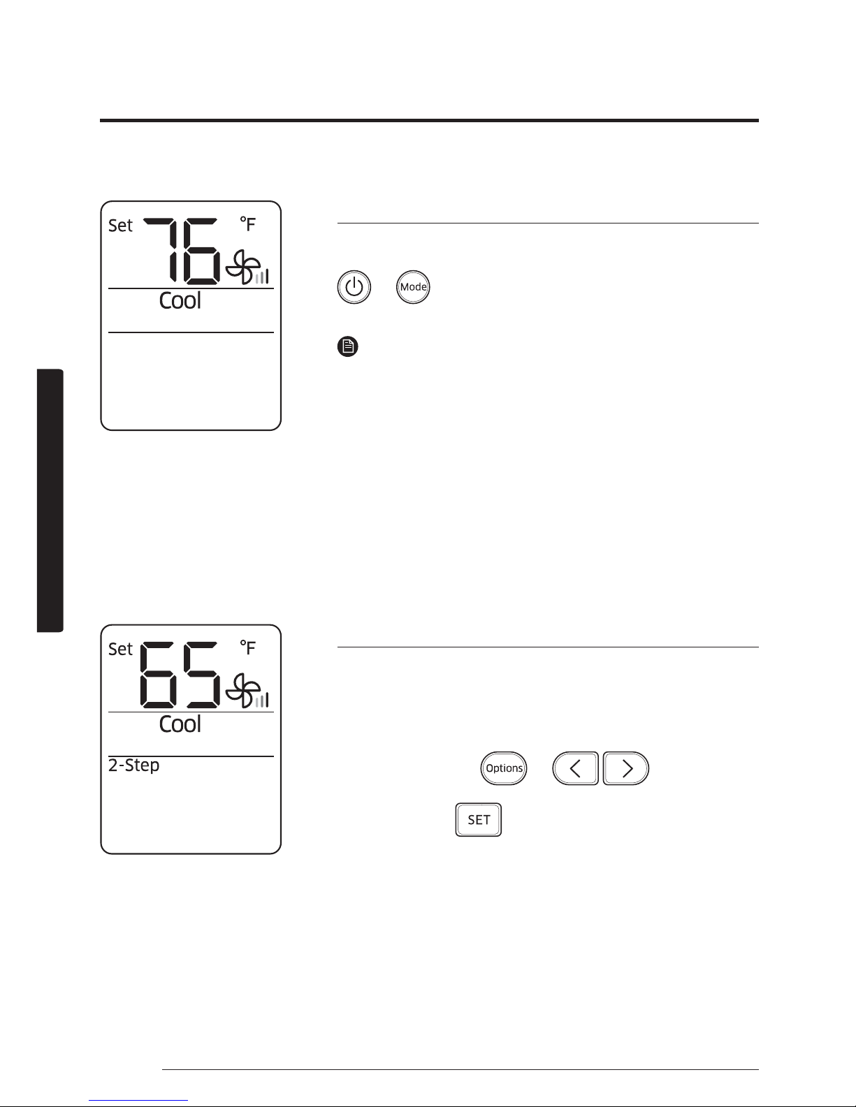
2-Step cooling function
Use the 2-Step cooling function to quickly reach the set
temperature. The air conditioner automatically adjusts the fan
speed and air flow direction. You can select this function only
when the Cool mode is running.
In the Cool mode
Ź Ź Ź
Select 2-Step.
Ź
Page 18
17English
Power Smart Features
The dehumidifying function of the Samsung air conditioner keeps an enclosed space dry and
comfortable.
Dehumidifying Operation
Dry mode
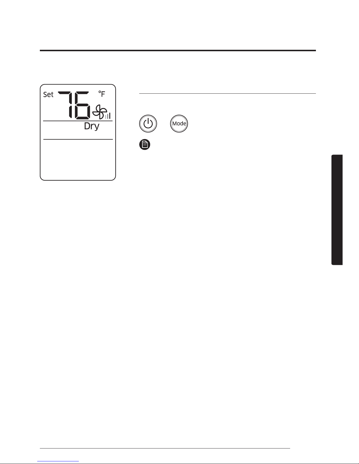
Use the Dry mode in rainy or humid weather.
Ź Ź
Select Dry.
NOTE
ŷ The lower the set temperature is, the greater the
dehumidifying capacity is. When the current humidity
seems to be high, adjust the set temperature to a low
temperature.
ŷ You cannot use the Dry mode for heating. The Dry mode is
designed to produce a cooling side-effect.
Page 19
18 English
Power Smart Features
Heat mode
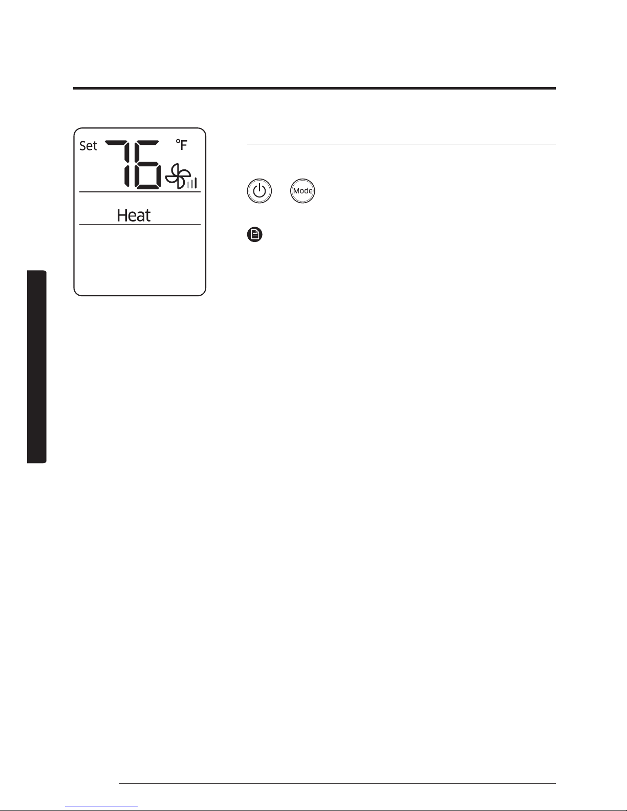
Use the Heat mode to stay warm.
Ź Ź
Select Heat.
NOTE
ŷ While the air conditioner warms up, the fan may not
operate for about 3 to 5 minutes at the beginning to
prevent cold blasts.
ŷ If the air conditioner heats insufficiently, use an additional
heating appliance in combination with the air conditioner.
ŷ When the outdoor temperature is low and the humidity is
high in Heat mode, frost may develop on the outdoor heat
exchanger. This may also decrease the heating efficiency.
If this occurs, the air conditioner runs the defrost function
for 5 to 12 minutes to remove frost from the outdoor heat
exchanger.
ŷ When the defrost function is running, steam is produced
on the outdoor unit. The air conditioner moves the vertical
air flow blade to the lowest position, as shown in the
left figure, to prevent cold air from coming out from the
indoor unit.
A. The position of the vertical air flow blade when the
defrost function is running (The blade looks almost closed.)
B. The position range of the vertical air flow blade when
the Heat mode is running.
ŷ When the defrost function is running, no air comes out
from the indoor unit in order to prevent cold air from
coming out. When the defrost function is finished, warm
air comes out after a while.
ŷ The cycle of the defrost function may be shortened
depending on the amount of frost on the outdoor unit.
ŷ The cycle of the defrost function may be shortened
depending on the humidity from rain and snow, too.
ŷ When the defrost function is running, you cannot select
other functions with the remote control. Select them after
the defrost function is finished.
The heating functions of the Samsung air conditioner keep an enclosed space warm and
comfortable.
Heating Operation
Page 20
19English
Power Smart Features
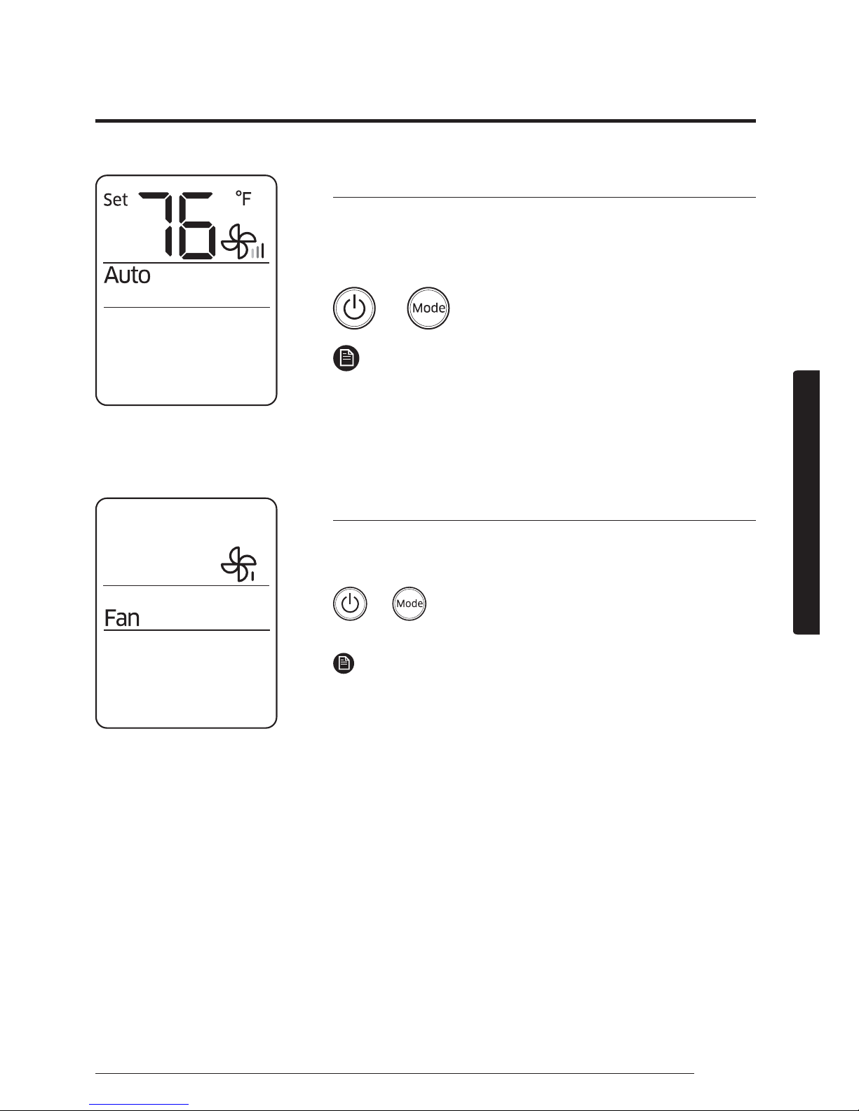
Auto mode
Use the Auto mode when you want the air conditioner to
automatically control the operation. The air conditioner will
provide the most comfortable atmosphere that it can.
Ź Ź
Select Auto.
NOTE
ŷ When the indoor temperature seems to be higher
or lower than the set point, the air conditioner
automatically produces either cool air to cool down the
indoor temperature or warm air to warm up the indoor
temperature.
Fan mode
Use the Fan mode to run the air conditioner like a common
fan. The air conditioner provides a natural breeze.
Ź Ź
Select Fan.
NOTE
ŷ If the air conditioner will not be used for an extended
period of time, dry the air conditioner by running it in the
Fan mode for 3 or 4 hours.
ŷ The outdoor unit is designed not to operate in the Fan
mode to prevent cold air from entering through the unit.
This is a normal operation and not a fault with the air
conditioner.
There is a variety of extra functionality provided by the Samsung air conditioner.
Quick Smart Features
Page 21
20 English
Power Smart Features
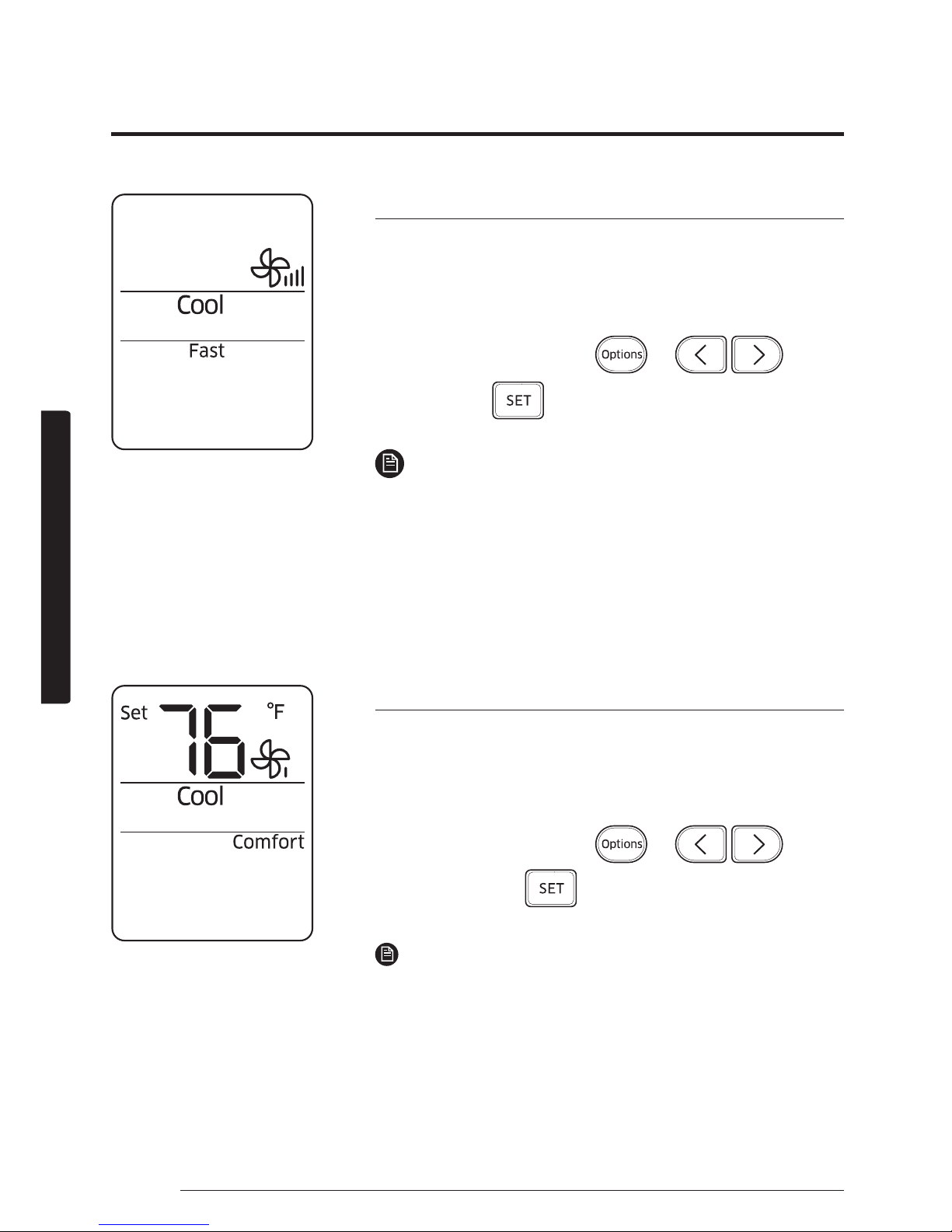
Fast function
Use the Fast function to quickly cool or heat your room. This
function is the most powerful cooling and heating function
provided by the air conditioner. You can select this function
both in the Cool and Heat modes.
In the Cool or Heat mode
Ź Ź Ź
Select Fast.
Ź
NOTE
ŷ If you select the Fast function while such functions as
2-Step cooling, Comfort, Single user, Quiet, or good'sleep
are running, these functions are cancelled.
ŷ You can change the air flow direction.
ŷ You cannot change the set temperature and the fan speed.
ŷ When you select the Fast function in the Heat mode, you
may not be able to increase the fan speed in order to
prevent cool air from blowing.
Comfort function
Use the Comfort function when you feel the current cooling
or heating effect is too strong. The air conditioner provides a
mild cooling or heating. You can select this function both in
the Cool and Heat modes.
In the Cool or Heat mode
Ź Ź Ź
Select Comfort.
Ź
NOTE
ŷ You can change the set temperature and the air flow direction.
ŷ You cannot change the fan speed.
ŷ If you select the Comfort function while such functions as
2-Step cooling, Fast, Single user, Quiet, or good'sleep are
running, these functions are cancelled.
ŷ If you feel cooling or heating effect in the Comfort
function is weak, cancel the Comfort function.
Page 22
21English
Power Smart Features
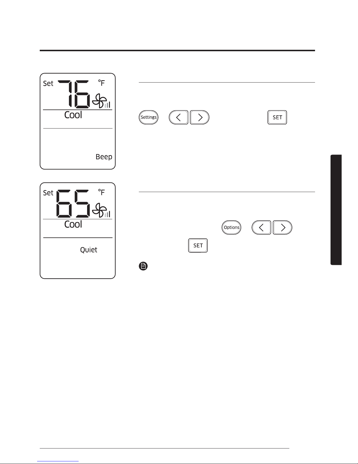
Beep sound function
Use the Beep sound function to turn on or off the beep sound
that plays when you press a button on the remote control.
Ź Ź
Select Beep.
Ź
Quiet function
Use the Quiet function to reduce operating noise. You can
select this function both in the Cool and Heat modes.
In the Cool or Heat mode
Ź Ź Ź
Select Quiet.
Ź
NOTE
ŷ You can change the set temperature and the air flow
direction.
ŷ You cannot change the fan speed.
ŷ If you select the Quiet function while such functions as
2-Step cooling, Fast, Comfort, Single user, or good'sleep
are running, these functions are cancelled.
Page 23
22 English
Energy-Saving Features
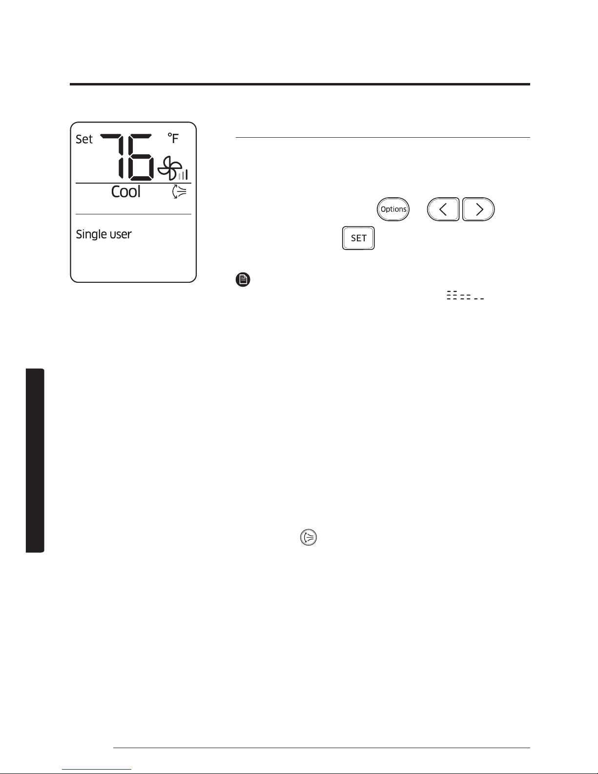
Single user function
Use the Single user function to reduce electricity consumption
while staying cool or warm. You can select this function in the
Cool and Heat modes.
In the Cool or Heat mode
Ź Ź Ź
Select Single user.
Ź
NOTE
ŷ When the Single user function starts, the
pattern
appears on the remote control for a few seconds, and
vertical air swing begins automatically.
ŷ If you select the Single user while such function as 2-Step
cooling, Fast, Comfort, Quiet, or good'sleep are running,
these modes are cancelled.
ŷ After selecting the Single user function, you can change
the set temperature (76 °F to 86°F(24 °C to 30 °C) in the
Cool mode, 61 °F to 86°F(16 °C to 30 °C)in the Heat mode),
fan speed, and vertical air flow direction.
ŷ When the Single user function is turned on in the Cool
mode while the set temperature is set to lower than 76
°F(24 °C), the set temperature is automatically raised to 76
°F(24 °C). But if the set temperature is set to between 77°F
and 86°F(25 °C and 30 °C), it remains the same.
ŷ Even after you turn off the Single user function, vertical
air swing continues until you turn it off with the Vertical
air swing (
) button.
Energy-Saving Operation
Page 24
23English
Energy-Saving Features
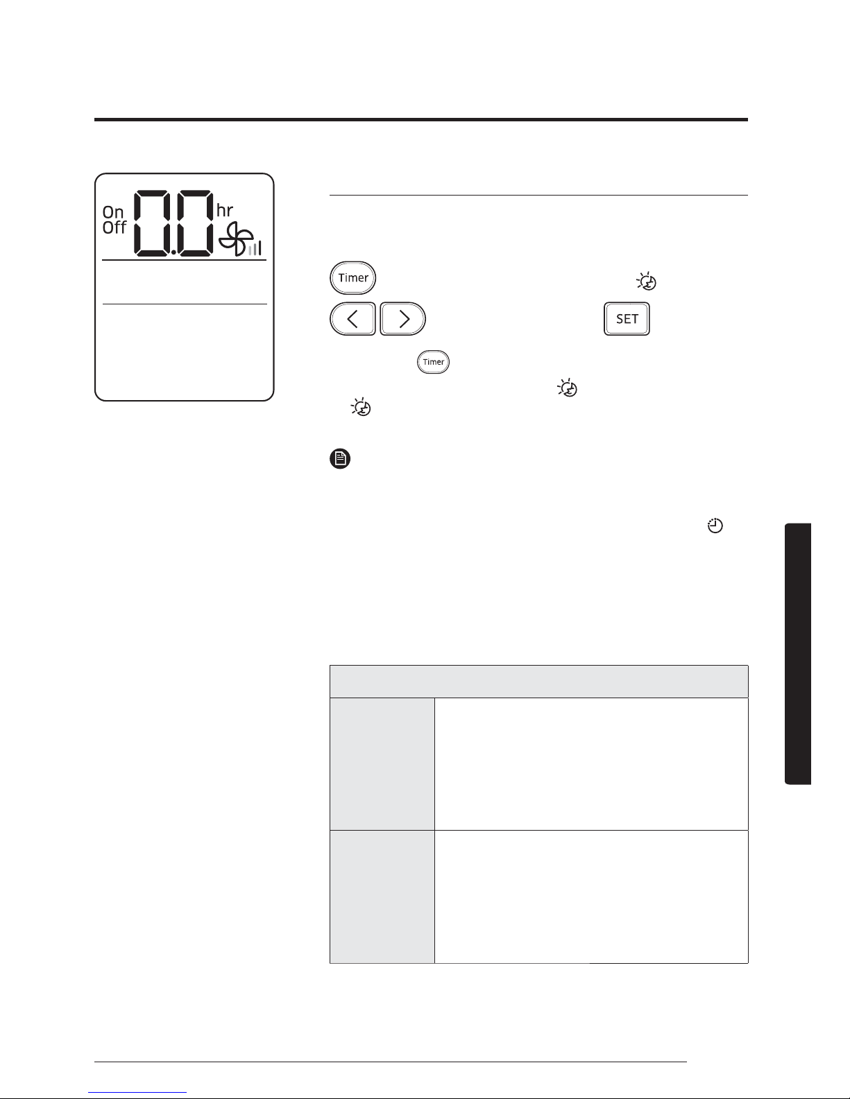
Timed on/Timed off function
Use the Timed on/Timed off to turn on or off the air
conditioner after the time that you set.
(Select On or Off among On, Off, and .)
Ź
(Set the on/off time.)
Ź
ŷ Press the (Timer) button to change the current
function between On, Off, and
JRRGŰVOHHS
JRRGŰVOHHSLVGLVSOD\HGLQWKH&RRODQG+HDWPRGHV
only.
NOTE
ŷ You can set a time between 0.5 and 24 hours. Set the time
interval to 0.0 to cancel the Timed on/off function.
ŷ Once you start the Timed on/off function, the Timer (
)
indicator is displayed on the indoor unit display.
ŷ After starting the Timed on function, you can change the
mode and the set temperature. You cannot change the set
temperature while the Fan mode is running.
ŷ You cannot set the same time for both of the Timed on
and Timed off functions.
Combining Timed on and Timed off
When
the air
conditioner
is off
Example) Timed on: 3 hours, Timed off: 5
hours
The air conditioner turns on after 3 hours
from the moment you start Timed on/
off, remains on for 2 hours, then turns off
automatically.
When
the air
conditioner
is on
Example) Timed on: 3 hours, Timed off: 1
hour
The air conditioner turns off after 1 hour
from the moment you start Timed on/
off, then turns on after 2 hours from the
moment it is turned off.
Page 25
24 English
Energy-Saving Features
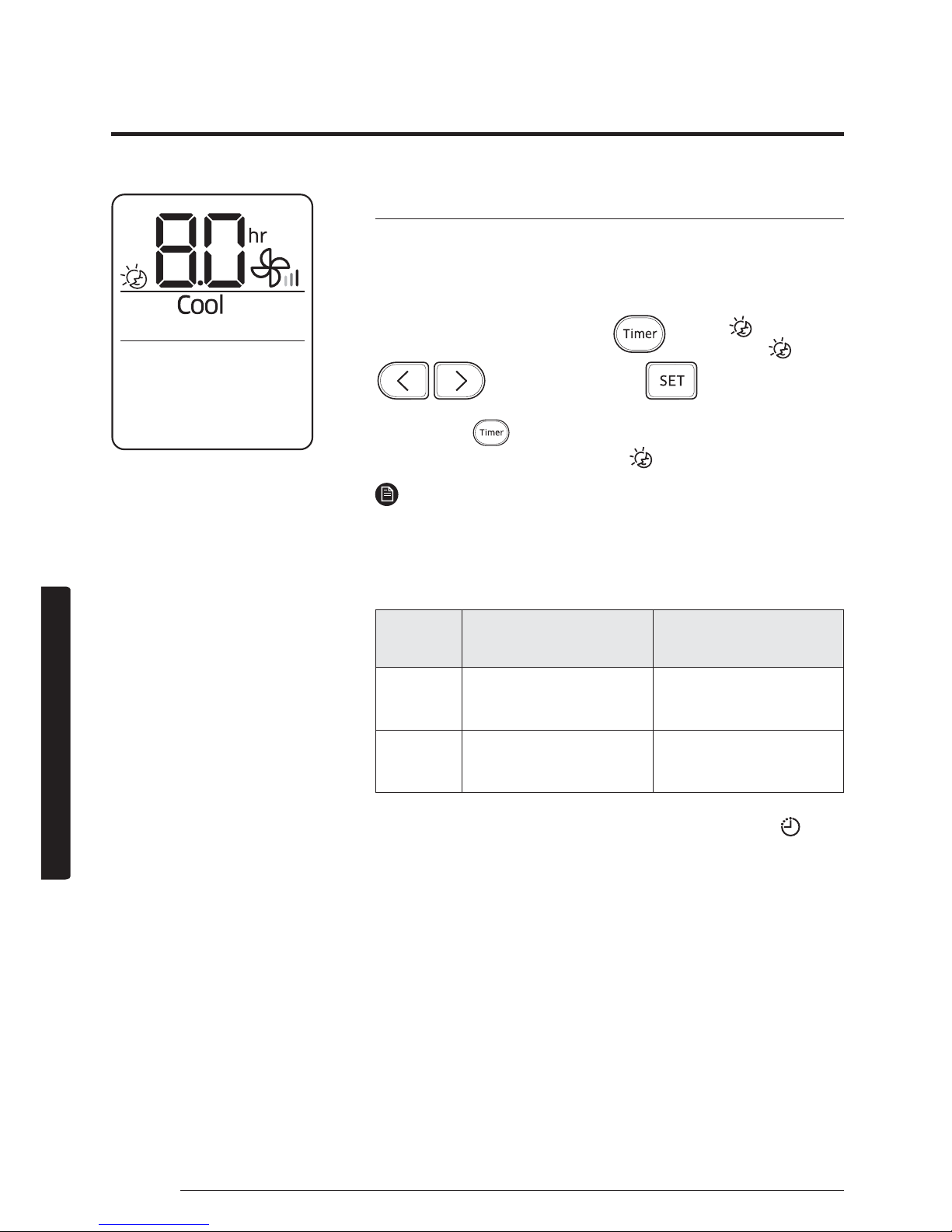
good’sleep function
Use the good'sleep function to get a good sleep at night and
to save energy. You can select this function both in the Cool
and Heat modes.
In the Cool or Heat mode
Ź
(Select among
On, Off, and
.)
Ź
(Set the
operation time.)
Ź
ŷ Press the (Timer) button to change the current
function between On, Off, and
JRRGŰVOHHS
NOTE
ŷ You can adjust the set temperature by 1 °F between 61°F
and 86°F(16°C and 30°C)
ŷ The recommended and optimal set temperatures in the
JRRGŰVOHHSIXQFWLRQDUHDVIROORZV
Mode
Recommended set
temperature
Optimal set
temperature
Cool
77 °F to 81 °F
(25 °C to 27 °C)
79 °F (26 °C)
Heat
70 °F to 73 °F
(21 °C to 23 °C)
72 °F(22 °C)
ŷ 2QFH\RXVWDUWWKHJRRGŰVOHHSIXQFWLRQWKH7LPHU
)
indicator appears on the indoor unit display.
ŷ You can set the operation time to between 0.5 and
12 hours. Set the operation time to 0.0 to cancel the
JRRGŰVOHHSIXQFWLRQ
ŷ 7KHGHIDXOWRSHUDWLRQWLPHIRUWKHJRRGŰVOHHSIXQFWLRQLQ
the Cool mode is 8 hours. If the operation time is set to
over 5 hours, the Wake up function begins 1 hour before
the set time. The air conditioner stops automatically when
the operation time expires.
ŷ When the Timed on, Timed off, and good'sleep functions
are overlapped, the air conditioner operates its timer with
only the function that you have started most recently.
Page 26
25English
Cleaning and Maintenance
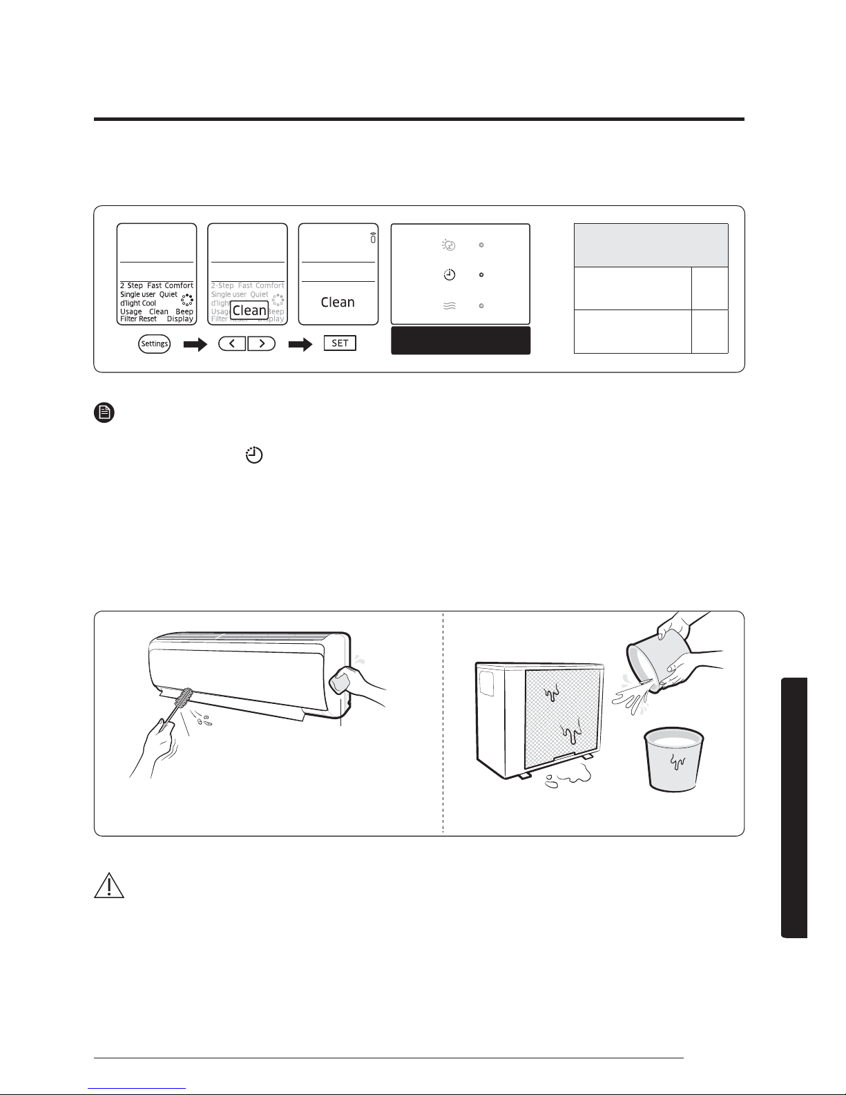
Running Auto clean
Indoor unit display
NOTE
ŷ When you set the Auto clean timer, Clean blinks and then disappears on the remote control
display. The Timer (
) indicator also appears on the indoor unit display.
ŷ When the air conditioner is off, Auto clean starts immediately when it is selected. When the
air conditioner is on, Auto clean starts as soon as the air conditioner stops running.
ŷ During Auto clean, the indoor fan continues to run, and air flow blades remain open to expel
ambient air.
Cleaning the indoor unit exterior and outdoor unit heat exterior
CAUTION
ŷ Do not clean the display by using alkaline detergent.
Cleaning at a Glance
Cleaning duration
(minutes)
Auto (Cool),
Cool, Dry
30
Auto (Heat),
Heat, Fan
15
Soft brush
Tepid damp cloth
Before cleaning, be sure to turn off the equipment
and disconnect the power plug.
Spray water to clean the dust.
Page 27
26 English
Cleaning and Maintenance
ŷ Do not use sulphuric acid, hydrochloric acid, or organic solvents
(such as thinner, kerosene, and acetone) to clean the surfaces. Do
not put any stickers on it as this can damage the surface of the
air conditioner.
ŷ When you clean and inspect the heat exchanger on the outdoor
unit, contact the local service centre for help.
ŷ Make sure to prevent any injury from sharp edges of the surface
when handling the heat exchanger.
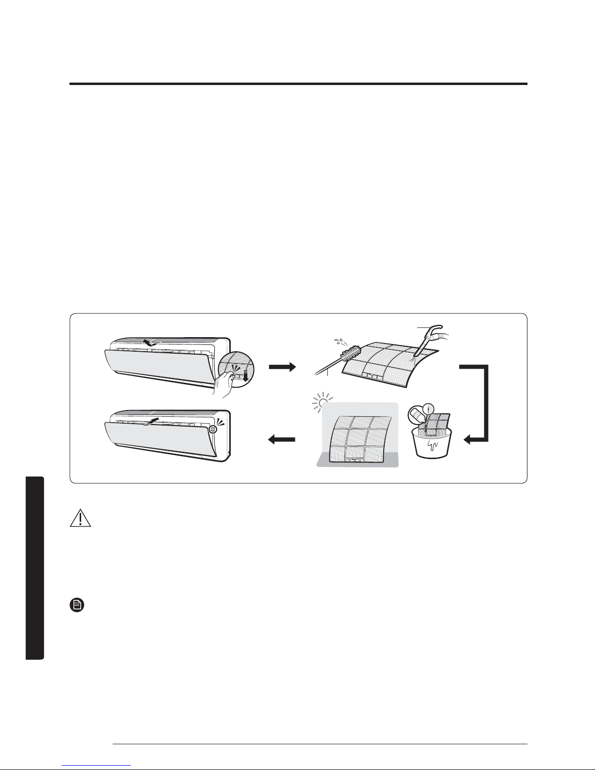
Cleaning the filter
CAUTION
ŷ Do not scrub the air filter with a brush or other cleaning utensil.
This may damage the filter.
ŷ Do not expose the air filter to direct sunlight when drying it.
NOTE
ŷ Clean the air filter every 2 weeks. Cleaning term may vary depending on the usage and
environmental conditions.
ŷ If the air filter dries in a humid area, it may produce offensive odours. Clean it again and dry
it in a well-ventilated area.
Vacuum cleaner
Soft brush
30 minutes
Mild detergent
Page 28
27English
Cleaning and Maintenance
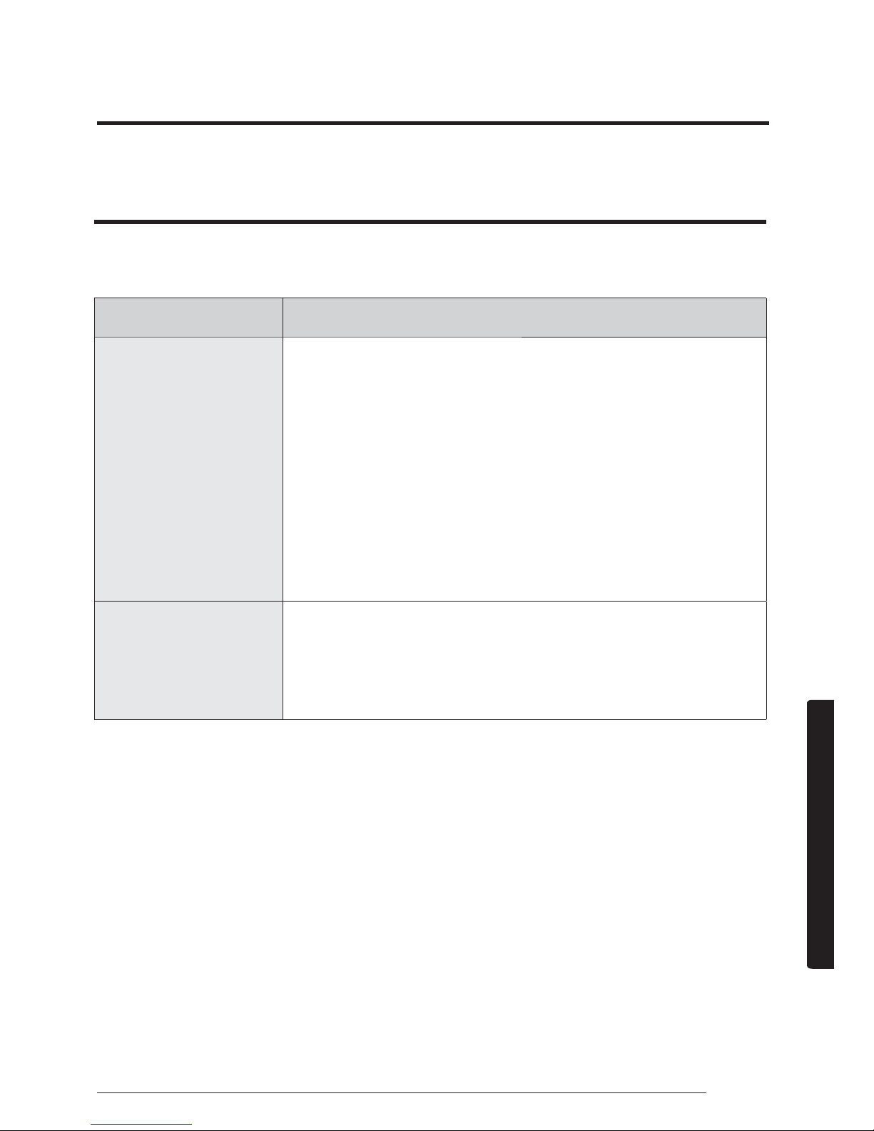
If the air conditioner operates abnormally, refer to the following
chart to save time and unnecessary expenses.
Problem Solution
The air
conditioner does
not work at all.
ŷ Check the power status, then operate the air
conditioner again.
ŷ Switch on the circuit breaker, plug in the
power cord, then operate the air conditioner
again.
ŷ Make sure that the isolator is turned on.
ŷ Check whether the Timed off function is
running. Operate the air conditioner again by
pressing the Power button.
I cannot change
the temperature.
ŷ Check whether the Fan or Fast mode is
running. In these modes, the air conditioner
controls the set temperature automatically,
and you cannot change the set temperature.
Troubleshooting
Page 29
28 English
Cleaning and Maintenance
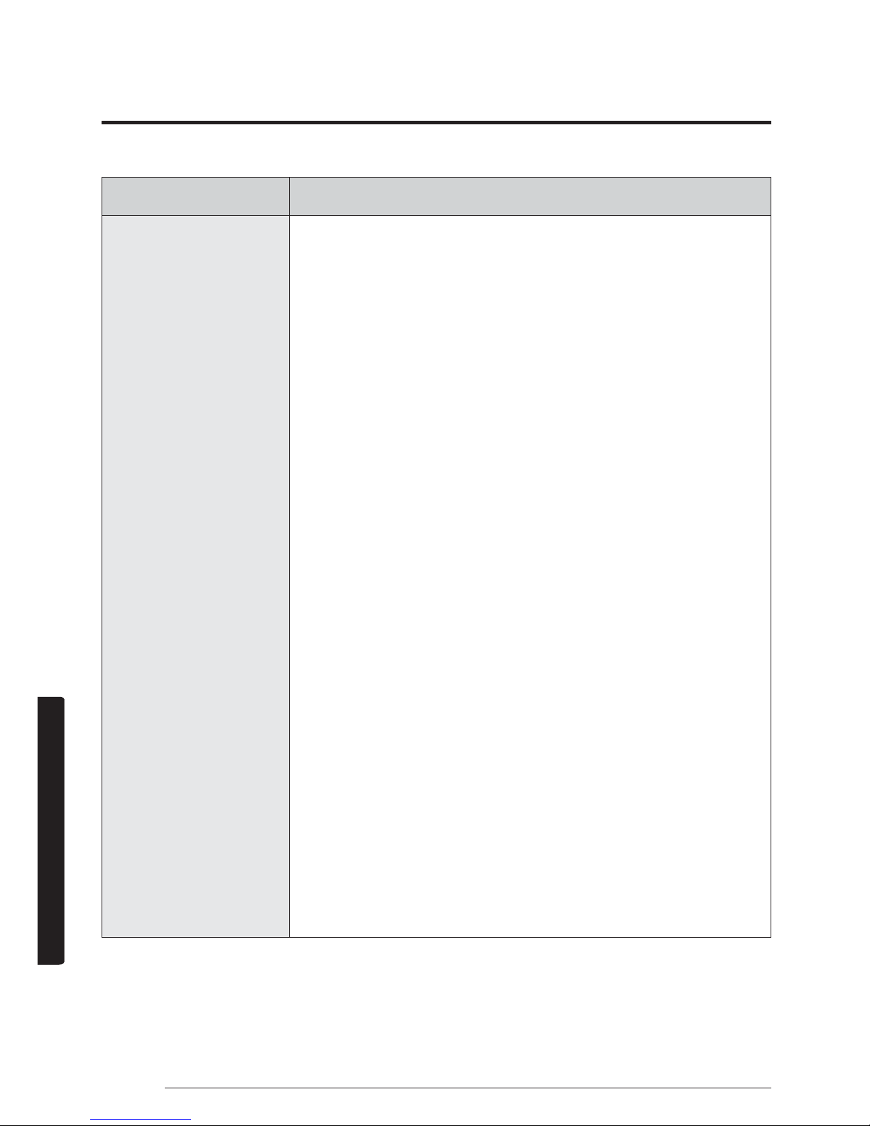
Problem Solution
Cool or warm air
does not come
out of the air
conditioner.
ŷ Check whether the set temperature is higher
in the Cool mode or lower in the Heat mode
than the current temperature. Press the
Temperature button on the remote control to
change the set temperature.
ŷ Check whether the air filter is blocked with
dirt. If the air filter is blocked, the cooling
and heating performance may decrease.
Remove dirt regularly.
ŷ Check whether the outdoor unit is covered
or installed near obstacles. Remove the
coverings and obstacles.
ŷ Check whether the air conditioner is running
the defrost function. When ice forms in
winter or the outdoor temperature is too low,
the air conditioner runs the defrost function
automatically. While this function is running,
the indoor fan stops and warm air does not
come out.
ŷ Check whether doors or windows are open.
This may cause poor cooling or heating
performance. Close the doors and windows.
ŷ Check whether the air conditioner is turned
on immediately after the cooling or heating
operation stops. In this case, only the fan
runs to protect the outdoor unit compressor.
Page 30
29English
Cleaning and Maintenance
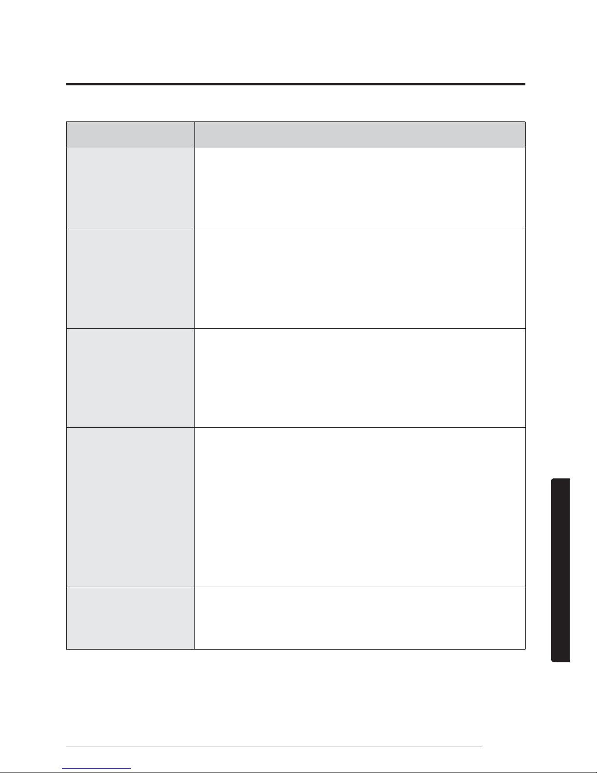
Problem Solution
Cool or warm air
does not come
out of the air
conditioner.
ŷ Check whether the pipe length is too long.
When the pipe length exceeds the maximum
pipe length, the cooling and heating
performance may decrease.
I cannot change
the air flow
direction.
ŷ Check whether the good'sleep function is
running. While this function is running, you
cannot control the air flow direction. (But
you can control the air flow direction if this
function is running in the Heat mode.)
I cannot change
the fan speed.
ŷ When the Auto, Dry, or Fast mode is running
or the good'sleep function is running in the
Cool mode, the air conditioner controls the
fan speed automatically and you cannot
change the fan speed.
The remote
control does not
work.
ŷ Replace the batteries in the remote control
with new ones.
ŷ Make sure that nothing is blocking the
remote control sensor.
ŷ Check whether there are strong lighting
apparatus near the air conditioner. Strong
light which comes from fluorescent bulbs or
neon signs may interrupt the electric waves.
The Timed on/
off function
does not work.
ŷ Check whether you pressed the SET button
on the remote control after setting the time.
Page 31
30 English
Cleaning and Maintenance
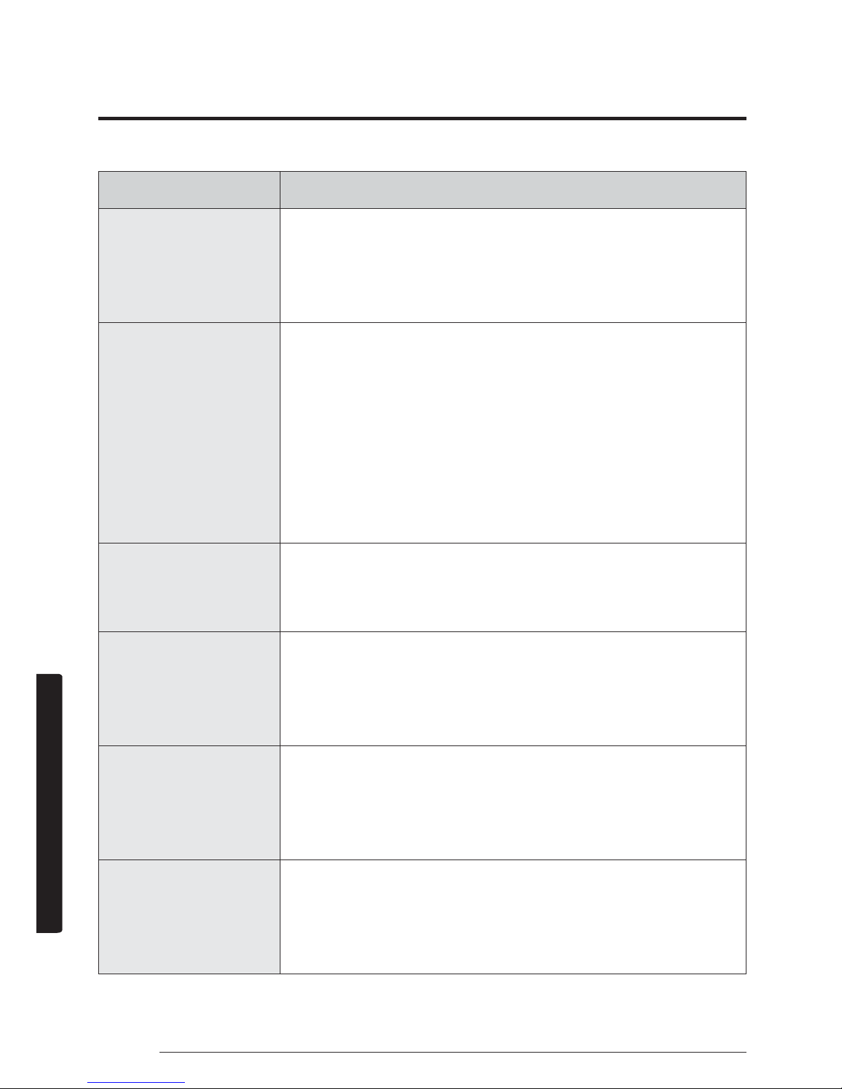
Problem Solution
The indicator
blinks
continuously.
ŷ Press the Power button to turn off the air
conditioner or disconnect the power plug.
If the indicator is still blinking, contact the
service centre.
Odours
permeate in the
room during
operation.
ŷ Check whether the air conditioner is
running in a smoky area. Ventilate the
room or operate the air conditioner in the
Fan mode for 3 to 4 hours. (There are no
components used in the air conditioner that
emit a strong odour.)
ŷ Check whether the drains are clean. Clean
them regularly.
An error is
indicated.
ŷ If the indoor unit indicator blinks, contact
the nearest service centre. Be sure to pass
the error code to the service centre.
Noise is
generated.
ŷ When refrigerant flow changes, noise may
be generated, depending on the status
of the air conditioner. This is a normal
operation.
Smoke is
generated from
the outdoor unit.
ŷ If may not be a fire but it can be a steam
generated from the outdoor heat exchanger
while the defrost function is running in the
Heat mode in winter.
Water drops
from the pipe
connections of
the outdoor unit.
ŷ Condensation may develop when the
ambient temperature changes excessively.
This is a normal operation.
Page 32
31English
Installation
Carefully follow the precautions listed below because
they are essential to guarantee the safety of both the air
conditioner and the workers.
ŷ Always disconnect the air conditioner from the power
supply before servicing it or accessing its internal
components.
ŷ Verify that installation and testing operations are
performed by qualified personnel.
ŷ Verify that the air conditioner is not installed in an
easily accessible area.
General information
ŷ Carefully read the content of this manual before
installing the air conditioner and store the manual in a
safe place in order to be able to use it as reference after
installation.
ŷ For maximum safety, installers should always carefully
read the following warnings.
ŷ Store the operation and installation manual in a safe
location and remember to hand it over to the new
owner if the air conditioner is sold or transferred.
ŷ This manual explains how to install an indoor unit
with a split system with two SAMSUNG units. The use
of other types of units with different control systems
may damage the units and invalidate the warranty.
The manufacturer shall not be responsible for damages
arising from the use of non compliant units.
ŷ The manufacturer shall not be responsible for damage
originating from unauthorised changes or the improper
connection of electric and requirements set forth in the
“Operating limits” table, included in the manual, shall
immediately invalidate the warranty.
ŷ The air conditioner should be used only for the
applications for which it has been designed: the indoor
unit is not suitable to be installed in areas used for
laundry.
ŷ Do not use the units if damaged. If problems occur,
switch the unit off and disconnect it from the power
supply.
ŷ In order to help prevent electric shocks, fires or injuries,
always stop the unit, disable the protection switch
DQGFRQWDFW6$0681*ŰVWHFKQLFDOVXSSRUWLIWKHXQLW
produces smoke, if the power cable is hot or damaged
or if the unit is very noisy.
ŷ Always remember to inspect the unit, electric
connections, refrigerant tubes and protections regularly.
These operations should be performed by qualified
personnel only.
ŷ The unit contains moving parts, which should always be
kept out of the reach of children.
ŷ Do not attempt to repair, move, alter or reinstall the
unit. If performed by unauthorised personnel, these
operations may cause electric shocks or fires.
ŷ Do not place containers with liquids or other objects on
the unit.
ŷ All the materials used for the manufacture and
packaging of the air conditioner are recyclable.
ŷ The packing material and exhaust batteries of the
remote control (optional) must be disposed of in
accordance with current laws.
ŷ The air conditioner contains a refrigerant that has to be
disposed of as special waste. At the end of its life cycle,
the air conditioner must be disposed of in authorised
centres or returned to the retailer so that it can be
disposed of correctly and safely.
Installation of the unit
ŷ IMPORTANT: When installing the unit, always remember
to connect first the refrigerant tubes, then the electrical
lines. Always disassemble the electric lines before the
refrigerant tubes.
ŷ Upon receipt, inspect the product to verify that it has
not been damaged during transport. If the product
appears damaged, DO NOT INSTALL it and immediately
report the damage to the carrier or retailer (if the
installer or the authorised technician has collected the
material from the retailer.)
ŷ After completing the installation, always carry out a
functional test and provide the instructions on how to
operate the air conditioner to the user.
ŷ Do not use the air conditioner in environments with
hazardous substances or close to equipment that release
free flames to avoid the occurrence of fires, explosions
or injuries.
ŷ Our units must be installed in compliance with the
spaces indicated in the installation manual to ensure
either accessibility from both sides or ability to perform
URXWLQHPDLQWHQDQFHDQGUHSDLUV7KHXQLWVŰFRPSRQHQWV
must be accessible and that can be disassembled
in conditions of complete safety either for people
or things. For this reason, where it is not observed
as indicated into the Installation Manual, the cost
necessary to reach and repair the unit (in safety, as
required by current regulations in force) with slings,
Safety Information on Installation
Page 33
32 English
Installation
trucks, scaffolding or any other means of elevation
ZRQŰWEHFRQVLGHUHGLQZDUUDQW\DQGZLOOEHFKDUJHG
to end user.
ŷ This equipment complies with FCC and IC RSS-102
radiation exposure limits set forth for an uncontrolled
environment. This equipment should be installed and
operated with minimum distance 6” (7.87inch(20cm))
between the radiator & your body.Any changes
or modifications not expressly approved by the
PDQXIDFWXUHUFRXOGYRLGPDQXIDFWXUHUŰVZDUUDQW\
ŷ This device complies with Industry Canada licence-
exempt RSS standard(s). Operation is subject to the
following two conditions: (1) this device may not cause
harmful interference and (2) this device must accept
any interference received, including interference that
may cause undesired operation.
This Class B digital apparatus complies with Canadian
ICES-003
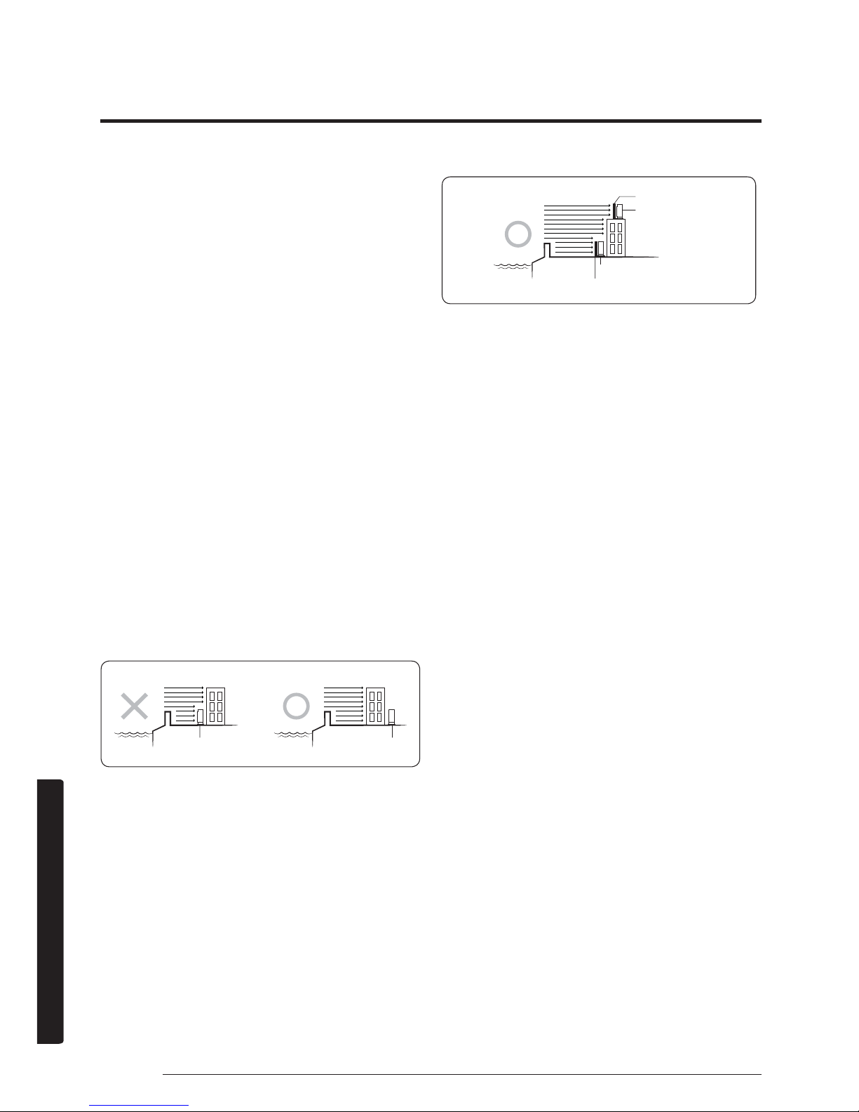
ŷ When installing the outdoor unit at the seaside, make
sure that it is not directly exposed to sea breeze. If
you cannot find an adequate place free from direct
sea breeze, construct a protection wall or a protective
fence.
– Install the outdoor unit in a place (such as near
buildings etc.) where it can be protected from sea
breeze. Failure to do so may cause a damage to the
outdoor unit.
ŷ If you cannot avoid installing the outdoor unit at the
seaside, construct a protection wall around to block the
sea breeze.
ŷ Construct a protection wall with a solid material such
as concrete to block the sea breeze. Make sure that
the height and the width of the wall are 1.5 times
larger than the size of the outdoor unit. Also, secure
a space larger than 23.6inch(600 mm) between the
protection wall and the outdoor unit for exhausted air
to ventilate.
ŷ Install the unit in a place where water can drain
smoothly.
ŷ If you have any difficulty finding installation location
as prescribed above, contact your manufacturer for
details.
ŷ Be sure to clean the sea water and the dust on the heat
exchanger of the outdoor unit and apply a corrosion
inhibitor on it. (At least once in a year.)
Power supply line, fuse, or circuit
breaker
ŷ Always make sure that the power supply is compliant
with current safety standards. Always install the air
conditioner in compliance with current local safety
standards.
ŷ Always verify that a suitable grounding connection is
available.
ŷ Verify that the voltage and frequency of the power
supply comply with the specifications and that the
installed power is sufficient to ensure the operation of
any other domestic appliance connected to the same
electric lines.
ŷ Always verify that the cut-off and protection switches
are suitably dimensioned.
ŷ Verify that the air conditioner is connected to the
power supply in accordance with the instructions
provided in the wiring diagram included in the manual.
ŷ Always verify that electric connections (cable entry,
section of leads, protections…) are compliant with
the electric specifications and with the instructions
provided in the wiring scheme. Always verify that all
connections comply with the standards applicable to
the installation of air conditioners.
ŷ Use Copper Supply Wires.
Sea breeze
Protection wall
Outdoor unit
Sea
Outdoor unit
Protection wall
Sea breeze
Outdoor unit
Sea
Sea breeze
Sea
Outdoor unit
Page 34
33English
Installation
Preparation
Step 1.1 Choosing the installation
location
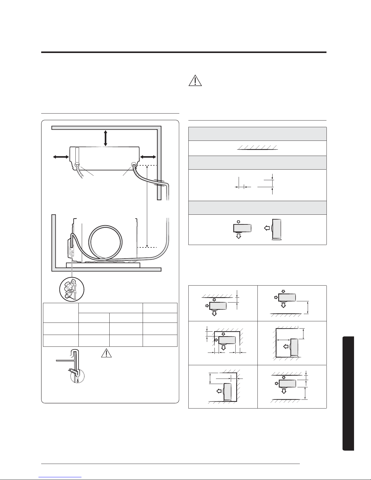
Overview of installation location requirements
CAUTION
CAUTION
ŷ Comply with the length and height limits described in
the figure above.
Minimum clearances for the outdoor unit
Wall
Minimum clearance in inch
11.8
23.6
Air flow direction
When installing 1 outdoor unit
(6 cases)
(Unit: inch)
11.8
59
11.8
5.9 23.6
59
78.74
19.6
11.8
11.859
Model
Pipe length Pipe height
Minimum Maximum Maximum
77
09/12
77
9.8ft(3m) 49.2ft(15m) 26.2ft(8m)
77
18/24
77
9.8ft(3m) 98.4ft(30m) 49.2ft(15m)
3.9inch(100 mm) or more
4.9inch
(125 mm)
or more
Drain hose hole
You can select the direction of
draining (left or right).
Maximum pipe height: 49.2ft(15m)
Maximum pipe length: 98.4ft(30 m)
Make at least one round to
reduce noise and vibration.
The actual units may look different from
the images depicted here.
Make a U-trap (A) on the pipe
(which is connected to the
indoor unit) at outer wall and
cut the bottom part of the
insulation (about 0.4inch(10
mm)) to prevent rainwater
from getting inside through
the insulation.
Outdoor
Unit
Outer wall
Indoor
Unit
Cut insulation to have
rainwater drained
Top view
Side view
4.9inch
(125 mm)
or more
Page 35
34 English
Installation
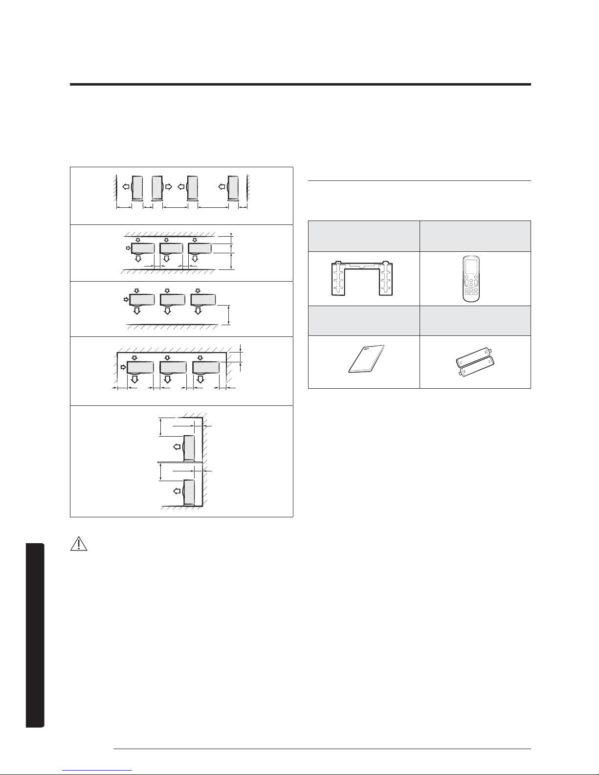
When installing more than 1 outdoor unit
(5 cases)
(Unit: inch)
59 23.6 11.8 7.811.8
11.859
23.6 23.6
59
11.8
11.8 23.6 23.6 23.6
19.6
11.8
19.6
11.8
CAUTION
ŷ If the outdoor unit is installed with any insufficient
clearance, it may generate sound and affect the whole
product.
ŷ Be sure to install the outdoor unit in a level place
where its vibration does not affect the whole product.
Step 1.2 Checking and preparing
accessories and tools
Accessories
Accessories in the indoor unit package
Installation plate (1) Remote control (1)
Manual users & Install
(1)
Remote control battery
(2)
Page 36
35English
Installation
Optional accessories
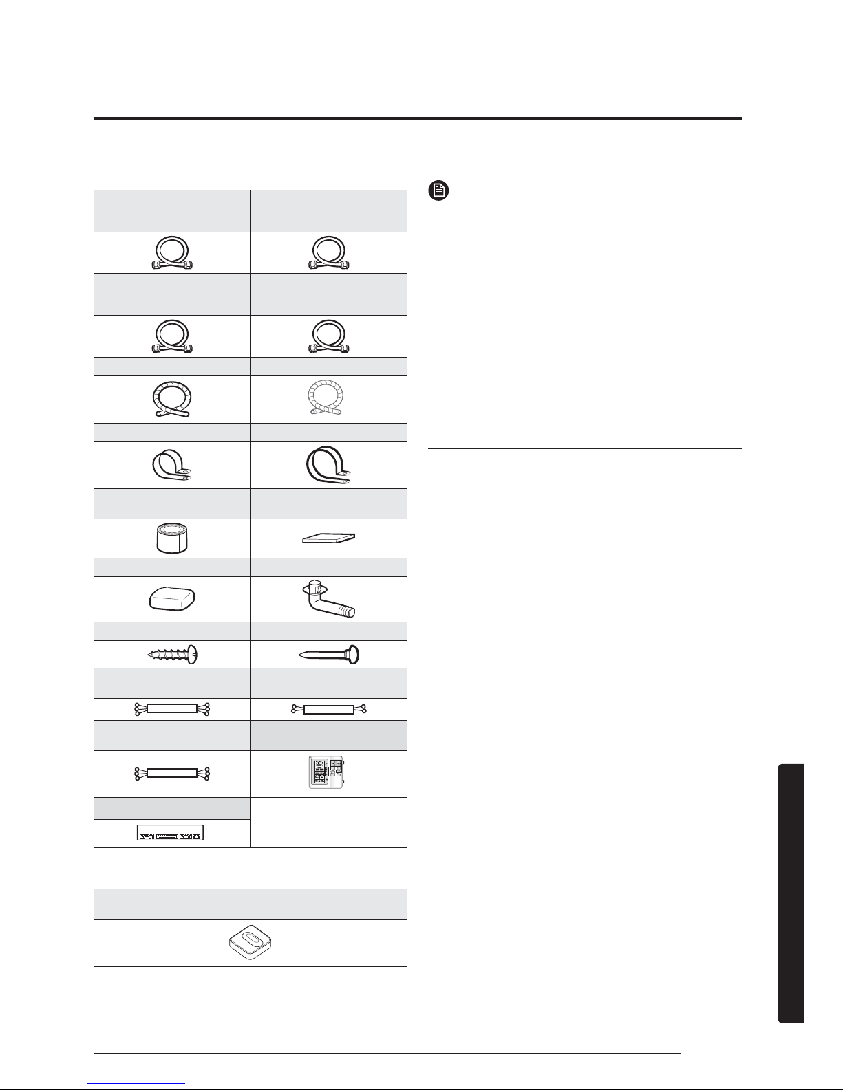
Insulated assembly pipe,
Ø1/4inch (Ø6.35mm) (1)
Insulated assembly pipe,
Ø3/8inch(9.52mm) (1)
7709/1277
Insulated assembly pipe,
Ø1/2inch(12.70mm) (1)
771877
Insulated assembly pipe,
Ø5/8inch(15.88mm) (1)
772477
Drain Hose, 2 m long (1) Foam Insulation(1)
Pipe clamp A (3) Pipe clamp B (3)
Vinyl tape (2)
PE T3 foam tube
insulation (1)
Putty 100 g (1) Drain plug (1)
M4 x 25 tapped screw (6) Cement nail (6)
3-wire power cable (1)
2-wire assembly cable
(1)
3-wire assembly cable
(1)
Wired remote controller
(1)
Sub COMM PBA
Accessories in the outdoor unit package
Rubber leg (4)
NOTE
ŷ A flare nut is attached to the end of each pipe of an
evaporator or a service port. Use flare nuts when
connecting the pipes.
ŷ Wire assembly cables are optional. If they are not
supplied, use standard cables.
ŷ The drain plug and the rubber legs are included only
when the air conditioner is supplied without assembly
pipes.
ŷ If these accessories are supplied, they are in the
accessory package or outdoor unit package.
ŷ Wired remote controller is optional. It has no Filter
Reset function in this model.
ŷ At cool mode, when wireless Remote controller temp
setting is from 61oF~64oF, wired Remote controller
FDQGLVSOD\WKHVHWWLQJWHPSFRUUHFWO\EXWFDQŰWVHW
TEMP below from 64oF to 61oF .
Tools
General tools
ŷ Vacuum pump
(Backward flowing
prevention)
ŷ Manifold gauge
ŷ Stud finder
ŷ Torque wrench
ŷ Pipe cutter
ŷ Reamer
ŷ Pipe bender
ŷ Spirit level
ŷ Screwdriver
ŷ Spanner
ŷ Drill
ŷ L-wrench
ŷ Measuring tape
Tools for test operation
ŷ Thermometer
ŷ Resistance meter
ŷ Electroscope
Step 1.3 Drilling a hole through the
wall
Before fixing the installation plate to a wall and then
fixing the indoor unit to the installation plate, a window
frame, or a gypsum board, you must determine the
position of a hole (with 2.56 inch(65 mm) inner diameter)
through which the pipe bundle (consisting of power and
communication cables, refrigerant pipes, and drain hose)
will pass and then drill that hole.
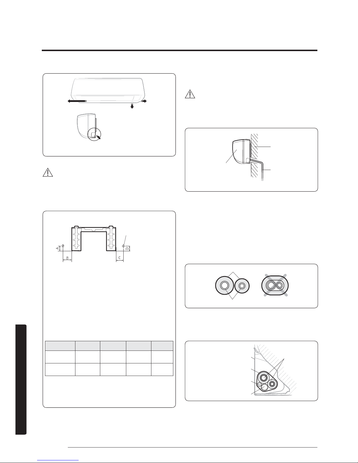
1. Determine the position of a
2.56 inch(65 mm)
mm hole in consideration of the possible
directions of the pipe bundle and the
minimum distances between the hole and
the installation plate.
Page 37
36 English
Installation
CAUTION
ŷ If changing the pipe direction from left to right, do not
drastically bent it but slowly turn it in the opposite
direction as shown. Otherwise, the pipe may be
damaged in the process.
1. Drill the hole.
CAUTION
ŷ Be sure to drill only one hole.
ŷ Make sure that the hole slants downwards so that the
drain hose slants downwards to drain water well.
Step 1.4 Taping the pipes, cables, and
drain hose
1. Wrap foam insulation on parts without
insulation on the ends of the refrigerant
pipes, as shown in the figure. This
wrapping minimises condensation problem.
2. Wind the refrigerant pipes, power cable,
communication cable and drain hose with
vinyl tape to make a pipe bundle.
<Possible directions of the pipe bundle>
Left Right
Rear right or left
Bottom righ
t
Wall
Drain hose
Indoor unit
<The hole slants downwards>
Insulation
Refrigerant pipes
Refrigerant pipes
(assembly pipe)
Installation plate
Vinyl tape
Power and communication cables
(assembly cable)
Drain hose
Pipe bundle hole
(Unit : inch (mm))
Model A B C D
7709/1277
1.2(
30) 3.8(96) 1.5(38) 1.2(30)
7718/2477
1.5(38) 5.0(126) 2.8(70) 1.5(38)
Pipe bundle hole: Ø 2.56 inch (Ø65 mm)
<Minimum distances between the hole
and the installation plate>
Pipe bundle hole
Page 38
37English
Installation
Step 2.1 Connecting the power and
communication cables (assembly
cable)
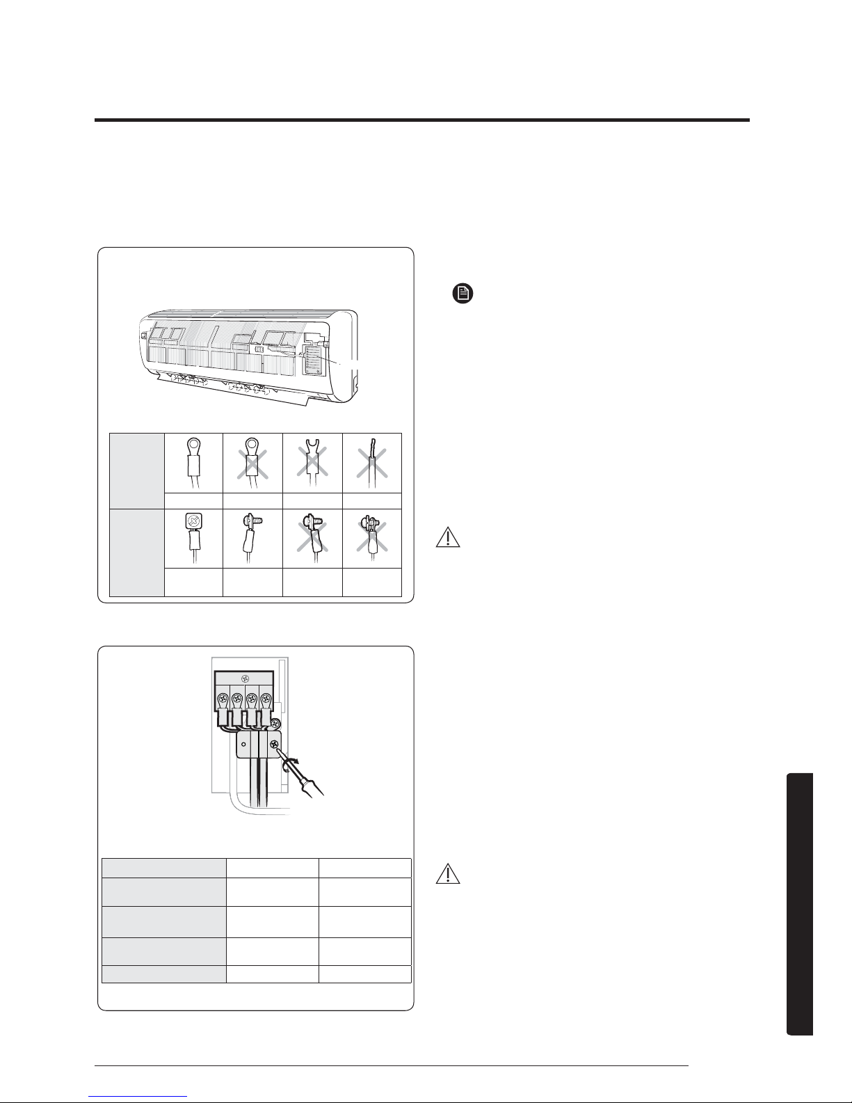
L1 L2 F1 F2
ŷ When performing electrical and earthing works,
be sure to comply with the 'technical standards of
electrical installations' and the 'wiring regulations' in
the local regulations.
ŷ Tighten the terminal block screw to 0.89
~
1.33lbtft [1.2
~
1ŷP~NJIŷFP@
ŷ NOTE
ŷ Each wire is labelled with the corresponding terminal
number.
ŷ Use shield cable (Category 5; less than 50pF/m) for
noisy environmental site.
ŷ Power supply cords of parts of appliances for outdoor
use shall not be lighter than polychloroprene sheathed
flexible cord. (Code designation IEC: 60245 IEC 66/
CENELEC: H07RN-F, IEC: 60245 IEC 57/CENELEC:
H05RN-F)
ŷ Power & Communication cable shall not exceed
98.42ft(30m).
CAUTION
ŷ For the terminal block wiring, use a wire with a
ring terminal socket only. Regular wires without a
ring terminal socket may become a hazard due to
overheating of the electrical contact during installation.
ŷ If you need to extend the pipe, be sure to extend
the cable too. The maximum length of each of the
cable and pipe used should not exceed 49.2ft(15m)
(7709/1277)/98.4ft(30m)(7718/2477).
ŷ Do not connect two or more different cables to extend
the length. This connection may cause fire.
ŷ Each circular terminal must match the size of its
corresponding screw in the terminal block.
ŷ After connecting the cables, make sure that terminal
numbers on the indoor and outdoor units match.
ŷ Ensure that power and communication cables are
separated, they must not be in the same cable.
WARNING
ŷ Connect the wires firmly so that wires cannot be pulled
out easily. (If they are loose, it could cause burn-out of
the wires.)
Model 7709/12/1877 772477
Power cable
(Outdoor unit)
3G X 1.5 mm²,
H07RN-F
3G X 2.5 mm²,
H07RN-F
Outdoor-to-indoor
power cable
3G X 1.0 mm²,
H07RN-F
3G X 1.0 mm²,
H07RN-F
Communication
cable
2 X 0.75 mm²,
H05RN-F
2 X 0.75 mm²,
H05RN-F
Type GL 20A 25A
Before
connecting
Correct Upside down Damaged Non-circular
After
connecting
Correct Correct
Upside down Non-fitted
(Front view) (Side view)
<Circular terminal>
Control box
Fasten the screws for the wire holders.
Indoor Unit Installation
Page 39
38 English
Installation
Step 2.2 Optional: Extending the
power cable
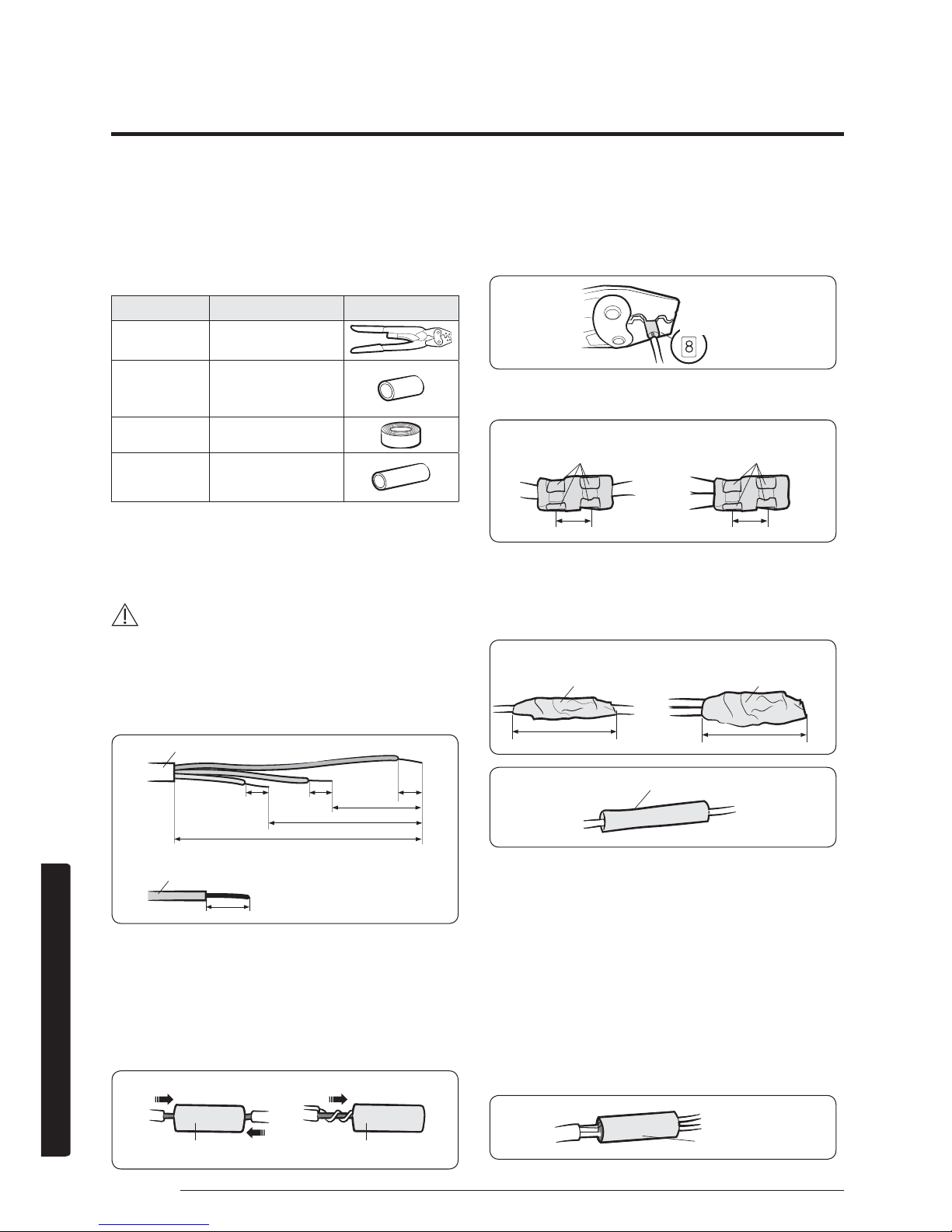
1. Prepare a compressor and the following
tools.
Tools Spec Shape
Crimping
pliers
MH-14
Connection
sleeve
0.79xØ0.28inch
((20xØ7.0mm)
(HxOD))
Insulation
tape
Width
0.71inch(18mm)
Contraction
tube
1.97x Ø0.31inch
(50xØ8.0mm)
(LxOD)
2. As shown in the figure, peel off the shields
from the rubber or wire of the power cable.
ŷ Peel off 0.79 inch ( 20 mm ) of the wire shields of
the tube installed already.
CAUTION
ŷ For information about the power cable
specifications for indoor and outdoor units, refer to
the installation manual.
ŷ After peeling off the tube wire, you must insert a
contraction tube.
0.79(20)
2.36(60)
4.72(120)
0.79(20)
0.79(20)
0.79(20)
7.09(180)
3. Insert both sides of core wire of the power
cable into the connection sleeve.
ŷ Method 1: Push the core wire into the sleeve from
both sides.
ŷ Method 2: Twist the wire cores together and push it
into the sleeve.
4. Using a compressor, compress the two
points and flip it over and compress another
two points in the same location.
ŷ The compression dimension should be 8.0.
ŷ After compressing it, pull both sides of the wire to
make sure it is firmly pressed.
5. Wrap it with the insulation tape twice or
more and position your contraction tube in
the middle of the insulation tape.
A total of three or more layers of insulation is required.
6. Apply heat to the contraction tube to
contract it.
7. After tube contraction work is completed,
wrap it with the insulation tape to finish.
ŷ Make sure that the connection parts are not
exposed to outside.
ŷ Be sure to use insulation tape and a contraction
tube made of approved reinforced insulating
materials that have the same level of withstand
voltage with the power cable. (Comply with the
local regulations on extensions.)
Power cable (provided by us)
Wire tube power cable
(Unit:inch(mm))
(Unit:inch(mm))
Method 1
Method 2
Connection sleeve
Connection sleeve
Compression
dimension
Compress it 4 times
Compress it 4 times
Method 1
Method 2
0.20inch(5 mm)
Insulation tape
Method 1 Method 2
Insulation tape
1.57inch(40 mm)
1.37inch(35 mm)
Contraction tube
Insulation tape
0.20inch(5 mm)
Page 40
39English
Installation
WARNING
ŷ In case of extending the electric wire, please DO NOT
use a round-shaped pressing socket.
– Incomplete wire
connections can cause
electric shock or a fire.
Step 2.3 Installing and connecting the
drain hose
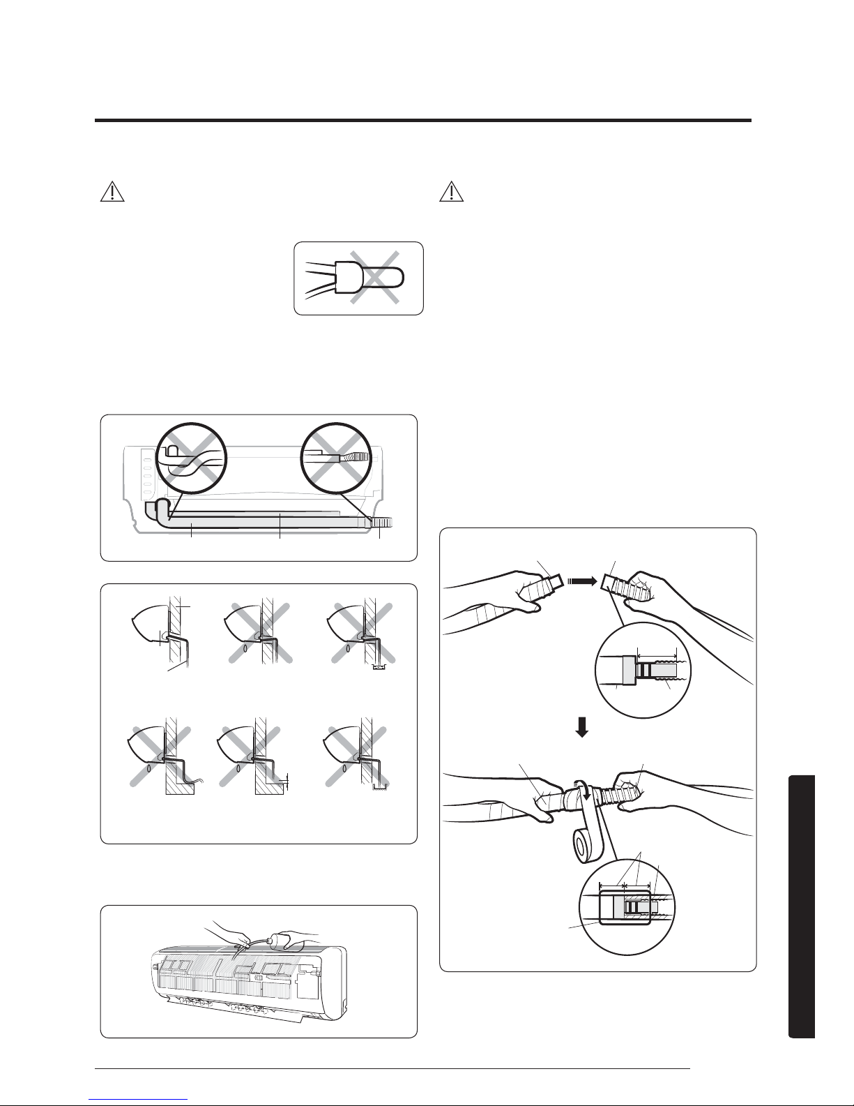
1. Install the drain hose.
2. Pour water into the drain pan. Check
whether the hose is well drained.
CAUTION
ŷ Make sure that the indoor unit is in upright position
when you pour water to check for leakage. Make sure
that the water does not overflow onto the electrical
part.
ŷ If the diameter of the connection hose is smaller than
the product's drain hose, water leakage may occur.
ŷ Inadequate installation may cause water leakage.
ŷ If the drain hose is routed inside the room, insulate the
hose so that dripping condensation does not damage
the furniture or floors.
ŷ Do not box in or cover the drain hose connection.
Drain hose connection must be easily accessible and
serviceable.
Step 2.4 Optional: Extending the drain
hose
(A) (B)
Drain hose Assembly pipe
Connection hose
Indoor unit
Drain hose
Wall
2inch(5cm)
less
Ditch
Slant downwards Slant upwards Dipped in water
Bent
Too small
clearance
Too small
clearance
Drain hose (A) Extension drain hose (B)
Drain hose
Extension drain hose
0.79 inch (20 mm)
or more
Foam insulation
Vinyl tape
1.57~1.77inch
(40
~
45mm
)
Page 41
40 English
Installation
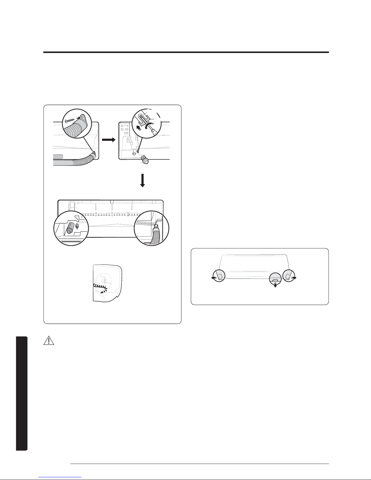
Step 2.5 Optional: Changing the
direction of the drain hose
CAUTION
ŷ Make sure that the indoor unit is in upright position
when you pour water to check for leakage. Make sure
that the water does not overflow onto the electrical
part.
Step 2.6 Installing and connecting
the assembly pipes to the refrigerant
pipes (assembly pipe)
Connect indoor and outdoor units with field-supplied
copper pipes by means of flare connections. Use insulated
seamless refrigeration grade pipe only, (Cu DHP type
according to ISO1337), degreased and deoxidized, suitable
for operating pressures of at least 4200 kPa and for burst
pressure of at least 20700 kPa. Under no circumstances
must sanitary type copper pipe be used.
There are 2 refrigerant pipes of different diameters:
ŷ The smaller one is for the liquid refrigerant
ŷ The larger one is for the gas refrigerant
A short liquid refrigerant pipe and a short gas refrigerant
pipe are already fitted to the air conditioner. The
connection procedure for the refrigerant pipes varies
according to the exit position of each pipe when facing
the wall:
1. Cut out the appropriate knock-out piece (A,
B, C) on the rear of the indoor unit unless
you connect the pipe directly from the rear.
2. Smooth the cut edges.
Drain pan outlet
Rubber cap
Pour water in the direction of arrow.
Direction of the drained water
<Front view>
<Side view>
Left(A)
Underside(C)
Right(B)
Page 42
41English
Installation
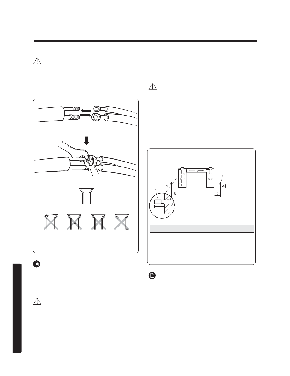
1. Remove the protection caps of the pipes and
connect the assembly pipe to each pipe. Tighten
the nuts first with your hands, and then with a
torque wrench, applying the following torque:
Outer diameter
Torque
1ŷP
Torque
fWŷOENJIŷFP
ø
1/4 inch(ø6.35mm)
14~18
10.1~13.0
(140~180)
ø
3/8 inch(ø9.52mm)
34~42
25.3~31.1(350~430)
ø
1/2 inch(
ø12.70 mm)
49~61
36.2~44.8(500~620)
ø
5/8 inch(ø15.88mm)
68~82
49.9~60.0(690~830)
NOTE
ŷ If you want to shorten or extend the pipes, see Step
2.9 Shortening or extending the refrigerant pipes
(assembly pipe) on page 41.
2. Cut off the remaining foam insulation.
3. If necessary, bend the pipe to fit along the
bottom of the indoor unit. Then pull it out
through the appropriate hole.
ŷ The pipe should not project from the rear of the indoor
unit.
ŷ The bending radius should be 3.94 inch (100 mm) or
more.
4. Pass the pipe through the hole in the wall.
5. Fix the indoor unit on the wall.Pass the cables,
pipes and hose through the knock-out hole
which would be connected to the outdoor unit .
6. Use 2 screws to fix the indoor unit as shown in
the picture 2.
7. Assemble the Guide into the position of A or B
as shown in the picture 3.
NOTE
ŷ The pipe will be insulated and fixed permanently into
position after finishing the installation and the gas leak test.
For further details. see Step 4.1 Performing the gas leak
tests on page54.
CAUTION
ŷ Tighten the flare nut with a torque wrench according to
specified method. If the flare nut is over-tightened, the flare
may break and cause refrigerant gas leakage.
ŷ Do not box in or cover the pipe connection. All refrigerant
pipe connection must be easily accessible and serviceable.
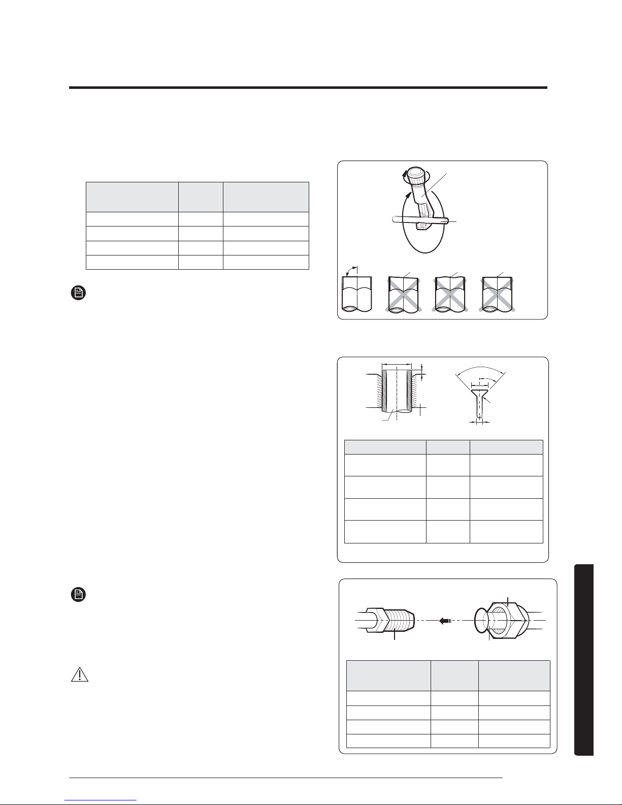
Step 2.7 Shortening or extending the
refrigerant pipes (assembly pipe)
90°
R 0.4 to 0.8
90°±2°
45°±2°
L
D
D
A
Outer diameter (D) Depth (A) Flare dimension (L)
ø
1/4 inch(ø6.35mm)
0.051inch
(1.3mm)
0.3425 - 0.3583 inch
(8.7 - 9.1 mm)
ø
3/8 inch(ø9.52mm)
0.071inch
(1.8mm)
0.5039 - 0.5197 inch
(12.8 - 13.2 mm)
ø
1/2 inch(
ø12.70 mm)
0.079inch
(2.0mm)
0.6378 - 0.6535 inch
(16.2 - 16.6 mm)
ø
5/8 inch(ø15.88mm)
0.087inch
(2.2mm)
0.7598 - 0.7756 inch
(19.3 - 19.7 mm)
Outer diameter
Torque
1ŷP
Torque
fWŷOENJIŷFP
ø
1/4 inch(ø6.35mm) 14~18
10.1~13.0
(140~180)
ø
3/8 inch(ø9.52mm)
34~42
25.3~31.1(350~430)
ø
1/2 inch(
ø12.70 mm)
49~61
36.2~44.8(500~620)
ø
5/8 inch(ø15.88mm) 68~82
49.9~60.0(690~830)
Pipe cutter
Pipe
Oblique Rough
Burr
Pipe
Flare
Indoor outlet
pipe
Connecting
pipe
Flare nut
Page 43
42 English
Installation
CAUTION
ŷ If you need a pipe longer than specified in piping codes
and standards, you must add refrigerant to the pipe.
Otherwise, the indoor unit may freeze.
ŷ While removing burrs, put the pipe face down to make
sure that the burrs do not get in to the pipe.
NOTE
ŷ Excessive torque may cause gas leakage. When
extending the pipe with welding or brazing, ensure that
nitrogen is used during the welding or brazing process.
The joint must be accessible and serviceable.
CAUTION
ŷ Tighten the flare nut at the specified torque. If the flare
nut is over-tightened, it may break to cause leakage of
refrigerant gas.
Step 2.8 Fixing the installation plate
You can install the indoor unit on a wall, window frame, or
gypsum board.
WARNING
ŷ Make sure that the wall, window frame, or gypsum
board can withstand the weight of the indoor unit. If
you install the indoor unit in a place where it is not
strong enough to withstand the unit's weight, the unit
could fall and cause injury.
When fixing the indoor unit on a wall
Fix the installation plate to the wall giving attention to the
weight of the indoor unit.
NOTE
ŷ If you mount the plate to a concrete wall using plastic
anchors, make sure that gaps between the wall and the
plate, created by projected anchor, is less than 0.79 inch
(20 mm).
When fixing the indoor unit on a window frame
1. Determine the positions of the wooden
uprights to be attached to the window
frame.
2. Attach the wooden uprights to the window
frame giving attention to the weight of the
indoor unit.
<Flare nut>
Liquid service port
<High pressure>
Gas service port
<Low pressure>
Correct
Inclined Cracked
Uneven
thickness
Damaged
surface
Plastic
anchor
Wall
0.79inch
(20 mm)
Pipe bundle hole
(Unit : inch (mm))
Model A B C D
7709/1277
1.2(
30) 3.8(96) 1.5(38) 1.2(30)
7718/2477
1.5(38) 5.0(126) 2.8(70) 1.5(38)
Pipe bundle hole: Ø 2.56 inch (Ø65 mm)
Page 44
43English
Installation
3. Attach the installation plate to the wooden
upright using tapping screws.
When fixing the indoor unit on a gypsum board
1. Use stud finder to find out locations of the
studs.
2. Fix the plate hanger on two studs.
CAUTION
ŷ If you fix the indoor unit on a gypsum board, use
only specified anchor bolts on reference positions.
Otherwise, the gypsum surrounding the joints may
crumble over time and cause the screws to be
loosened and stripped. This may lead to physical injury
or equipment damage.
ŷ Search for other spots if there are less than two studs,
or the distance between the studs are different from
the plate hanger.
ŷ Fix the installation plate without inclining to one side.
Page 45
44 English
Installation
Step 3.1 Fixing the outdoor unit in
place
X
Y
1. Place the outdoor unit as directed on the
top of the unit to let the discharged air out
properly.
2. Fix the outdoor unit in level to an
appropriate support using anchor bolts.
NOTE
ŷ Secure the rubber legs to help prevent the generation
of noise and vibration.
ŷ If the outdoor unit is exposed to strong winds, install
shield plates around the outdoor unit so that the fan
can operate correctly.
Optional: Fixing the outdoor unit to a wall with
a rack
NOTE
ŷ Make sure that the wall can support the weights of the
rack and the outdoor unit.
ŷ Install the rack close to the column as much as
possible.
Step 3.2 Connecting the power
and communication cables and the
refrigerant pipes
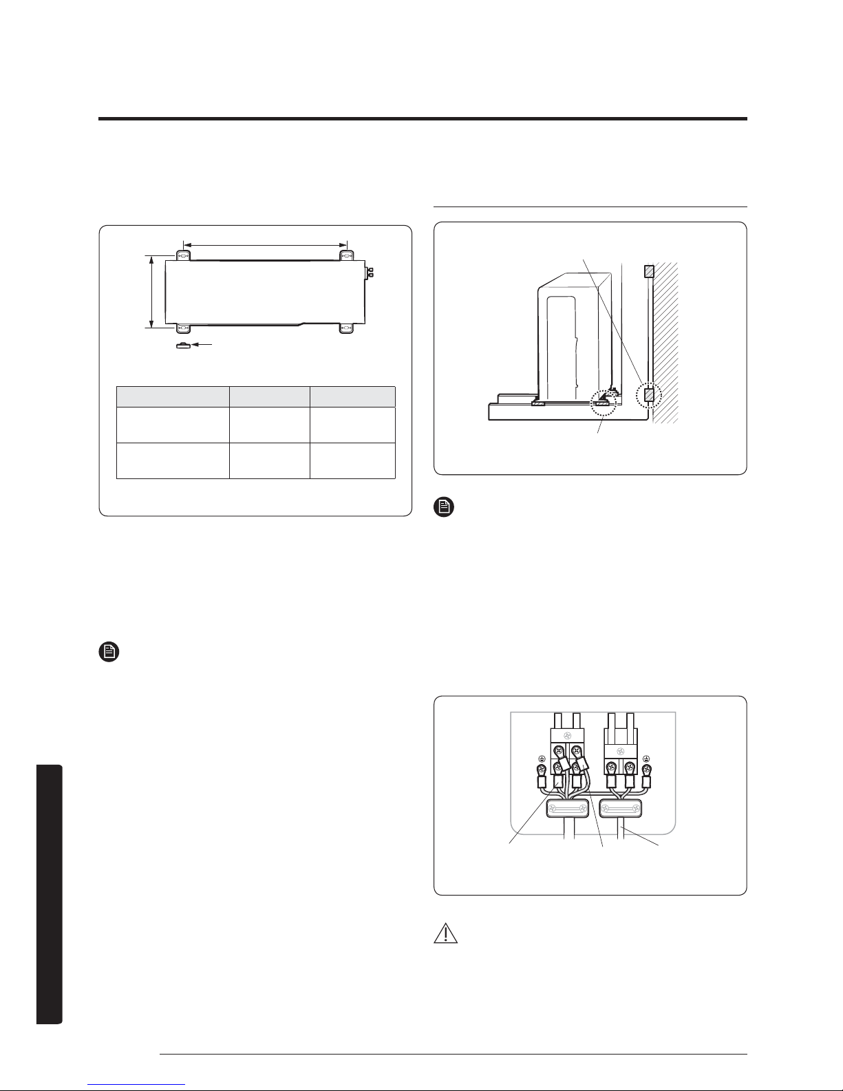
F1 F2
L1 L2
CAUTION
ŷ Be sure to fix the power cables and communication
cable with a cable clamp.
(Unit : ft/mm)
Model X Y
7709/1277
2.01ft
(612mm)
1.04ft
(317mm)
7718/2477
2.16ft
(660mm)
1.12ft
(340mm)
Rubber leg
Soft rubber designed to cut off vibration from rack
to wall (not supplied with product)
Soft rubber designed to cut off residual vibration from
outdoor unit to rack (not supplied with product)
Outdoor-to-indoor power
cable (three wires)
Communication cable
(two wires)
Power cable
(three wires)
Outdoor Unit Installation
Page 46
45English
Installation
Step 3.3 Evacuating the air
The outdoor unit is loaded with sufficient R-410A
refrigerant. Do not vent R-410A into atmosphere: it is a
fluorinated greenhouse gas, covered by Kyoto Protocol,
with a Global Warming Potential (GWP) = 2088. You
should evacuate the air in the indoor unit and in the
pipe. If air remains in the refrigerant pipes, it affects the
compressor. It may cause reduction of cooling capacity and
malfunction. Use a vacuum pump.
CAUTION
ŷ When installing, make sure there is no leakage. When
recovering the refrigerant, ground the compressor first
before removing the connection pipe. If the refrigerant
pipe is not properly connected and the compressor
works with the stop valve open, the pipe inhales the air
and it makes the pressure inside of the refrigerant cycle
abnormally high. It may cause explosion and injury.
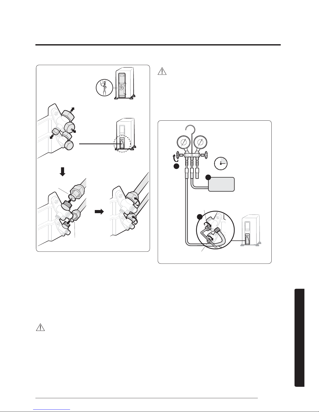
1. Leave the system in the standby mode.
WARNING
ŷ Do not turn on the system! This is necessary for
better vacuum operation (full OPEN position of
Electronic Expansion Valve).
2. Connect the charging hose of the low
pressure side of manifold gauge to a gas
service port as seen in the picture.
Z
[
\
3. Open the valve of the low pressure side of
manifold gauge anticlockwise.
4. Evacuate the air in the connected pipes
using the vacuum pump for about 15
minutes.
ŷ Make sure that pressure gauge shows -0.1 MPa
(-76 cmHg, 5 torr) after about 10 minutes. This
procedure is very important to avoid a gas leak.
ŷ Close the valve of the low pressure side of
manifold gauge clockwise.
ŷ Turn off the vacuum pump.
ŷ Check for 2 minutes if there is any pressure
change.
ŷ Remove the hose of the low pressure side of
manifold gauge.
5. Set a valve cork of liquid and gas service
port to the open position.
Control box
Remove the screw for the
control box cover
For connecting the
refrigerant pipes
Remove the gas and liquid
service port caps
Gas service port
<Low pressure>
Liquid service port
<High pressure>
Connect the gas and liquid
refrigerant pipes
(Backward flowing prevention)
Liquid service port <Low pressure>
Vacuum
Pump
Valve 15 minutes
Liquid service port <High pressure>
Page 47
46 English
Installation
Step 3.4 Adding refrigerant
If you use a pipe longer than the length specified in
the piping codes and standards, you must add 15g of
refrigerant R-410A for each extra metre. If you use a pipe
shorter than the length specified in the piping codes and
standards, the evacuating time is normal. Refer to the
Service Manual for further details.
CAUTION
ŷ The remaining air in the Refrigeration cycle, which
contains moisture, may cause malfunction of the
compressor.
ŷ Always contact the service centre or a professional
installation agency for product installation.
R-410A is a mixed type of refrigerant. It is necessary for
recharging under conditions of liquid. When recharging
refrigerant from the refrigerant cylinder to the equipment,
take the following instructions:
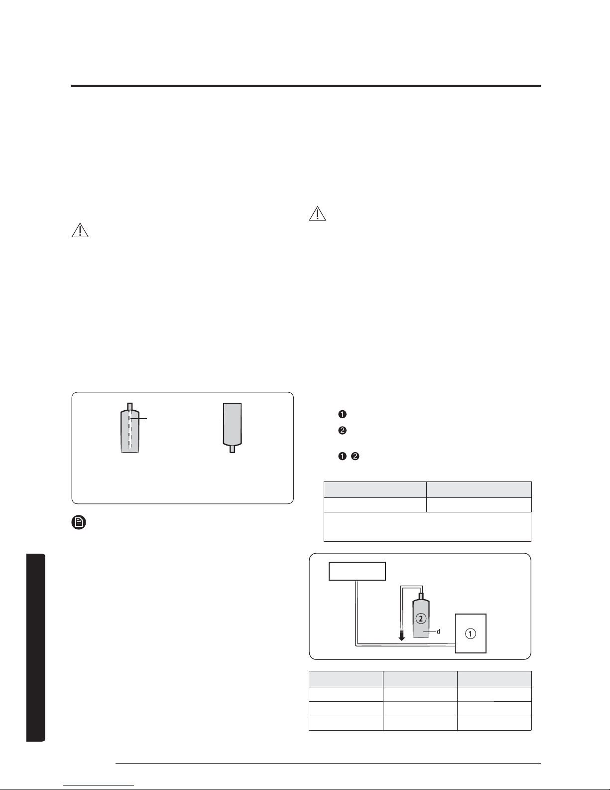
Before recharging, check whether the cylinder has
a siphon or not. There are two ways to recharge the
refrigerant:
NOTE
ŷ If R-410A refrigerant is charged with gas, the
composition of the charged refrigerant changes and
the characteristics of the equipment vary.
ŷ During the measuring operation of refrigerant quantity
added, use electronic scales. If cylinder doesn't have
siphon, upset it.
Step 3.5 Important information
regulation regarding the refrigerant
used
This product contains fluorinated greenhouse gases. Do
not vent gases into the atmosphere.
CAUTION
ŷ Inform user if system contains 5 tCO2e or more of
fluorinated greenhouse gases. In this case, it has to be
checked for leakage at least once every 12 months,
according to regulation n°517/2014. This activity has
to be covered by qualified personnel only. In case
situation above (5 tCO
2
e or more of R-410A), installer
(or recognized person which has responsibility for
final check) has to provide a maintenance book, with
all the information recorded according to REGULATION
(EU) No 517/2014 OF THE EUROPEAN PARLIAMENT
AND OF THE COUNCIL of 16 April 2014 on fluorinated
greenhouse gases.
1. Please fill in the following with indelible
ink on the refrigerant charge label supplied
with this product and on this manual.
ŷ
the factory refrigerant charge of the product,
ŷ
the additional refrigerant amount charged in
the field and
ŷ
+ the total refrigerant charge. on the
refrigerant charge label supplied with the product.
Refrigerant type GWP value
R-410A 2088
tGWP=Global Warming Potential
tCalculating tCO
2
e : kg x GWP / 1000
Unit Kg tCO2e
①, a
②, b
①+②, c
Indoor unit
Outdoor unit
Charge the refrigerant standing
the cylinder upright
.
<Cylinder with siphon>
Charge the refrigerant turning
the cylinder upside down.
Siphon
<Cylinder without siphon>
Page 48
47English
Installation
NOTE
a Factory refrigerant charge of the product: see unit
name plate
b Additional refrigerant amount charged in the field
(Refer to the above information for the quantity of
refrigerant replenishment.)
C Total refrigerant charge
d Refrigerant cylinder and manifold for charging
CAUTION
ŷ The filled-out label must be adhered in the proximity
of the product charging port (e.g. onto the inside of the
stop valve cover).
Page 49
48 English
Installation
Step 4.1 Performing the gas leak tests
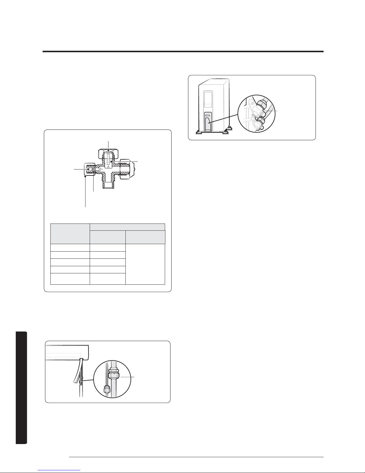
1. Before inspecting the leakage, use a torque
wrench to close the cap for the stop valve.
(Comply with a tightening torque for each size
of the diameter, and tighten the cap firmly to
prevent any leakage.)
2. Insert inert gas into the pipes connected to
indoor and outdoor units.
3. Test leakage on the connection parts of the
indoor and outdoor units with soap lather or
liquid.
Outer diameter
inch(mm)
Tightening torque
Body cap
fWŷOE1ŷP
Charging port cap
fWŷOE1ŷP
ø1/4inch(6.35mm)
14.8
~
18.4 (20~25)
7.4
~
8.9(10~12)
ø3/8inch(9.52mm)
14.8
~
18.4 (20~25)
ø1/2inch(12.70mm)
18.4
~
22.1(25~30
)
ø5/8inch(15.88mm)
22.1
~
25.8 (30~35)
Over
ø3/4inch(19.05mm)
25.8
~
29.5(35~40)
1ŷP NJIŷFP
Tightening torque for body cap
(Refer to the table)
Charging core
Spindle
R-22: Thread of the screw - 7/16-2OUNF
R-410A: Thread of the screw -1/2-2OUNF
Tightening torque for charging port cap
(Refer to the table)
Test parts for the
indoor unit
Test parts for the
indoor unit
Installation Inspection
Page 50
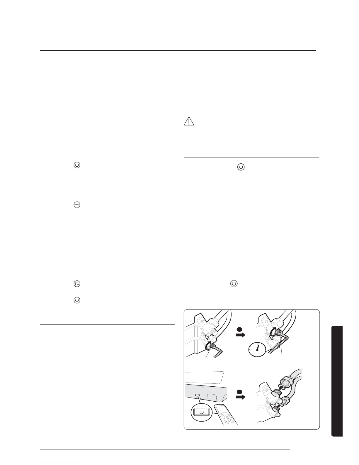
49English
Installation
Step 4.2 Performing final check and trial
operation
1. Check the following:
ŷ Strength of the installation site
ŷ Tightness of pipe connection to detect gas leak
ŷ Electric wiring connection
ŷ Heat-resistant insulation of the pipe
ŷ Drainage
ŷ Grounding conductor connection
ŷ Correct operation (Take the following steps.)
2. Press the (Power) button on the remote
control to check the following:
ŷ The indicator on the indoor unit lights up.
ŷ The airflow blade opens and the fan gears up for
operation.
3. Press the (Mode) button to select Cool or
Heat mode. Then take the following sub-steps:
ŷ In Cool mode, use the Temperature button to set the set
temperature to 61
°F(
16 °C).
ŷ In Heat mode, use the Temperature button to set the set
temperature to 86
°F(
30 °C).
ŷ Check whether, approximately 3 to 5 minutes later, the
outdoor unit starts, and a cool or warm air blows out.
ŷ After 12 minutes of stationary condition, check the
indoor unit air treatment.
4. Press the (Air swing) button to check
whether the airflow blades work properly.
5. Press the
(Power) button to stop the trial
operation.
Pumping down refrigerant
Pump-down is an operation intended to collect all the system
refrigerant in the outdoor unit. This operation must be carried
out before disconnecting the refrigerant tubing in order to avoid
refrigerant loss to the atmosphere.
1. Shut off the liquid valve with the Allen wrench.
2. Turn on the air conditioner in cooling with fan
operating at high velocity. (Compressor will
immediately start, provided 3 minutes have
elapsed since the last stop.)
3. After 2 minutes of operation, shut the suction
valve with the same wrench.
4. Turn off the air conditioner and switch
mains supply off.
5. Disconnect tubing. After disconnection,
protect valves and tubing ends from dust.
CAUTION
ŷ Compressor damage may occur if the compressor is
run at a negative suction pressure.
Pumping down for removing the product
1. Hold down the (Power) button on the
indoor unit for 5 seconds. Beep sounds
immediately to indicate that the product is
ready for pump down procedure.
2. Let the compressor run for more than 5
minutes.
3. Release the valve caps on High and Low
pressure side.
4. Use L-wrench to close the valve on the
high pressure side.
5. After approximately 1 minute, close the
valve on the low pressure side.
6. Stop operation of the air conditioner by
pressing the
(Power) button on the
indoor unit or remote control.
7. Disconnect the pipes.
X
Y
Liquid service port
<High pressure>
Gas service port
<Low pressure>
Off
1 minute
Page 51
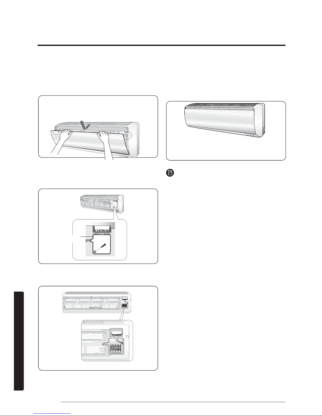
50 English
Installation
Sub PCB installation(optional)
(Wried remote controller, central remote controller etc.)
1. Turn the power off and take off the front
panel of the indoor unit.
2. Take off the Cover PCB.
3. Attach the Sub PCB to the right side of the
Panel-frame.
4. Find the PCB wire, and connect the wire to
the Sub PCB as seen in the picture.
5. Connect the wire(remote controller, central
remote controller etc) to the Sub PCB.
6. Assemble the Cover PCB and the front
panel.
NOTE
ŷ The Sub PCB is attached to be controlled by the wired
remote controller and central controller.
Case Sub PCB
Page 52
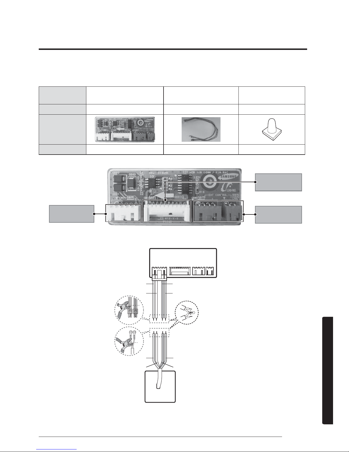
51English
Installation
Components parts
Description
RAC SUB PBA - Wired Remote Controller Wire Connection
Product name
RAC-SUB PBA
Haness Wire
(for Wired Remote controller)
Wire Joint
Quantity
1EA 1EA 4EA
Shape
Code
DB93-11412A DB93-11405A DB96-90020A
Wired Remocon
(1,2 : 12V / 4,5 : COM2)
RAC MAIN -SUB
Connection
External controller
connection (MIM-B14)
ORG
Wired Remote
Controller
RAC SUB PCB
Communication CablePOWER Cable
12V COM2
ORG
RED
RED
YEL
YEL
BLU
BLU
Wired remote controller installation (optional)
 Loading...