

Samsung AR**HSFS Series, AR**HSSD Series, AR**HSFN Series User & Installation Manual
A3050 EU_IM_DB68-04212A_HP_EN.indd 1 2013-10-23 16:31:10

Contents
Installation
Safety precautions . . . .. .. . .. . .. .. . .. . . . .. . .. . . . .. . .. . . . .. . .. . . . .. . .. .. . .. . .. .. . .. . . . .. . .. . . . .. . .. . . . .. . .. . . . .. . .. .. . .. . . . .. .3
Choosing the installation location .. . .. . . . .. . .. . . . .. . .. . . . .. . .. . . . .. . .. .. . .. . . . .. . .. . . . .. . .. . . . .. . .. . . . .. . .. . . . .. . .. .. . .. . . . .4
Accessories . . .. .. . .. . .. .. . .. . . . .. . .. . . . .. . .. . . . .. . .. . . . .. . .. .. . .. . .. .. . .. . . . .. . .. . . . .. . .. . . . .. . .. . . . .. . .. .. . .. . .. .. . .. . . . .. .7
Fixing the installation plate. . .. . . . .. . .. . . . .. . .. . . . .. . .. .. . .. . .. .. . .. . . . .. . .. . . . .. . .. . . . .. . .. . . . .. . .. .. . .. . .. .. . .. . . . .. . .. . . . .9
Disassembling/Assembling the Cover panel for indoor unit installation . .. . .. .. . .. . .. .. . .. . . . .. . .. . . . .. . .. . . . .. . .. . . . .. . .. . 10
Connecting the assembly cable . . . . .. . .. . . . .. . .. . . . .. . .. . . . .. . .. . . . .. . .. .. . .. . . . .. . .. . . . .. . .. . . . .. . .. . . . .. . .. . . . .. . .. .. . .. 12
Installing and connecting the assembly pipe of the indoor unit . . . . .. . .. . . . .. . .. . . . .. . .. .. . .. . .. .. . .. . . . .. . .. . . . .. . .. . . . .. . 14
Evacuating the indoor unit . .. . . . .. . .. . . . .. . .. . . . .. . .. . . . .. . .. . . . .. . .. .. . .. . . . .. . .. . . . .. . .. . . . .. . .. . . . .. . .. .. . .. . .. .. . .. . . . 15
Cutting or extending the pipe. .. . . . .. . .. . . . .. . .. . . . .. . .. . . . .. . .. . . . .. . .. .. . .. . . . .. . .. . . . .. . .. . . . .. . .. . . . .. . .. . . . .. . .. .. . .. 15
Installing and connecting the drain hose of the indoor unit . . . .. . .. . . . .. . .. . . . .. . .. .. . .. . .. .. . .. . . . .. . .. . . . .. . .. . . . .. . .. . . . 17
Changing direction of the drain hose. .. . .. . . . .. . .. .. . .. . .. .. . .. . . . .. . .. . . . .. . .. . . . .. . .. . . . .. . .. .. . .. . .. .. . .. . . . .. . .. . . . .. . 18
Installing and connecting the drain hose of the outdoor unit . . .. .. . .. . . . .. . .. . . . .. . .. . . . .. . .. . . . .. . .. .. . .. . .. .. . .. . . . .. . .. 19
Evacuating the connected pipes. .. . .. .. . .. . . . .. . .. . . . .. . .. . . . .. . .. . . . .. . .. .. . .. . . . .. . .. . . . .. . .. . . . .. . .. . . . .. . .. . . . .. . .. .. . 19
Performing the gas leak tests. . . . .. . .. .. . .. . . . .. . .. . . . .. . .. . . . .. . .. . . . .. . .. . . . .. . .. .. . .. . . . .. . .. . . . .. . .. . . . .. . .. . . . .. . .. . . . 22
Fixing the indoor unit in place. .. . . . .. . .. . . . .. . .. . . . .. . .. .. . .. . . . .. . .. . . . .. . .. . . . .. . .. . . . .. . .. . . . .. . .. .. . .. . . . .. . .. . . . .. . .. 23
Fixing the outdoor unit in place . .. . .. . . . .. . .. . . . .. . .. .. . .. . . . .. . .. . . . .. . .. . . . .. . .. . . . .. . .. . . . .. . .. .. . .. . . . .. . .. . . . .. . .. . . . 23
Smart Install mode. .. . . . .. . .. . . . .. . .. . . . .. . .. .. . .. . . . .. . .. . . . .. . .. . . . .. . .. . . . .. . .. .. . .. . .. .. . .. . . . .. . .. . . . .. . .. . . . .. . .. . . . 24
Final check and trial operation.. . .. . . . .. . .. . . . .. . .. .. . .. . .. .. . .. . . . .. . .. . . . .. . .. . . . .. . .. . . . .. . .. .. . .. . . . .. . .. . . . .. . .. . . . .. . 26
Pump down procedure (when removing the product) . . . . . . . . . . . . . . . . . . . . . . . . . . . . . . . . . . . . . . . . . . . . . . . . . . . . . . . . . . . . . . . . . . . . . 26
How to connect your extended power cables. .. . .. . . . .. . .. . . . .. . .. . . . .. . .. .. . .. . . . .. . .. . . . .. . .. . . . .. . .. . . . .. . .. . . . .. . .. .. . 27
Sub PCB installation(optional). . . . .. . .. . . . .. . .. .. . .. . .. .. . .. . . . .. . .. . . . .. . .. . . . .. . .. . . . .. . .. .. . .. . . . .. . .. . . . .. . .. . . . .. . .. . . 28
English-2
A3050 EU_IM_DB68-04212A_HP_EN.indd 2 2013-10-23 16:31:10

Carefully follow the precautions listed below because they are essential to guarantee the safety of the equipment.
• Always disconnect the air conditioner from the power supply before servicing it or accessing its internal components.
• Verify that installation and testing operations are performed by qualified personnel.
• Verify that the air conditioner is not installed in an easily accessible area.
General information
Carefully read the content of this manual before installing the air conditioner and store the manual in a safe place in order
to be able to use it as reference after installation.
For maximum safety, installers should always carefully read the following warnings.
Store the operation and installation manual in a safe location and remember to hand it over to the new owner if the air
conditioner is sold or transferred.
This manual explains how to install an indoor unit with a split system with two SAMSUNG units.
The use of other types of units with dierent control systems may damage the units and invalidate the warranty.
The manufacturer shall not be responsible for damages arising from the use of non compliant units.
This product has been determined to be in compliance with the Low Voltage Directive (2006/95/EC), and the
Electromagnetic Compatibility Directive (2004/108/EC) of the European Union.
The manufacturer shall not be responsible for damage originating from unauthorized changes or the improper connection
of electric and requirements set forth in the “Operating limits” table, included in the manual, shall immediately invalidate
the warranty.
The air conditioner should be used only for the applications for which it has been designed: the indoor unit is not suitable
to be installed in areas used for laundry.
Do not use the units if damaged. If problems occur, switch the unit o and disconnect it from the power supply.
In order to help prevent electric shocks, res or injuries, always stop the unit, disable the protection switch and contact
SAMSUNG’s technical support if the unit produces smoke, if the power cable is hot or damaged or if the unit is very noisy.
Always remember to inspect the unit, electric connections, refrigerant tubes and protections regularly. These operations
should be performed by qualied personnel only.
The unit contains moving parts, which should always be kept out of the reach of children.
Do not attempt to repair, move, alter or reinstall the unit. If performed by unauthorized personnel, these operations may
cause electric shocks or res.
Do not place containers with liquids or other objects on the unit.
All the materials used for the manufacture and packaging of the air conditioner are recyclable.
The packing material and exhaust batteries of the remote controller(optional) must be disposed of in accordance with
current laws.
The air conditioner contains a refrigerant that has to be disposed of as special waste. At the end of its life cycle, the air
conditioner must be disposed of in authorized centers or returned to the retailer so that it can be disposed of correctly and
safely.
Installing the unit
IMPORTANT: When installing the unit, always remember to connect rst the refrigerant tubes, then the electrical lines.
Always disassemble the electric lines before the refrigerant tubes.
Upon receipt, inspect the product to verify that it has not been damaged during transport.
If the product appears damaged, DO NOT INSTALL it and immediately report the damage to the carrier or retailer (if the
installer or the authorized technician has collected the material from the retailer.)
Safety precautions
Installation
English-3
A3050 EU_IM_DB68-04212A_HP_EN.indd 3 2013-10-23 16:31:10

After completing the installation, always carry out a functional test and provide the instructions on how to operate the air
conditioner to the user.
Do not use the air conditioner in environments with hazardous substances or close to equipment that release free ames to
avoid the occurrence of res, explosions or injuries.
To help prevent injury when accidentally touching the indoor unit fan, install the indoor unit at least 2.5m above the oor.
The air conditioner should be used only for the applications for which it has been designed : the indoor unit is not suitable
to be installed in areas used for laundry.
Our units must be installed in compliance with the spaces indicated in the installation manual to ensure either accessibility
from both sides or ability to perform routine maintenance and repairs. The units’ components must be accessible and that
can be disassembled in conditions of complete safety either for people or things.
For this reason, where it is not observed as indicated into the Installation Manual, the cost necessary to reach and repair the
unit (in safety, as required by current regulations in force) with slings, trucks, scaolding or any other means of elevation
won’t be considered in-warranty and charged to end user.
Power supply line, fuse or circuit breaker
Always make sure that the power supply is compliant with current safety standards. Always install the air conditioner in
compliance with current local safety standards.
Always verify that a suitable grounding connection is available.
Verify that the voltage and frequency of the power supply comply with the specications and that the installed power is
sucient to ensure the operation of any other domestic appliance connected to the same electric lines.
Always verify that the cut-o and protection switches are suitably dimensioned.
Verify that the air conditioner is connected to the power supply in accordance with the instructions provided in the wiring
diagram included in the manual.
Always verify that electric connections (cable entry, section of leads, protections…) are compliant with the electric
specications and with the instructions provided in the wiring scheme.
Always verify that all connections comply with the standards applicable to the installation of air conditioners.
Indoor unit
For Wi-Fi Air-conditioner installation, select indoor unit location near to wireless router.
In case Wi-Fi signal strength weakened , Smart APP may be disconnected depending on the Wi-Fi signal strength.
Where airow is not blocked.
Where cool air can be distributed throughout the room.
Install the refrigerant piping length and the height dierence of both indoor and outdoor units as indicated in the
installation diagram.
Wall that prevents vibration and is strong enough to hold the product weight.
Out of the direct sunlight .
1m or more away from the TV or radio (to prevent the screen from being distorted or noise from being generated).
As far away as possible from the uorescent and incandescent lights (so that the remote controller can be operated well).
A place where the air lter can be replaced easily.
Don't install directly above electronics equipment as leaking water may cause damage if not serviced. (eg. Computers, TV, etc).
Choosing the installation location
Safety precautions
English-4
A3050 EU_IM_DB68-04212A_HP_EN.indd 4 2013-10-23 16:31:10

Outdoor Unit
Where it is not exposed to strong wind
Well ventilated and dustless places
Where possible keep out of sunlight and rain
Where neighbors are not annoyed by operation sound or hot air
Solid wall or support that prevents vibration and is strong enough to hold the product weight
Where there is no risk of ammable gas leakage
When installing the unit at a high place be sure to x the unit legs
3 m or more away from the TV or radio (to prevent the screen from being distorted or noise from being generated)
Install the unit horizontally
Place where drained water does not become any problem.
Place with no plants (especially climbing plants) and where small animal can not access.
Outdoor unit should not be place higher than 2.4 m or directly under eaves for accessibility for service and OH&S reasons.
• Avoid the following places to prevent malfunction of the unit
- Where there is machine oil - Salty environment such as seaside areas
- Where sulde gas exists - Other special atmosphere areas
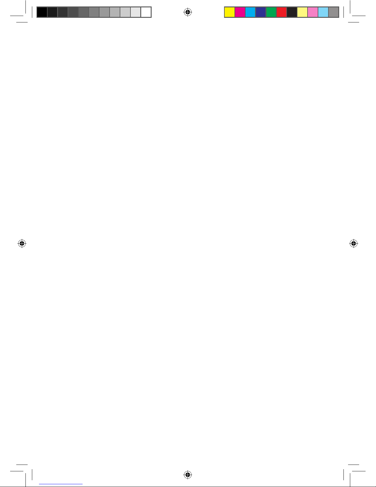
125 mm or
more
300 mm or more
125 mm
or more
600 mm
minimum
300 mm
minimum
300 mm
minimum
600 mm
minimum
'L' meters maximum total pipe
length
Wrap the refrigerant pipes and the drain hose
with the absorbent pad and vinyl tape. Refer to
page 23 for further details.
You can select the direction of
draining (left or right).
'H' meters maximum total
pipe height
The appearance of the unit may be dierent from the diagram depending on the model.
Make at least one round: It will help reduce noise and vibration.
'L' m as maximum pipe length
and 3 m as minimum pipe length.
(It will reduce noise and vibration)
Model L H
09/12
15 8
18/24
30 15
If using a multi system, install as described in the installation manual supplied with the outdoor unit.
English-5
A3050 EU_IM_DB68-04212A_HP_EN.indd 5 2013-10-23 16:31:10

Space Requirements for Outdoor Unit
When installing 1 outdoor unit
300 or more
When the air outlet is opposite the
wall
1500 or more
When the air outlet is towards the
wall
300 or more
150 or more 600 or more
When 3 sides of the outdoor unit are
blocked by the wall
1500 or more
2000 or more
The upper part of the outdoor unit
and the air outlet is towards the wall
500 or more
300 or more
The upper part of the outdoor unit
and the air outlet is opposite the
wall
When the walls are blocking front
and the rear side of the outdoor unit
300 or
more
1500 or
more
Top view Side view
Air outlet Air intake
Air intake
Air outlet
Figure Description
, Air flow direction.
(Unit : mm)
When installing more than 1 outdoor unit
(Unit : mm)
1500 or more
When the air outlet is towards the wall When 3 sides of the outdoor unit are blocked by the wall
300 or more
300 or more 600 or more 600 or more 600 or more
Choosing the installation location
If using a multi system, install as described in the installation manual supplied with the outdoor unit.
English-6
A3050 EU_IM_DB68-04212A_HP_EN.indd 6 2013-10-23 16:31:10
When the upper part of the outdoor unit and
the air outlet is opposite the wall
When the walls are blocking front and the rear side of the outdoor
units
When front and rear side of the outdoor unit is towards the wall
500 or more
300 or more
500 or more
300 or more
300 or
more
1500 or
more
600 or more 600 or more
1500 or
more
600 or
more
3000 or
more
200 or
more
3000 or
more
• If installation is done in inappropriate space, unit may generate sound and cause bad eect on the product.
• Installation must be done in level and in a place where vibration will not cause any eect.
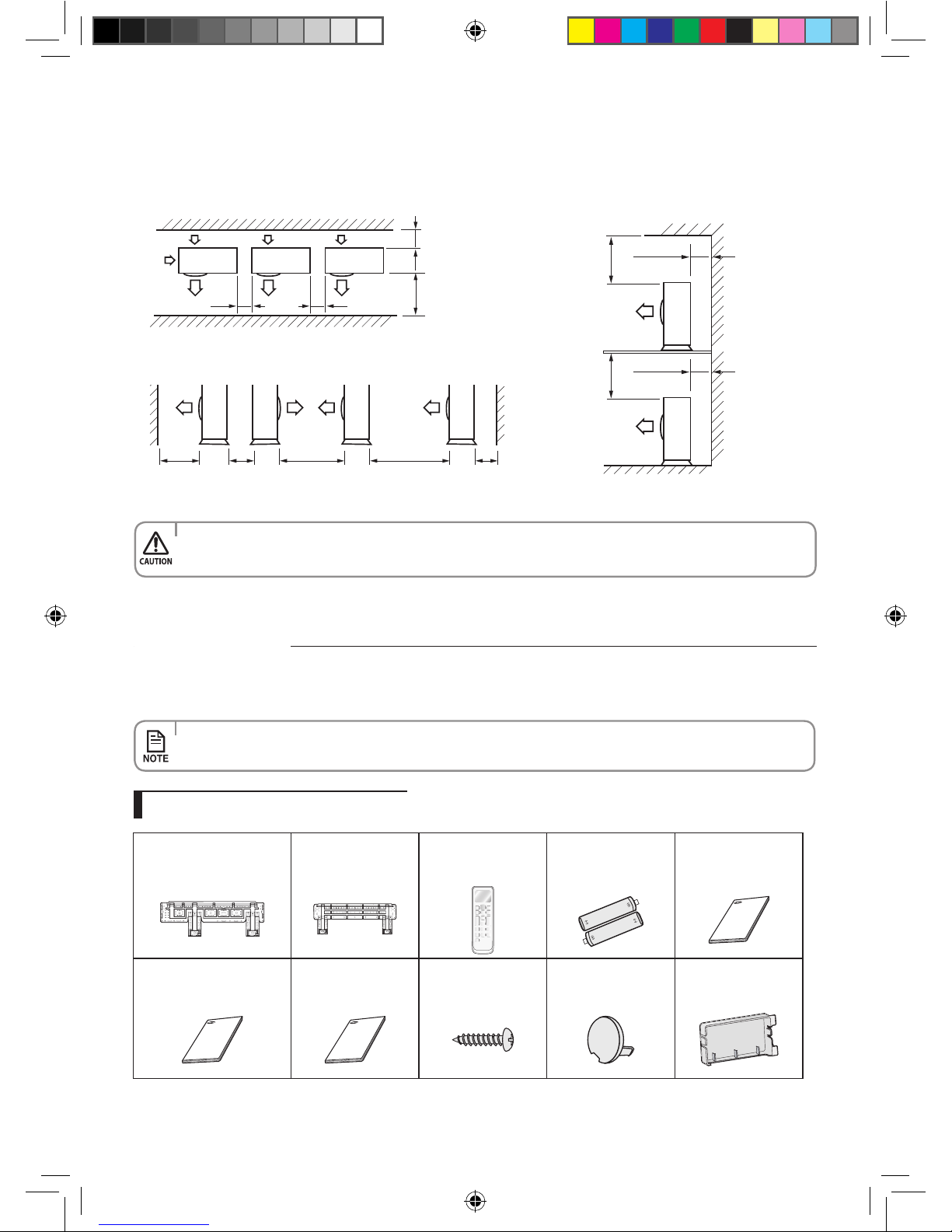
The following accessories are supplied with the air conditioner:
• The number of each accessory is indicated in parentheses.
Accessories in the indoor unit case
Accessories
(Unit : mm)
Installation Plate (1)
AR07/09/12HSSDB (03 frame)
AR09/12HSSDA (04 frame)
Installation Plate (1)
18/24 (05 frame)
Remote controller (1)
Batteries for Remote
controller (2)
User’s Manual (1)
Installation Manual (1) Wi-Fi Manual (1)
M4 x 10 Tapped
Screws(2)
Cap Screws(3)
Case Sub PCB
ARHSSDB
English-7
A3050 EU_IM_DB68-04212A_HP_EN.indd 7 2013-10-23 16:31:11

Accessories in the outdoor unit case
• The are nuts are attached to the end of each pipe of an evaporator or a service port.
Use the nuts when connecting the pipes.
• The assembly cable is optional. If it is not supplied, use the standard cable.
• The drain plug and rubber leg are only included when the air conditioner is supplied without the assembly
pipe as seen in the picture below.
2-wire
Assembly Cable (1)
3-wire
Assembly Cable (2)
Drain Plug (1) Rubber Leg (4)
Tools required for installation
General Tools
• Vacuum Pump(Backward owing prevention) • Manifold Gauge • Stud Finder
• Torque Wrench • Pipe Cutter • Reamer • Pipe Bender • Spirit Level
• Screw Driver • Spanner • Drill • L Wrench • Measuring Tape
Tools for test operations
• Thermometer • Resistance Meter • Electroscope
Optional accessories
The following connection accessories are optional. If they are not supplied, you should obtain them before installing the air
conditioner.
• If these accessories are supplied, they will be in the accessory box.
Insulated
Assembly Pipe,
Ø6.35mm (1)
Insulated Assembly
Pipe, Ø9.52mm (1)
09/12
Insulated Assembly
Pipe, Ø12.70mm (1)
18
Insulated Assembly
Pipe, Ø15.88mm (1)
24
PE T3 Foam Tube
Insulation (1)
Vinyl Tapes (2) Drain Plug (1)
Rubber Legs (4) Pipe Clamps A (3) Pipe Clamps B (3) Cement Nails (6)
M4 x 25 Tapped
Screws (6)
Drain Hose,
length 2m (1)
Putty 100g (1)
Foam
Insulation(1)
Accessories
If using a multi system, refer to the manual supplied with the outdoor unit.
If using a multi system, refer to the manual supplied with the outdoor unit.
English-8
A3050 EU_IM_DB68-04212A_HP_EN.indd 8 2013-10-23 16:31:11

Fixing the installation plate
You can select the direction of the drain hose depending on where you want to install the indoor unit. Therefore before xing
the installation plate to a wall or a window frame, you must determine the position of the 65mm hole through which the cable,
pipe and hose pass to connect the indoor unit to the outdoor unit.
When facing the wall, the pipe and cable can be connected from the:
A
C
B
D
D
Direction of pipe
1. Determine the position of the pipe and drain hose hole as seen in the picture and drill the hole with an inner diameter
of 65mm so that it slants slightly downwards.
• Right (A)
• Left (B)
• Underside_right (C)
• Rear_right or left (D)
Wall
<20mm
Plastic
Anchor
2. Fix the indoor unit.
If you x the indoor unit on a wall
(1) Fix the installation plate to the wall giving attention to the weight of the indoor unit.
If you x the indoor unit on a window frame
(1) Determine the positions of the wooden uprights to be attached to the window frame.
(2) Attach the wooden uprights to the window frame giving attention to the weight of the indoor unit.
(3) Attach the installation plate to the wooden upright using tapping screws.
If you x the indoor unit on a gypsum board
(1) Use stud nder to nd out locations of the studs.
(2) Fix the plate hanger on two studs.
• If you mount the plate to a concrete wall using plastic anchors, make sure that gaps
between the wall and the plate, created by projected anchor, is less than 20mm.
• Search for other spots if there are less than two studs, or the distance between the studs are dierent from the
plate hanger.
• Fix the installation plate without inclining to one side.
• Make sure that a wall can withstand the weight of the product. If you install the product in a place where it is not
strong enough to withstand the product weight, the unit could fall and cause injury.
• Make sure to drill only one hole after choosing the
direction of the pipe.
(Unit : mm)
Model A B C D
AR07/09/12HSSDB
AR09/12HSSDA
0 241 30 0
18/24
5 161 52 5
B
A
D
C
B
A
D
C
Pipe hole (Ø65 mm) Pipe hole (Ø65 mm)
English-9
A3050 EU_IM_DB68-04212A_HP_EN.indd 9 2013-10-23 16:31:11
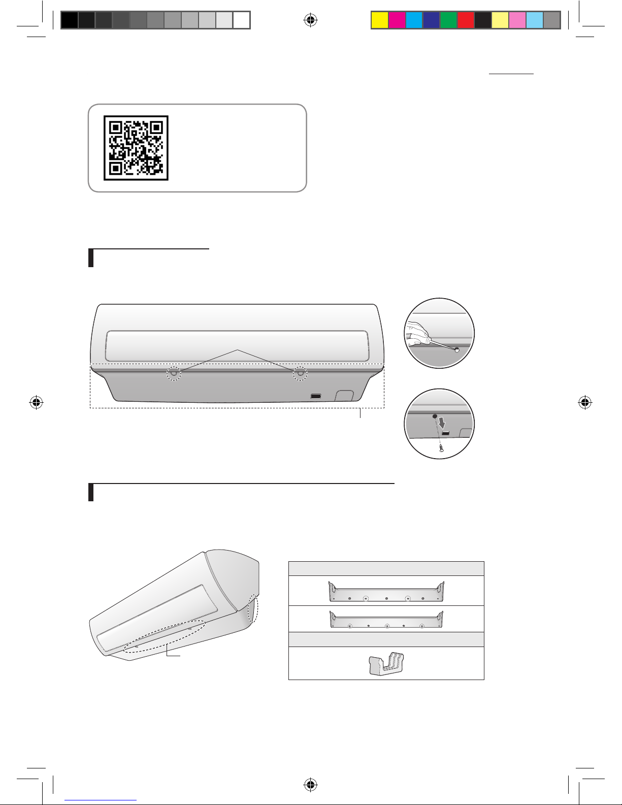
Disassembling/Assembling the Cover panel for indoor unit installation
In order to install the indoor unit, you must disassemble the cover panel rst. Please proceed following
instructions to disassemble and assemble the cover panel. Hooks (on the cover panel) may get damaged if you
apply excessive force as you disassemble and assemble the cover panel. Please follow the following instructions.
Removing the screws
Cover panel is assembled on the bottom part of the indoor unit (as shown in the illustration) and it is fastened
with screws. Remove the Cap screw rst and unfasten the screws so that you can disassemble the cover panel.
Cap Screw
<Remove the Cap screw>
<Unfasten the screw>
Cover Panel
Removing the Cover panel (Before mounting the indoor unit)
Cover panel is xed to a main body of the product with hooks on two sides and central part as shown in the
illustration. Release the hooks on the sides rst, and then release the hooks on the central part.
Check the location of the hooks before removing the cover panel.
Please scan
this QR code for detail
video of indoor unit
installation.
f Location of the hooks on the central part
For specic Hook location and quantity, please refer
to cover panel with indicating arrows based on
physical goods.
Number and location of the hooks
Hook
Side
part
Central part
English-10
A3050 EU_IM_DB68-04212A_HP_EN.indd 10 2013-10-23 16:31:12
 Loading...