

Page 1

Air conditioner
Installation manual
ARHS/JS
• Thank you for purchasing this Samsung air conditioner.
• Before operating this unit, please read this Installation manual carefully and retain it for future
reference.
A3050_EU_Best model_IM_DB68-06152A-00_EN.indd 32 2016/4/20 14:10:13
Page 2

Air conditioner
Installation manual
ARHS/JS
• Thank you for purchasing this Samsung air conditioner.
• Before operating this unit, please read this Installation manual carefully and retain it for future
reference.
A3050_EU_Best model_IM_DB68-06152A-00_EN.indd 1 2016/4/20 14:10:13
Page 3

2
English
Contents
Installation 3
Safety Information on Installation 3
Preparation 5
Step 1.1 Choosing the installation location
Step 1.2 Checking and preparing accessories and tools
Step 1.3 Drilling a hole through the wall
Step 1.4 Taping the pipes, cables, and drain hose
Indoor Unit Installation 9
Step 2.1 Disassembling the cover panel
Step 2.2 Disassembling the installation plate
Step 2.3 Connecting the power and communication cables (assembly cable)
Step 2.4 Optional: Extending the power cable
Step 2.5 Installing and connecting the drain hose
Step 2.6 Optional: Extending the drain hose
Step 2.7 Optional: Changing the direction of the drain hose
Step 2.8 Installing and connecting the assembly pipes to the refrigerant pipes (assembly pipe)
Step 2.9 Shortening or extending the refrigerant pipes (assembly pipe)
Step 2.10 Fixing the installation plate
Step 2.11 Fixing the indoor unit to the installation plate
Step 2.12 Assembling the cover panel
Outdoor Unit Installation 17
Step 3.1 Fixing the outdoor unit in place
Step 3.2 Connecting the power and communication cables and the refrigerant pipes
Step 3.3 Evacuating the air
Step 3.4 Adding refrigerant
Step 3.5 Important information regulation regarding the refrigerant used
Installation Inspection 21
Step 4.1 Performing the gas leak tests
Step 4.2 Running the Smart Install mode
Step 4.3 Performing final check and trial operation
Sub PCB installation(optional) 24
For information on Samsung’s environmental commitments and product specific regulatory
obligations e.g. REACH visit: samsung.com/uk/aboutsamsung/samsungelectronics/
corporatecitizenship/data_corner.html
A3050_EU_Best model_IM_DB68-06152A-00_EN.indd 2 2016/4/20 14:10:13
Page 4

3
English
Installation
Carefully follow the precautions listed below because
they are essential to guarantee the safety of both the air
conditioner and the workers.
• Always disconnect the air conditioner from the power
supply before servicing it or accessing its internal
components.
• Verify that installation and testing operations are
performed by qualified personnel.
• Verify that the air conditioner is not installed in an
easily accessible area.
General information
• Carefully read the content of this manual before
installing the air conditioner and store the manual in
a safe place in order to be able to use it as reference
after installation.
• For maximum safety, installers should always carefully
read the following warnings.
• Store the operation and installation manual in a safe
location and remember to hand it over to the new
owner if the air conditioner is sold or transferred.
• This manual explains how to install an indoor unit
with a split system with two SAMSUNG units. The use
of other types of units with different control systems
may damage the units and invalidate the warranty.
The manufacturer shall not be responsible for damages
arising from the use of non compliant units.
• The manufacturer shall not be responsible for damage
originating from unauthorised changes or the improper
connection of electric and requirements set forth in the
“Operating limits” table, included in the manual, shall
immediately invalidate the warranty.
• The air conditioner should be used only for the
applications for which it has been designed: the indoor
unit is not suitable to be installed in areas used for
laundry.
• Do not use the units if damaged. If problems occur,
switch the unit off and disconnect it from the power
supply.
• In order to help prevent electric shocks, fires or
injuries, always stop the unit, disable the protection
switch and contact SAMSUNG’s technical support if
the unit produces smoke, if the power cable is hot or
damaged or if the unit is very noisy.
• Always remember to inspect the unit, electric
connections, refrigerant tubes and protections
regularly. These operations should be performed by
qualified personnel only.
• The unit contains moving parts, which should always
be kept out of the reach of children.
• Do not attempt to repair, move, alter or reinstall the
unit. If performed by unauthorised personnel, these
operations may cause electric shocks or fires.
• Do not place containers with liquids or other objects
on the unit.
• All the materials used for the manufacture and
packaging of the air conditioner are recyclable.
• The packing material and exhaust batteries of the
remote control (optional) must be disposed of in
accordance with current laws.
• The air conditioner contains a refrigerant that has
to be disposed of as special waste. At the end of its
life cycle, the air conditioner must be disposed of in
authorised centres or returned to the retailer so that it
can be disposed of correctly and safely.
Installation of the unit
• IMPORTANT: When installing the unit, always
remember to connect first the refrigerant tubes, then
the electrical lines. Always disassemble the electric
lines before the refrigerant tubes.
• Upon receipt, inspect the product to verify that it has
not been damaged during transport. If the product
appears damaged, DO NOT INSTALL it and immediately
report the damage to the carrier or retailer (if the
installer or the authorised technician has collected the
material from the retailer.)
• After completing the installation, always carry out a
functional test and provide the instructions on how to
operate the air conditioner to the user.
• Do not use the air conditioner in environments with
hazardous substances or close to equipment that
release free flames to avoid the occurrence of fires,
explosions or injuries.
• Our units must be installed in compliance with the
spaces indicated in the installation manual to ensure
either accessibility from both sides or ability to
perform routine maintenance and repairs. The units’
components must be accessible and that can be
disassembled in conditions of complete safety either
for people or things. For this reason, where it is not
observed as indicated into the Installation Manual, the
cost necessary to reach and repair the unit (in safety,
as required by current regulations in force) with slings,
Safety Information on Installation
Installation
A3050_EU_Best model_IM_DB68-06152A-00_EN.indd 3 2016/4/20 14:10:13
Page 5
4
English
Installation
trucks, scaffolding or any other means of elevation
won’t be considered in-warranty and will be charged
to end user.
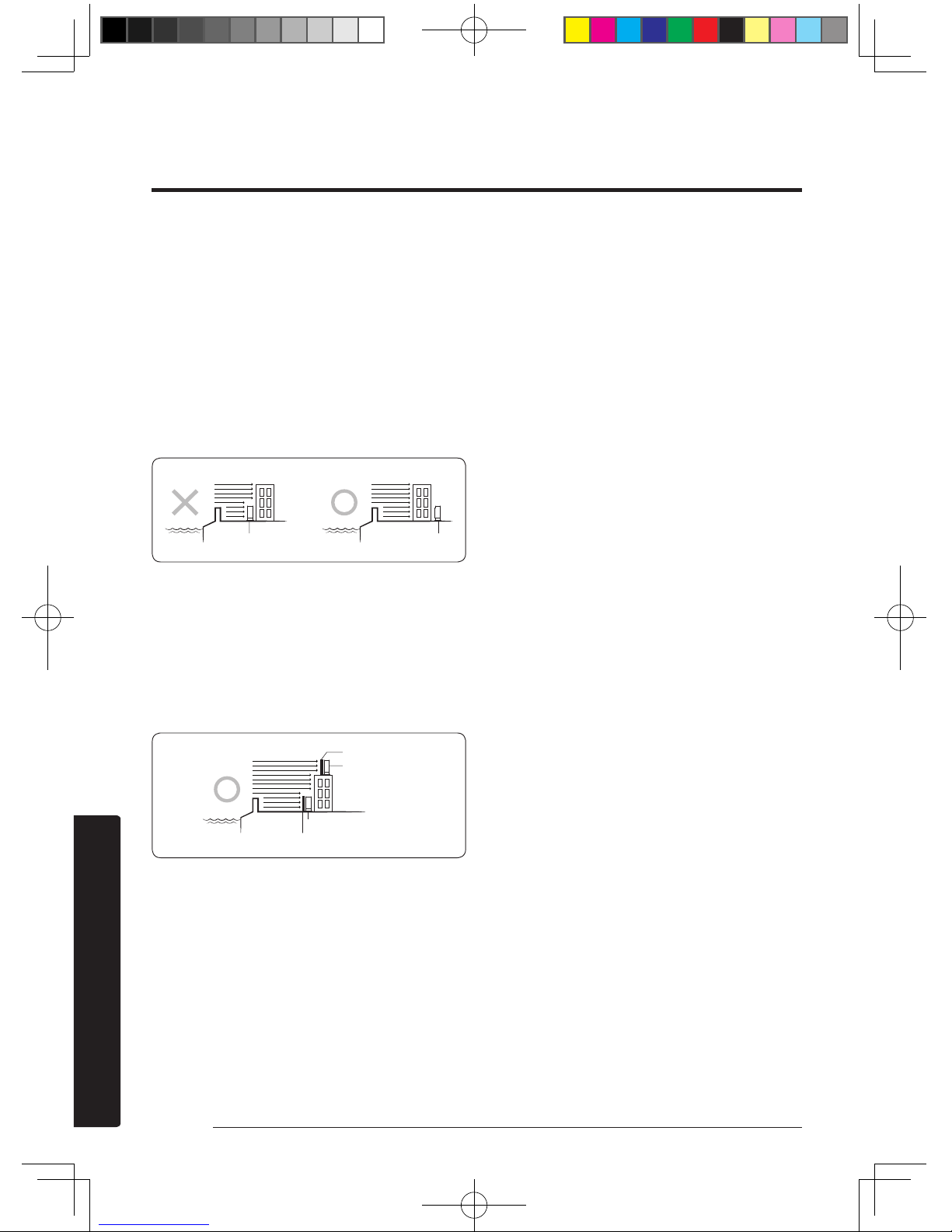
• When installing the outdoor unit at the seaside, make
sure that it is not directly exposed to sea breeze. If
you cannot find an adequate place free from direct
sea breeze, construct a protection wall or a protective
fence.
– Install the outdoor unit in a place (such as near
buildings etc.) where it can be protected from sea
breeze. Failure to do so may cause a damage to the
outdoor unit.
• If you cannot avoid installing the outdoor unit at the
seaside, construct a protection wall around to block the
sea breeze.
• Construct a protection wall with a solid material such
as concrete to block the sea breeze. Make sure that the
height and the width of the wall are 1.5 times larger
than the size of the outdoor unit. Also, secure a space
larger than 600 mm between the protection wall and
the outdoor unit for exhausted air to ventilate.
• Install the unit in a place where water can drain
smoothly.
• If you have any difficulty finding installation location
as prescribed above, contact your manufacturer for
details.
• Be sure to clean the sea water and the dust on the heat
exchanger of the outdoor unit and apply a corrosion
inhibitor on it. (At least once in a year.)
Power supply line, fuse, or circuit
breaker
• Always make sure that the power supply is compliant
with current safety standards. Always install the air
conditioner in compliance with current local safety
standards.
• Always verify that a suitable grounding connection is
available.
• Verify that the voltage and frequency of the power
supply comply with the specifications and that the
installed power is sufficient to ensure the operation of
any other domestic appliance connected to the same
electric lines.
• Always verify that the cut-off and protection switches
are suitably dimensioned.
• Verify that the air conditioner is connected to the
power supply in accordance with the instructions
provided in the wiring diagram included in the manual.
• Always verify that electric connections (cable entry,
section of leads, protections…) are compliant with
the electric specifications and with the instructions
provided in the wiring scheme. Always verify that all
connections comply with the standards applicable to
the installation of air conditioners.
Sea breeze
Protection wall
Outdoor unit
Sea
Outdoor unit
Protection wall
Sea breeze
Outdoor unit
Sea
Sea breeze
Sea
Outdoor unit
A3050_EU_Best model_IM_DB68-06152A-00_EN.indd 4 2016/4/20 14:10:14
Page 6
5
English
Installation
Preparation
Step 1.1 Choosing the installation
location
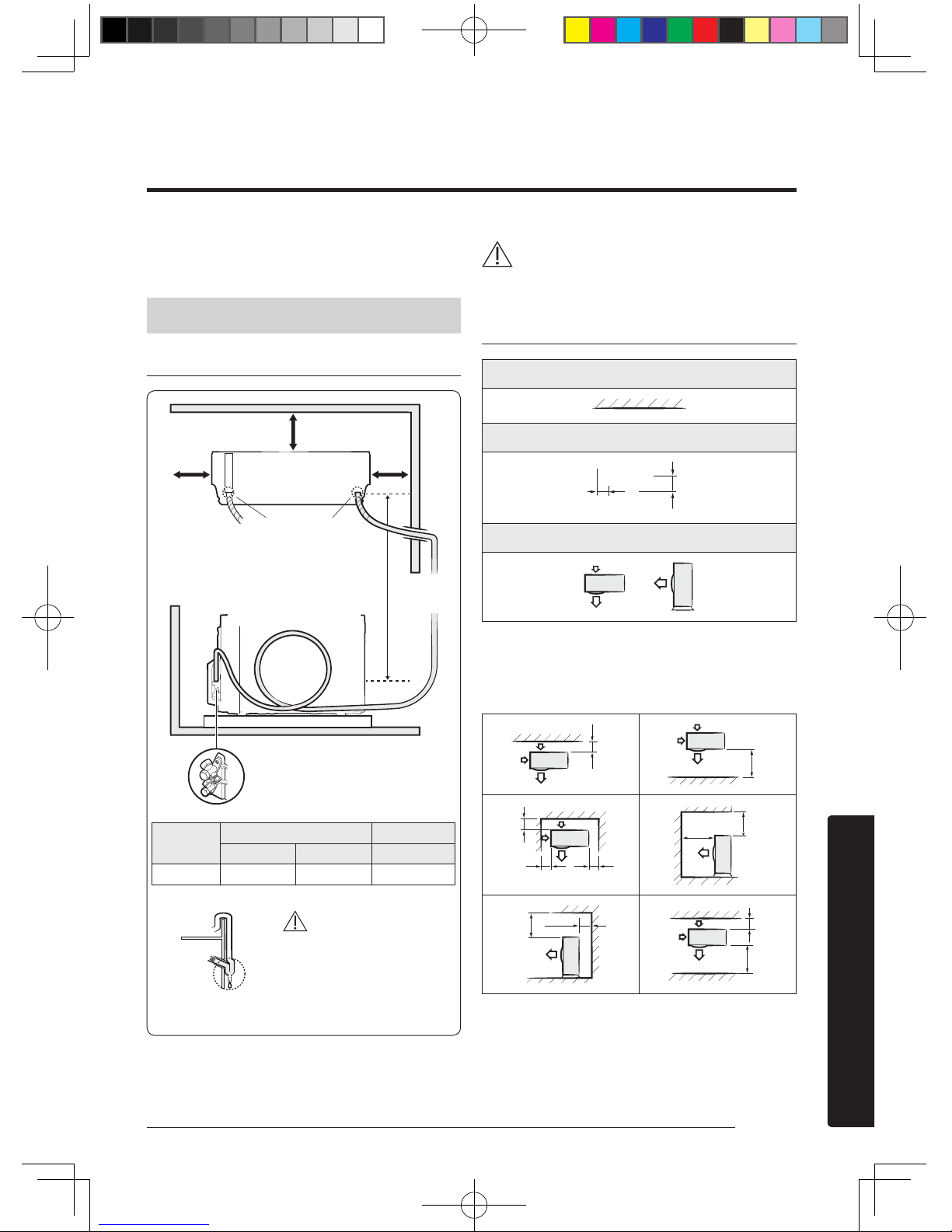
If using a multi system, install as described in the
installation manual supplied with the outdoor unit.
Overview of installation location requirements
CAUTION
CAUTION
• Comply with the length and height limits described in
the figure above.
Minimum clearances for the outdoor unit
Wall
Minimum clearance in mm
300
600
Air flow direction
When installing 1 outdoor unit
(6 cases)
(Unit: mm)
300
1500
300
150 600
1500
2000
500
300
300 1500
(Unit : m)
Model
Pipe length Pipe height
Minimum Maximum Maximum
09/12 3 15 8
100 mm or more
125 mm
or more
125 mm
or more
Drain hose hole
You can select the direction of
draining (left or right).
Maximum pipe height: 8 m
Maximum pipe length: 15 m
Make at least one round to
reduce noise and vibration.
The actual units may look different from
the images depicted here.
Make a U-trap (A) on the
pipe (which is connected to
the indoor unit) at outer wall
and cut the bottom part of
the insulation (about 10 mm)
to prevent rainwater from
getting inside through the
insulation.
Outdoor
Unit
Outer wall
Indoor
Unit
Cut insulation to have
rainwater drained
Top view
Side view
A3050_EU_Best model_IM_DB68-06152A-00_EN.indd 5 2016/4/20 14:10:15
Page 7
6
English
Installation
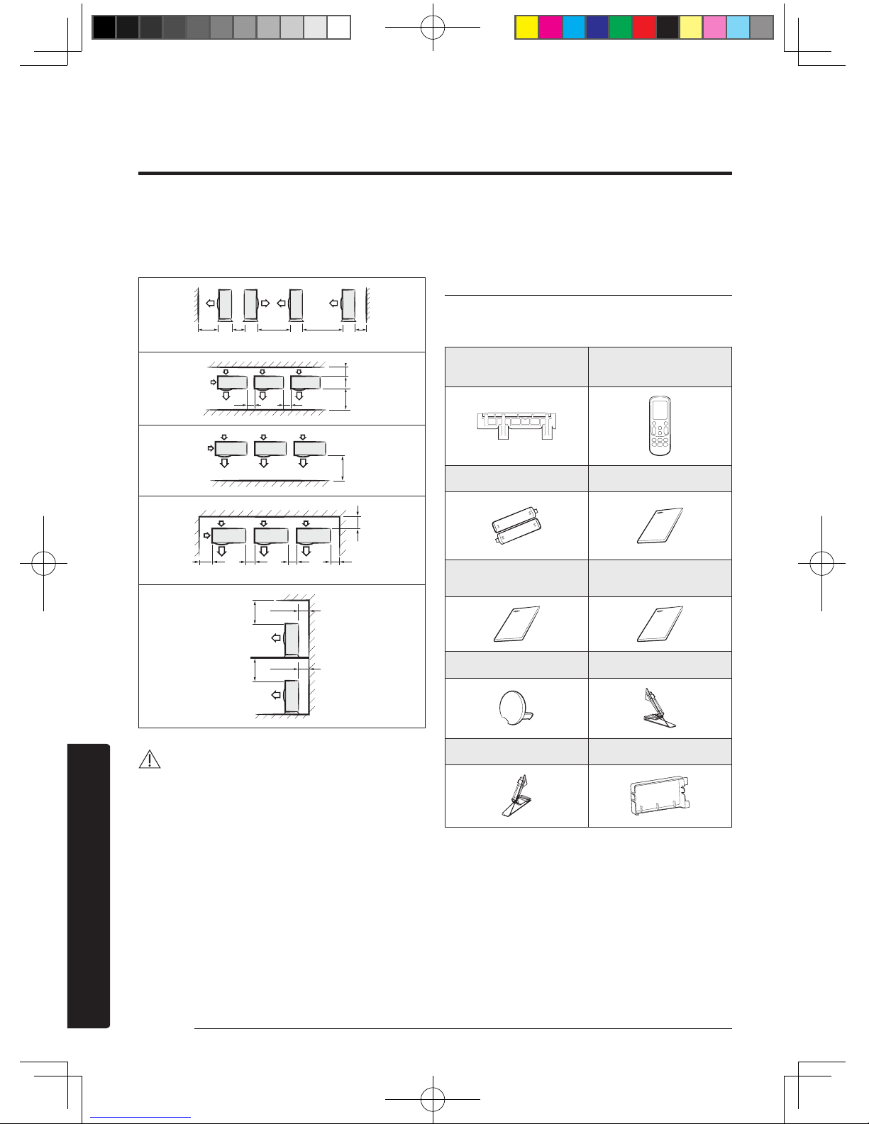
When installing more than 1 outdoor unit
(5 cases)
(Unit: mm)
1500 600 3000 2003000
3001500
600 600
1500
300
300 600 600 600
500
300
500
300
CAUTION
• If the outdoor unit is installed with any insufficient
clearance, it may generate sound and affect the whole
product.
• Be sure to install the outdoor unit in a level place
where its vibration does not affect the whole product.
Step 1.2 Checking and preparing
accessories and tools
Accessories
Accessories in the indoor unit package
Installation plate (1) Remote control (1)
Remote control battery (2) User Manual (1)
Installation Manual (1)
Smart A/C application Manual
(1)
Cap screw (2) Guide Left(1)
Guide Right(1) Case Sub PCB (1)
A3050_EU_Best model_IM_DB68-06152A-00_EN.indd 6 2016/4/20 14:10:15
Page 8

7
English
Installation
If using a multi system, refer to the manual supplied
with the outdoor unit.
Optional accessories
Insulated assembly pipe,
Ø 6.35 mm (1)
Insulated assembly pipe,
Ø 9.52 mm (1)
09/12
Drain Hose, 2 m long (1) Foam Insulation(1)
Pipe clamp A (3) Pipe clamp B (3)
Vinyl tape (2) PE T3 foam tube insulation (1)
Putty 100 g (1) Drain plug (1)
M4 x 25 tapped screw (6) Cement nail (6)
3-wire assembly cable (2) 2-wire assembly cable (1)
Accessories in the outdoor unit package
Rubber leg (4)
NOTE
• A flare nut is attached to the end of each pipe of an
evaporator or a service port. Use flare nuts when
connecting the pipes.
• Wire assembly cables are optional. If they are not
supplied, use standard cables.
• The drain plug and the rubber legs are included only
when the air conditioner is supplied without assembly
pipes.
• If these accessories are supplied, they are in the
accessory package or outdoor unit package.
Tools
General tools
• Vacuum pump
(Backward flowing
prevention)
• Manifold gauge
• Stud finder
• Torque wrench
• Pipe cutter
• Reamer
• Pipe bender
• Spirit level
• Screwdriver
• Spanner
• Drill
• L-wrench
• Measuring tape
Tools for test operation
• Thermometer
• Resistance meter
• Electroscope
Step 1.3 Drilling a hole through the
wall
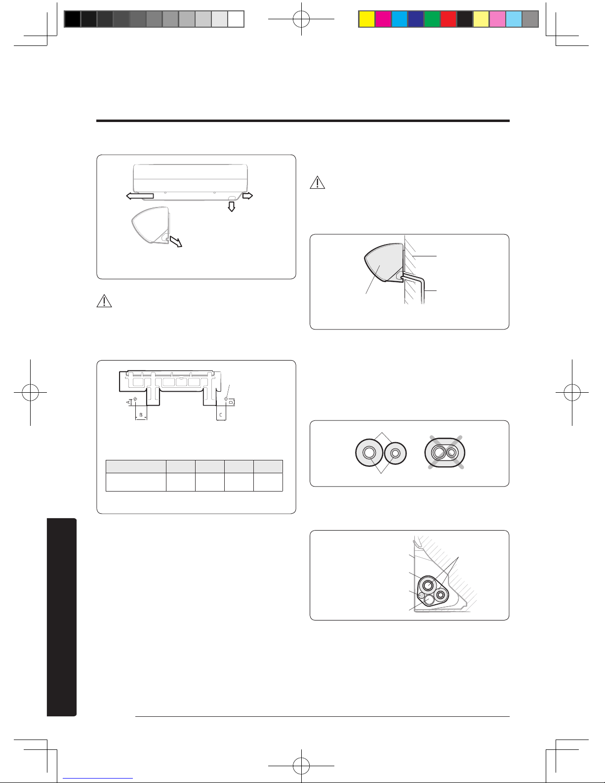
Before fixing the installation plate to a wall and then fixing
the indoor unit to the installation plate, a window frame,
or a gypsum board, you must determine the position of a
hole (with 65 mm inner diameter) through which the pipe
bundle (consisting of power and communication cables,
refrigerant pipes, and drain hose) will pass and then drill
that hole.
1 Determine the position of a 65 mm hole in
consideration of the possible directions of the pipe
bundle and the minimum distances between the hole
and the installation plate.
A3050_EU_Best model_IM_DB68-06152A-00_EN.indd 7 2016/4/20 14:10:16
Page 9
8 English
Installation
Left
CAUTION
• If changing the pipe direction from left to right, do not
drastically bent it but slowly turn it in the opposite
direction as shown. Otherwise, the pipe may be
damaged in the process.
2 Drill the hole.
CAUTION
• Be sure to drill only one hole.
• Make sure that the hole slants downwards so that the
drain hose slants downwards to drain water well.
Step 1.4 Taping the pipes, cables, and
drain hose
1 Wrap foam insulation on parts without insulation on
the ends of the refrigerant pipes, as shown in the
figure. This wrapping minimises condensation problem.
2 Wind the refrigerant pipes, power cable,
communication cable and drain hose with vinyl tape to
make a pipe bundle.
<Possible directions of the pipe bundle>
Left Right
Rear right or left
Bottom right
Wall
Drain hose
Indoor unit
<The hole slants downwards>
Insulation
Refrigerant pipes
Refrigerant pipes
(assembly pipe)
Installation plate
Vinyl tape
Power and communication cables
(assembly cable)
Drain hose
Pipe bundle hole
(Unit : mm)
Model A B C D
09/12 36 147 81 36
Pipe bundle hole: Ø 65 mm
<Minimum distances between the hole and the
installation plate>
A3050_EU_Best model_IM_DB68-06152A-00_EN.indd 8 2016/4/20 14:10:17
Page 10
9English
Installation
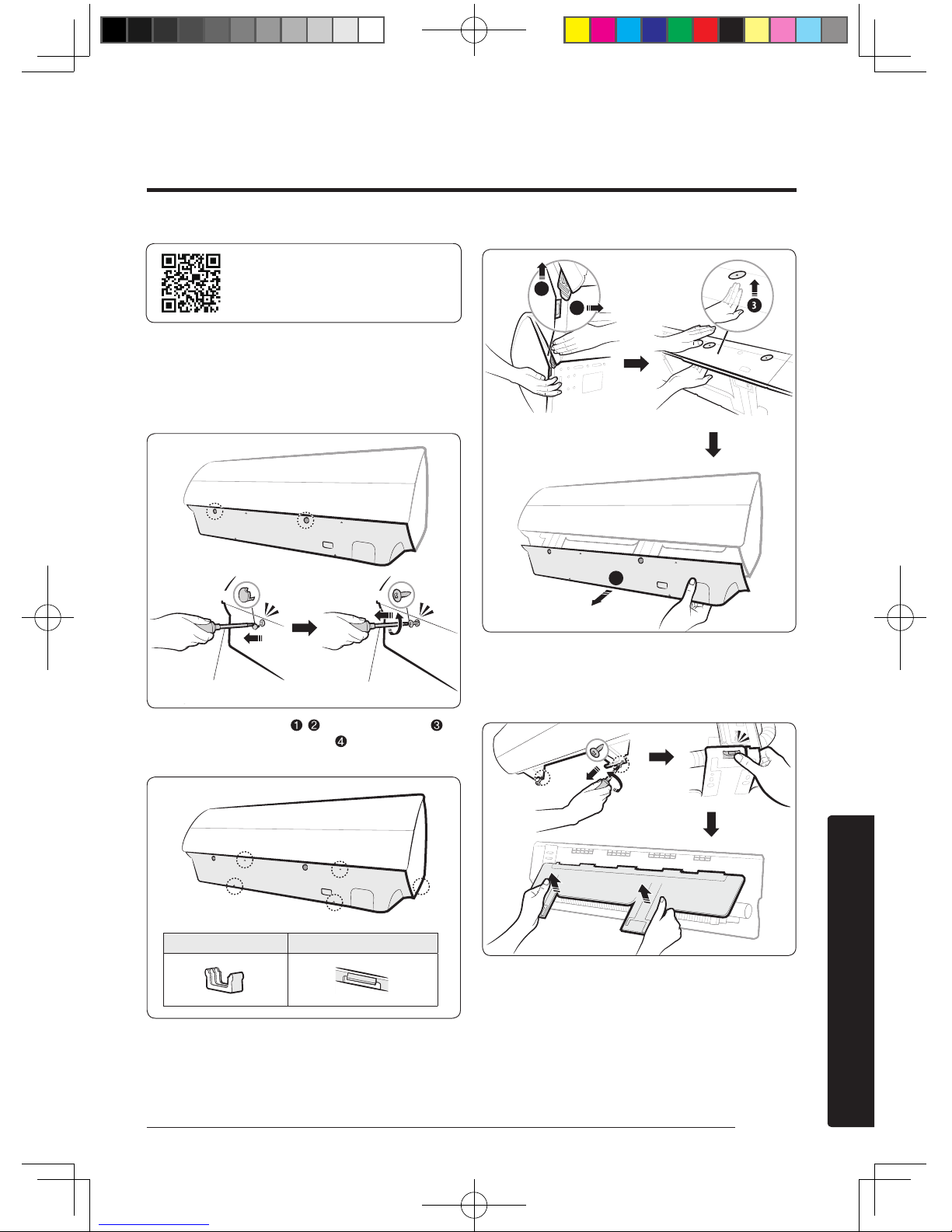
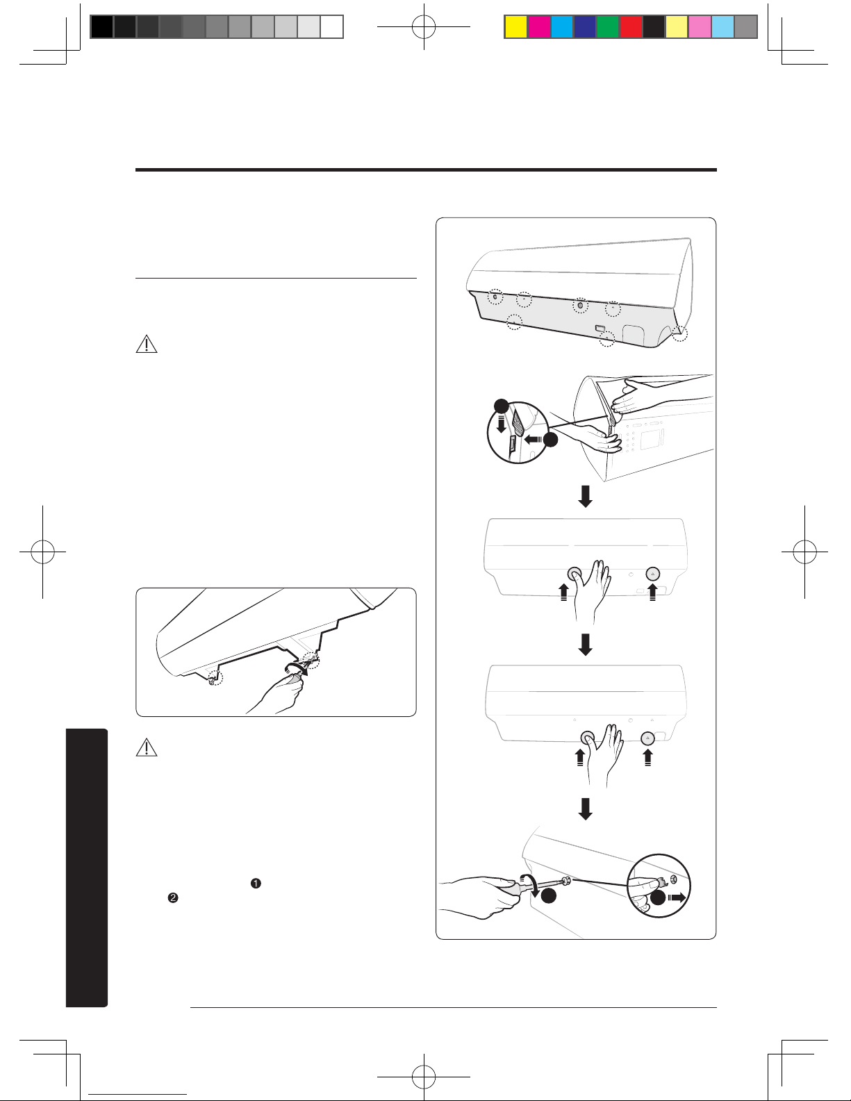
Step 2.1 Disassembling the cover
panel
1 Remove the cap screws, then the screws.
2 Unlock the side hooks ( , ), then centre hooks ( ).
Then unlock the bottom hooks ( ) to pull out the
cover panel.
B
B
C
A
A
1
2
4
Step 2.2 Disassembling the
installation plate
Indoor Unit Installation
Please scan this QR code for detail
video of indoor unit installation.
Cap screw
Phillips screwdriver
Screw
Flat-head screwdriver
Centre hook (A) Bottom/Side hook (B/C)
A3050_EU_Best model_IM_DB68-06152A-00_EN.indd 9 2016/4/20 14:10:18
Page 11
10 English
Installation
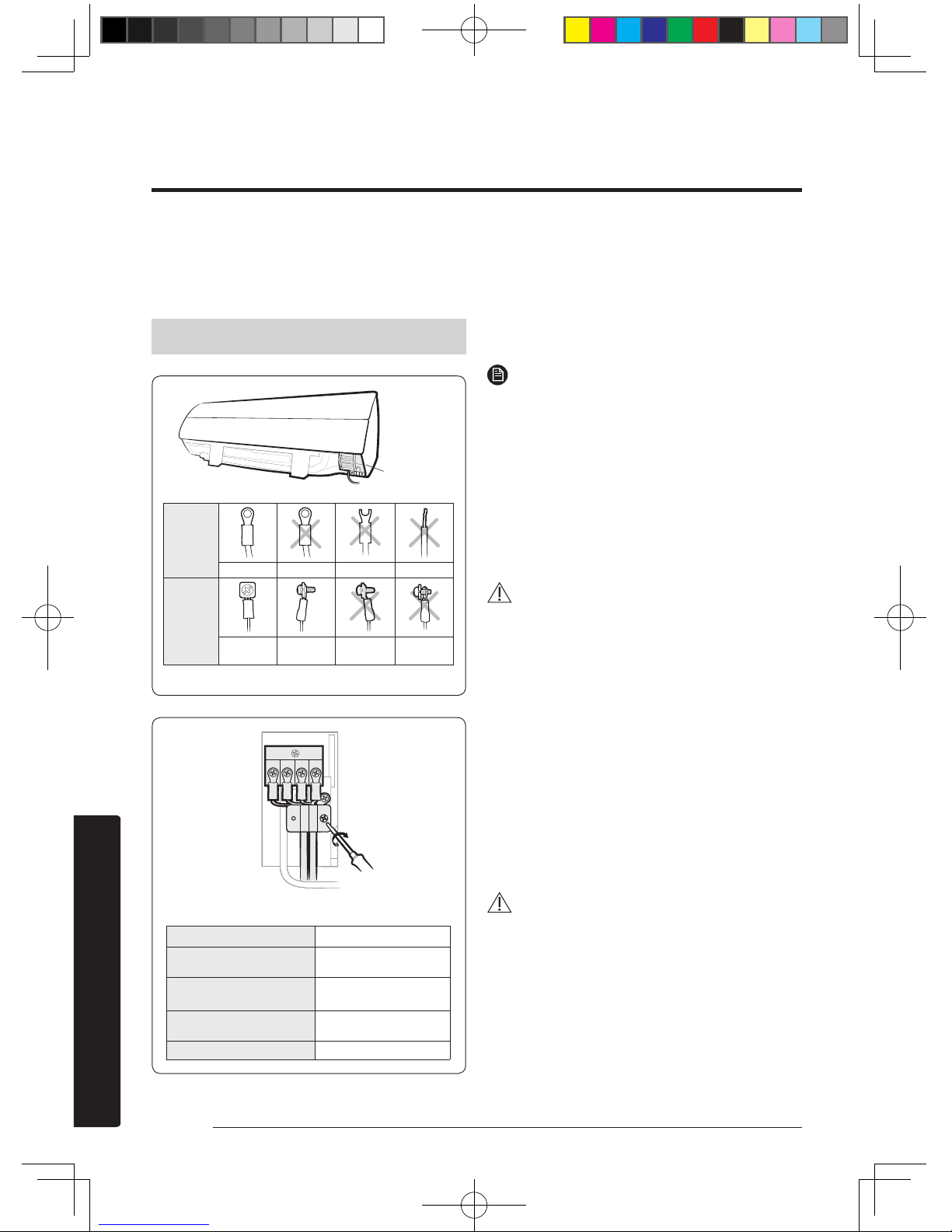
Step 2.3 Connecting the power and
communication cables (assembly
cable)
If using a multi system, install as described in the
installation manual supplied with the outdoor unit.
1(L)2(N) F1 F2
• When performing electrical and earthing works,
be sure to comply with the 'technical standards of
electrical installations' and the 'wiring regulations' in
the local regulations.
• Tightentheterminalblockscrewto1.2-1.8N•m(1218kgf•cm).
NOTE
• Each wire is labelled with the corresponding terminal
number.
• Use shield cable (Category 5; less than 50pF/m) for
noisy environmental site.
• Power supply cords of parts of appliances for outdoor
use shall not be lighter than polychloroprene sheathed
flexible cord. (Code designation IEC: 60245 IEC 66/
CENELEC: H07RN-F, IEC: 60245 IEC 57/CENELEC:
H05RN-F)
• Power & Communication cable shall not exceed 30m.
CAUTION
• For the terminal block wiring, use a wire with a
ring terminal socket only. Regular wires without a
ring terminal socket may become a hazard due to
overheating of the electrical contact during installation.
• If you need to extend the pipe, be sure to extend the
cable too. The maximum length of each of the cable
and pipe used should not exceed 15 metres .
• Do not connect two or more different cables to extend
the length. This connection may cause fire.
• Each circular terminal must match the size of its
corresponding screw in the terminal block.
• After connecting the cables, make sure that terminal
numbers on the indoor and outdoor units match.
• Ensure that power and communication cables are
separated, they must not be in the same cable.
WARNING
• Connect the wires firmly so that wires cannot be pulled
out easily. (If they are loose, it could cause burn-out of
the wires.)
Model
09/12
Power cable
(Outdoor unit)
3G X 1.5 mm²,
H07RN-F
Outdoor-to-indoor power
cable
3G X 1.0 mm²,
H07RN-F
Communication cable
2 X 0.75 mm²,
H05RN-F
Type GL 20A
Before
connecting
Correct Upside down Damaged Non-circular
After
connecting
Correct Correct
Upside down Non-fitted
(Front view) (Side view)
<Circular terminal>
Control box
Fasten the screws for the wire holders.
A3050_EU_Best model_IM_DB68-06152A-00_EN.indd 10 2016/4/20 14:10:19
Page 12
11English
Installation
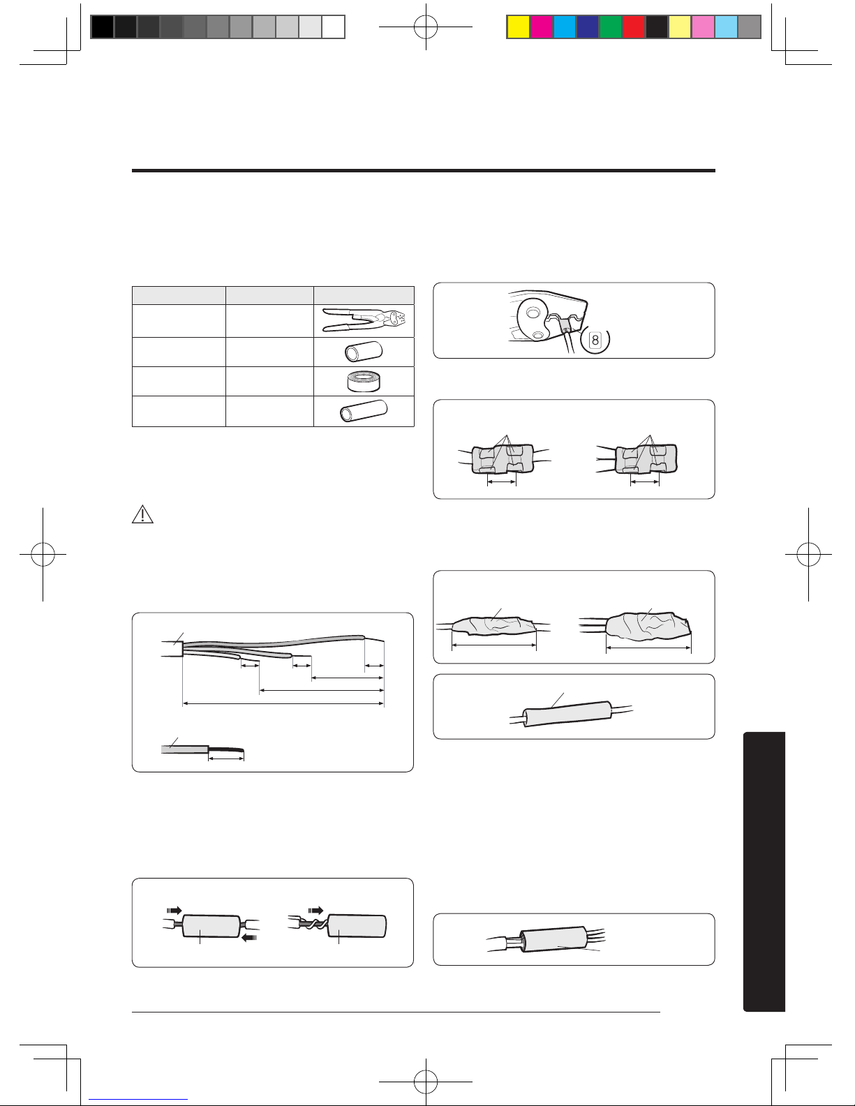
Step 2.4 Optional: Extending the
power cable
1 Prepare a compressor and the following tools.
Tools Spec Shape
Crimping pliers MH-14
Connection sleeve
(mm)
20xØ7.0 (HxOD)
Insulation tape Width 18 mm
Contraction tube
(mm)
50xØ8.0 (LxOD)
2 As shown in the figure, peel off the shields from the
rubber or wire of the power cable.
• Peel off 20 mm of the wire shields of the tube
installed already.
CAUTION
• For information about the power cable
specifications for indoor and outdoor units, refer
to the installation manual.
• After peeling off the tube wire, you must insert a
contraction tube.
20 20
20
20
60
120
180
3 Insert both sides of core wire of the power cable into
the connection sleeve.
• Method 1: Push the core wire into the sleeve from
both sides.
• Method 2: Twist the wire cores together and push
it into the sleeve.
4 Using a compressor, compress the two points and flip
it over and compress another two points in the same
location.
• The compression dimension should be 8.0.
• After compressing it, pull both sides of the wire to
make sure it is firmly pressed.
5 Wrap it with the insulation tape twice or more and
position your contraction tube in the middle of the
insulation tape.
A total of three or more layers of insulation is required.
6 Apply heat to the contraction tube to contract it.
7 After tube contraction work is completed, wrap it with
the insulation tape to finish.
• Make sure that the connection parts are not
exposed to outside.
• Be sure to use insulation tape and a contraction
tube made of approved reinforced insulating
materials that have the same level of withstand
voltage with the power cable. (Comply with the
local regulations on extensions.)
Power cable (provided by us)
Wire tube power cable
(Unit: mm)
(Unit: mm)
Method 1
Method 2
Connection sleeve
Connection sleeve
Compression
dimension
Compress it 4 times
Compress it 4 times
Method 1
Method 2
5 mm
5 mm
Insulation tape
Method 1 Method 2
Insulation tape
40 mm
35 mm
Contraction tube
Insulation tape
A3050_EU_Best model_IM_DB68-06152A-00_EN.indd 11 2016/4/20 14:10:20
Page 13
12 English
Installation
WARNING
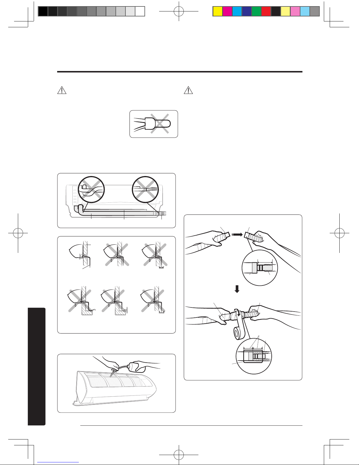
• In case of extending the electric wire, please DO NOT
use a round-shaped pressing socket.
– Incomplete wire
connections can cause
electric shock or a fire.
Step 2.5 Installing and connecting the
drain hose
1 Install the drain hose.
2 Pour water into the drain pan. Check whether the hose
is well drained.
CAUTION
• Make sure that the indoor unit is in upright position
when you pour water to check for leakage. Make sure
that the water does not overflow onto the electrical
part.
• If the diameter of the connection hose is smaller than
the product's drain hose, water leakage may occur.
• Inadequate installation may cause water leakage.
• If the drain hose is routed inside the room, insulate the
hose so that dripping condensation does not damage
the furniture or floors.
• Do not box in or cover the drain hose connection.
Drain hose connection must be easily accessible and
serviceable.
Step 2.6 Optional: Extending the drain
hose
(A) (B)
Drain hose Assembly pipe Connection hose
Indoor unit
Drain hose
Wall
5 cm
less
Ditch
Slant downwards Slant upwards Dipped in water
Bent
Too small
clearance
Too small
clearance
Drain hose (A) Extension drain hose (B)
Drain hose
Extension drain hose
20 mm or more
Foam insulation
Vinyl tape
40~45mm
A3050_EU_Best model_IM_DB68-06152A-00_EN.indd 12 2016/4/20 14:10:20
Page 14

13English
Installation
Step 2.7 Optional: Changing the
direction of the drain hose
CAUTION
• Make sure that the indoor unit is in upright position
when you pour water to check for leakage. Make sure
that the water does not overflow onto the electrical
part.
Step 2.8 Installing and connecting
the assembly pipes to the refrigerant
pipes (assembly pipe)
Connect indoor and outdoor units with field-supplied
copper pipes by means of flare connections. Use insulated
seamless refrigeration grade pipe only, (Cu DHP type
according to ISO1337), degreased and deoxidized, suitable
for operating pressures of at least 4200 kPa and for burst
pressure of at least 20700 kPa. Under no circumstances
must sanitary type copper pipe be used.
There are 2 refrigerant pipes of different diameters:
• The smaller one is for the liquid refrigerant
• The larger one is for the gas refrigerant
A short liquid refrigerant pipe and a short gas refrigerant
pipe are already fitted to the air conditioner. The
connection procedure for the refrigerant pipes varies
according to the exit position of each pipe when facing
the wall:
1 Cut out the appropriate knock-out piece (A, B, C) on
the rear of the indoor unit unless you connect the pipe
directly from the rear.
2 Smooth the cut edges.
Drain pan outlet
Rubber cap
Pour water in the direction of arrow.
Direction of the drained water
<Front view>
<Side view>
1 <Front view>
3 <Side view>
Left(A)
Underside(C)
Right(B)
Guide right
or left
2 <Assembling the
hanger screw>
Screw
A3050_EU_Best model_IM_DB68-06152A-00_EN.indd 13 2016/4/20 14:10:21
Page 15
14 English
Installation
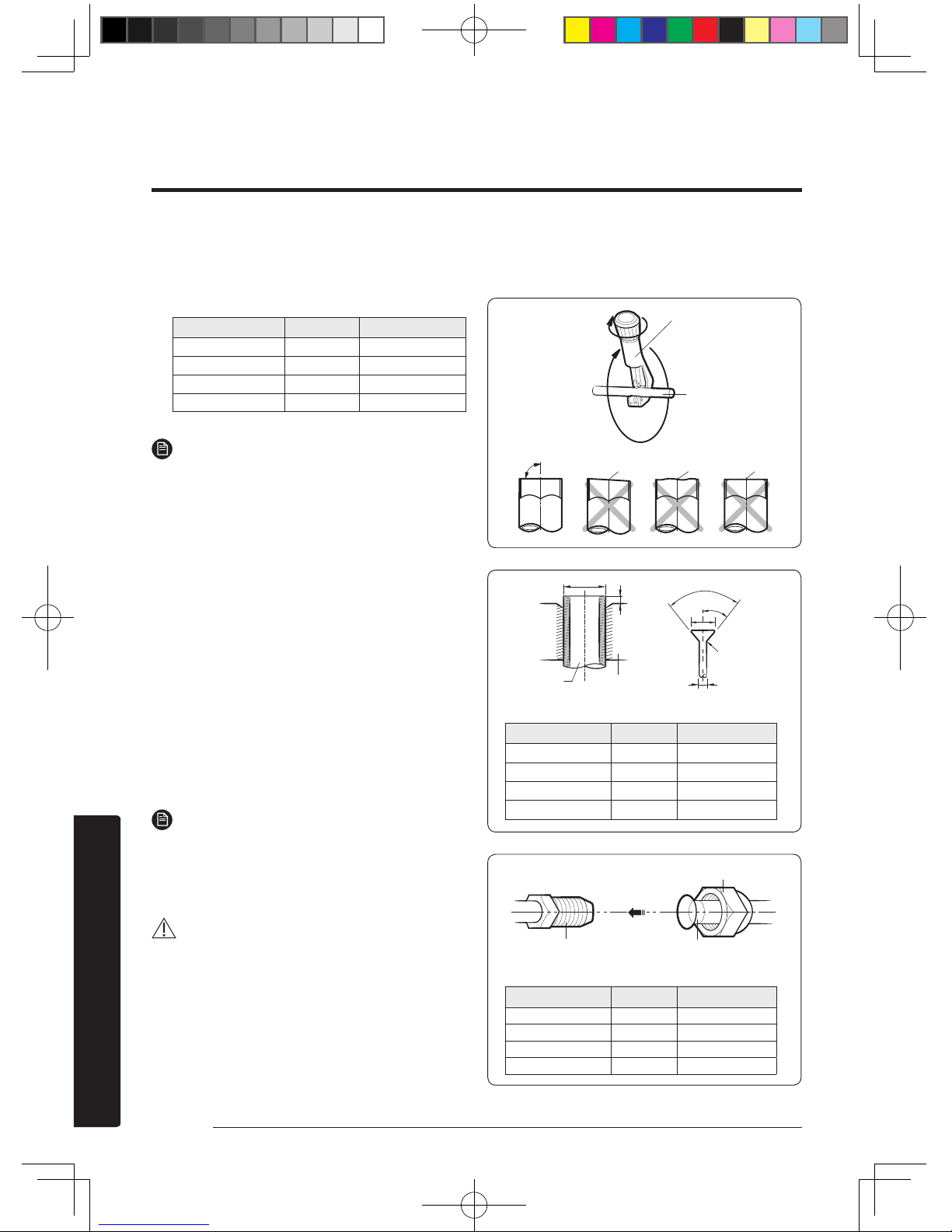
3 Remove the protection caps of the pipes and connect
the assembly pipe to each pipe. Tighten the nuts first
with your hands, and then with a torque wrench,
applying the following torque:
Outer diameter (mm) Torque (N•m) Torque (kgf•cm)
ø 6.35 14 to 18 140 to 180
ø 9.52 34 to 42 350 to 430
ø 12.70 49 to 61 500 to 620
ø 15.88 68 to 82 690 to 830
NOTE
• If you want to shorten or extend the pipes, see
Step 2.9 Shortening or extending the refrigerant
pipes (assembly pipe) on page 14.
4 Cut off the remaining foam insulation.
5 If necessary, bend the pipe to fit along the bottom
of the indoor unit. Then pull it out through the
appropriate hole.
• The pipe should not project from the rear of the
indoor unit.
• The bending radius should be 100 mm or more.
6 Pass the pipe through the hole in the wall.
7 Fix the indoor unit on the wall.Pass the cables, pipes
and hose through the knock-out hole which would be
connected to the outdoor unit .
8 Use 2 screws to fix the indoor unit as shown in the
picture 2.
9 Assemble the Guide into the position of A or B as
shown in the picture 3.
NOTE
• The pipe will be insulated and fixed permanently into
position after finishing the installation and the gas leak
test. For further details. see Step 4.1 Performing the
gas leak tests on page 21.
CAUTION
• Tighten the flare nut with a torque wrench according
to specified method. If the flare nut is over-tightened,
the flare may break and cause refrigerant gas leakage.
• Do not box in or cover the pipe connection. All
refrigerant pipe connection must be easily accessible
and serviceable.
Step 2.9 Shortening or extending the
refrigerant pipes (assembly pipe)
90°
R 0.4 to 0.8
90°±2°
45°±2°
L
D
D
A
(Unit: mm)
Outer diameter (D) Depth (A) Flare dimension (L)
ø 6.35 1.3 8.7 to 9.1
ø 9.52 1.8 12.8 to 13.2
ø 12.70 2.0 16.2 to 16.6
ø 15.88 2.2 19.3 to 19.7
(Unit: mm)
Outer diameter (mm) Torque (N•m) Torque (kgf•cm)
ø 6.35 14 to 18 140 to 180
ø 9.52 34 to 42 350 to 430
ø 12.70 49 to 61 500 to 620
ø 15.88 68 to 82 690 to 830
Pipe cutter
Pipe
Oblique Rough
Burr
Pipe Flare
Indoor outlet pipe
Connecting pipe
Flare nut
A3050_EU_Best model_IM_DB68-06152A-00_EN.indd 14 2016/4/20 14:10:21
Page 16

15English
Installation
CAUTION
• If you need a pipe longer than specified in piping
codes and standards, you must add refrigerant to the
pipe. Otherwise, the indoor unit may freeze.
• While removing burrs, put the pipe face down to make
sure that the burrs do not get in to the pipe.
NOTE
• Excessive torque may cause gas leakage. When
extending the pipe with welding or brazing, ensure
that nitrogen is used during the welding or brazing
process. The joint must be accessible and serviceable.
CAUTION
• Tighten the flare nut at the specified torque. If the flare
nut is over-tightened, it may break to cause leakage of
refrigerant gas.
Step 2.10 Fixing the installation plate
You can install the indoor unit on a wall, window frame, or
gypsum board.
WARNING
• Make sure that the wall, window frame, or gypsum
board can withstand the weight of the indoor unit. If
you install the indoor unit in a place where it is not
strong enough to withstand the unit's weight, the unit
could fall and cause injury.
When fixing the indoor unit on a wall
Fix the installation plate to the wall giving attention to the
weight of the indoor unit.
B
A
D
C
NOTE
• If you mount the plate to a concrete wall using plastic
anchors, make sure that gaps between the wall and the
plate, created by projected anchor, is less than 20 mm.
When fixing the indoor unit on a window frame
1 Determine the positions of the wooden uprights to be
attached to the window frame.
2 Attach the wooden uprights to the window frame
giving attention to the weight of the indoor unit.
<Flare nut>
Liquid service port
<High pressure>
Gas service port
<Low pressure>
Correct
Inclined Cracked
Uneven
thickness
Damaged
surface
Plastic anchor
Wall
20 mm
(Unit : mm)
Model A B C D
09/12 36 147 81 36
Pipe bundle hole: Ø 65 mm
A3050_EU_Best model_IM_DB68-06152A-00_EN.indd 15 2016/4/20 14:10:22
Page 17
16 English
Installation
3 Attach the installation plate to the wooden upright
using tapping screws.
When fixing the indoor unit on a gypsum board
1 Use stud finder to find out locations of the studs.
2 Fix the plate hanger on two studs.
CAUTION
• If you fix the indoor unit on a gypsum board, use
only specified anchor bolts on reference positions.
Otherwise, the gypsum surrounding the joints may
crumble over time and cause the screws to be
loosened and stripped. This may lead to physical injury
or equipment damage.
• Search for other spots if there are less than two studs,
or the distance between the studs are different from
the plate hanger.
• Fix the installation plate without inclining to one side.
Step 2.11 Fixing the indoor unit to the
installation plate
CAUTION
• Make sure that the pipe bundle does not move when
you install the indoor unit onto the installation plate.
Step 2.12 Assembling the cover panel
1 Lock the side hooks (D), then centre hooks (B). Then lock
the bottom hooks (C) to engage the cover panel in place.
2 Fasten the screw (A- ), then assemble the cap screws
(A- ).
B B
C
C
A
A
A
B
B
C
C
D
D
1
2
A
2
1
A3050_EU_Best model_IM_DB68-06152A-00_EN.indd 16 2016/4/20 14:10:23
Page 18

17
English
Installation
If using a multi system, install as described in the
installation manual supplied with the outdoor unit.
Step 3.1 Fixing the outdoor unit in
place
X
Y
1 Place the outdoor unit as directed on the top of the
unit to let the discharged air out properly.
2 Fix the outdoor unit in level to an appropriate support
using anchor bolts.
NOTE
• Secure the rubber legs to help prevent the generation
of noise and vibration.
• If the outdoor unit is exposed to strong winds, install
shield plates around the outdoor unit so that the fan
can operate correctly.
•
Optional: Fixing the outdoor unit to a wall with
a rack
NOTE
• Make sure that the wall can support the weights of the
rack and the outdoor unit.
• Install the rack close to the column as much as
possible.
Step 3.2 Connecting the power
and communication cables and the
refrigerant pipes
F1 F2
L N
CAUTION
• Be sure to fix the power cables and communication
cable with a cable clamp.
• Power & Communication cable shall not exceed 30m.
Outdoor Unit Installation
(Unit : mm)
Model X Y
09/12
AJ040/050
612 317
AJ052/060/070/080 660 340
AJ100 620 360
Rubber leg
Soft rubber designed to cut off vibration from
rack to wall (not supplied with product)
Soft rubber designed to cut off residual vibration
from outdoor unit to rack (not supplied with product)
Outdoor-to-indoor
power cable
(three wires)
Communication cable
(two wires)
Power cable
(three wires)
A3050_EU_Best model_IM_DB68-06152A-00_EN.indd 17 2016/4/20 14:10:23
Page 19
18 English
Installation
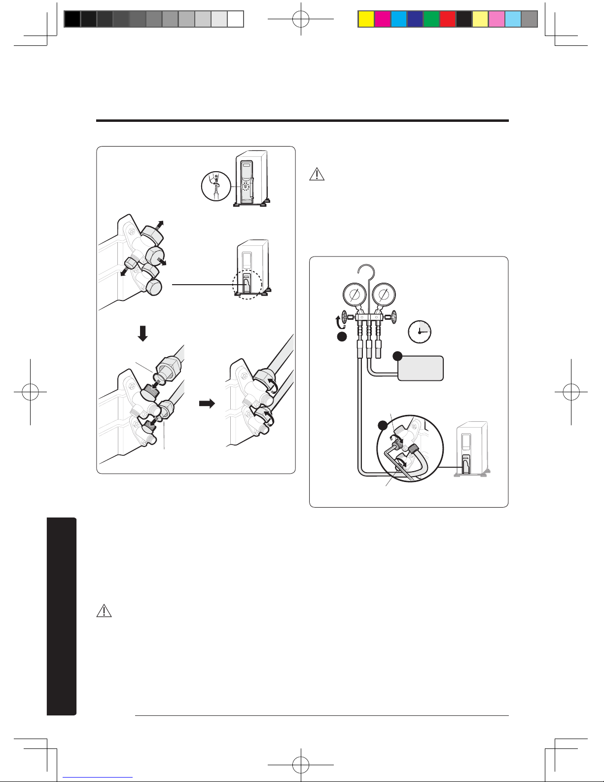
Step 3.3 Evacuating the air
The outdoor unit is loaded with sufficient R-410A
refrigerant. Do not vent R-410A into atmosphere: it is a
fluorinated greenhouse gas, covered by Kyoto Protocol,
with a Global Warming Potential (GWP) = 2088. You
should evacuate the air in the indoor unit and in the
pipe. If air remains in the refrigerant pipes, it affects the
compressor. It may cause reduction of cooling capacity and
malfunction. Use a vacuum pump.
CAUTION
• When installing, make sure there is no leakage. When
recovering the refrigerant, ground the compressor first
before removing the connection pipe. If the refrigerant
pipe is not properly connected and the compressor
works with the stop valve open, the pipe inhales the air
and it makes the pressure inside of the refrigerant cycle
abnormally high. It may cause explosion and injury.
1 Leave the system in the standby mode.
WARNING
• Do not turn on the system! This is necessary for
better vacuum operation (full OPEN position of
Electronic Expansion Valve).
2 Connect the charging hose of the low pressure side
of manifold gauge to a gas service port as seen in the
picture.
3
4
5
3 Open the valve of the low pressure side of manifold
gauge anticlockwise.
4 Evacuate the air in the connected pipes using the
vacuum pump for about 15 minutes.
• Make sure that pressure gauge shows -0.1 MPa
(-76 cmHg, 5 torr) after about 10 minutes. This
procedure is very important to avoid a gas leak.
• Close the valve of the low pressure side of
manifold gauge clockwise.
• Turn off the vacuum pump.
• Check for 2 minutes if there is any pressure
change.
• Remove the hose of the low pressure side of
manifold gauge.
5 Set a valve cork of liquid and gas service port to the
open position.
Control box
Remove the screw for the
control box cover
For connecting the
refrigerant pipes
Remove the gas and liquid
service port caps
Gas service port
<Low pressure>
Liquid service port
<High pressure>
Connect the gas and liquid
refrigerant pipes
(Backward flowing prevention)
Liquid service port <Low pressure>
Vacuum
Pump
Valve
15 minutes
Liquid service port <High pressure>
A3050_EU_Best model_IM_DB68-06152A-00_EN.indd 18 2016/4/20 14:10:24
Page 20
19English
Installation
Step 3.4 Adding refrigerant
If you use a pipe longer than the length specified in
the piping codes and standards, you must add 15g of
refrigerant R-410A for each extra metre. If you use a pipe
shorter than the length specified in the piping codes and
standards, the evacuating time is normal. Refer to the
Service Manual for further details.
CAUTION
• The remaining air in the Refrigeration cycle, which
contains moisture, may cause malfunction of the
compressor.
• Always contact the service centre or a professional
installation agency for product installation.
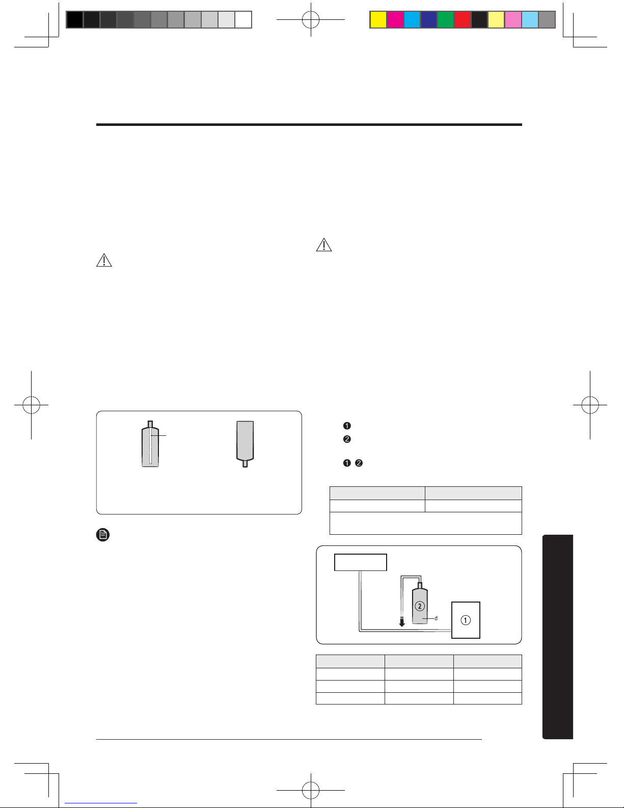
R-410A is a mixed type of refrigerant. It is necessary for
recharging under conditions of liquid. When recharging
refrigerant from the refrigerant cylinder to the equipment,
take the following instructions:
Before recharging, check whether the cylinder has
a siphon or not. There are two ways to recharge the
refrigerant:
NOTE
• If R-410A refrigerant is charged with gas, the
composition of the charged refrigerant changes and
the characteristics of the equipment vary.
• During the measuring operation of refrigerant quantity
added, use electronic scales. If cylinder doesn't have
siphon, upset it.
Step 3.5 Important information
regulation regarding the refrigerant
used
This product contains fluorinated greenhouse gases. Do
not vent gases into the atmosphere.
CAUTION
• Inform user if system contains 5 tCO2e or more of
fluorinated greenhouse gases. In this case, it has to be
checked for leakage at least once every 12 months,
according to regulation n°517/2014. This activity has
to be covered by qualified personnel only. In case
situation above (5 tCO2e or more of R-410A), installer
(or recognized person which has responsibility for
final check) has to provide a maintenance book, with
all the information recorded according to REGULATION
(EU) No 517/2014 OF THE EUROPEAN PARLIAMENT
AND OF THE COUNCIL of 16 April 2014 on fluorinated
greenhouse gases.
1 Please fill in the following with indelible ink on the
refrigerant charge label supplied with this product and
on this manual.
•
the factory refrigerant charge of the product,
•
the additional refrigerant amount charged in
the field and
•
+ the total refrigerant charge. on the
refrigerant charge label supplied with the product.
Refrigerant type GWP value
R-410A 2088
• GWP=Global Warming Potential
• Calculating tCO
2
e : kg x GWP / 1000
Unit Kg tCO2e
①, a
②, b
①+②, c
Indoor unit
Outdoor unit
Charge the refrigerant
standing the cylinder upright.
<Cylinder with siphon>
Charge the refrigerant turning
the cylinder upside down.
Siphon
<Cylinder without siphon>
A3050_EU_Best model_IM_DB68-06152A-00_EN.indd 19 2016/4/20 14:10:24
Page 21

20 English
Installation
NOTE
a Factory refrigerant charge of the product: see unit
name plate
b Additional refrigerant amount charged in the field
(Refer to the above information for the quantity of
refrigerant replenishment.)
C Total refrigerant charge
d Refrigerant cylinder and manifold for charging
CAUTION
• The filled-out label must be adhered in the proximity
of the product charging port (e.g. onto the inside of the
stop valve cover).
A3050_EU_Best model_IM_DB68-06152A-00_EN.indd 20 2016/4/20 14:10:24
Page 22

21English
Installation
Step 4.1 Performing the gas leak tests
1 Before inspecting the leakage, use a torque wrench
to close the cap for the stop valve. (Comply with a
tightening torque for each size of the diameter, and
tighten the cap firmly to prevent any leakage.)
2 Insert inert gas into the pipes connected to indoor and
outdoor units.
3 Test leakage on the connection parts of the indoor and
outdoor units with soap lather or liquid.
Step 4.2 Running the Smart Install
mode
If using a multi system, this function is not supported.
1 Make sure that the air conditioner is in the standby
status.
2 Hold down the
(Power), (Mode), and (SET)
buttons on the remote control simultaneously for 4
seconds.
3 Wait until Smart Install mode succeeds or fails. It takes
approximately 7 to 13 minutes.
• While Smart Install mode is proceeding:
Type
Display
LED Display
Indoor
unit
indicator
LED1
LED2
LED3
The progress
is displayed
as a number
between 0
and 99 on the
indoor unit
display.
The LEDs on the
indoor unit display
blink in sequence,
then all of them blink
simultaneously. These
operations repeat.
• When Smart Install mode succeeds: Smart Install
mode ends with ringing sound, and the air
conditioner is in standby status.
• When Smart Install mode fails: An error message
is displayed on the indoor unit display, and Smart
Install mode ends.
NOTE
• Smart Install mode can be operated only with the
supplied remote control.
• During the Smart install mode procedure, remote
control cannot be operated.
Installation Inspection
Outer diameter
(mm)
Tightening torque
Body cap
(N•m)
Charging port cap (N•m)
ø 6.35 20 to 25
10 to 12
ø 9.52 20 to 25
ø 12.70 25 to 30
ø 15.88 30 to 35
Over ø 19.05 35 to 40
(1N•m=10kgf•cm)
Tightening torque for body
cap (Refer to the table)
Charging core
Spindle
R-22: Thread of the screw - 7/16-2OUNF
R-410A: Thread of the screw -1/2-2OUNF
Tightening torque for charging port cap (Refer to the table)
Test parts for the
indoor unit
Test parts for the
indoor unit
A3050_EU_Best model_IM_DB68-06152A-00_EN.indd 21 2016/4/20 14:10:25
Page 23
22
English
Installation
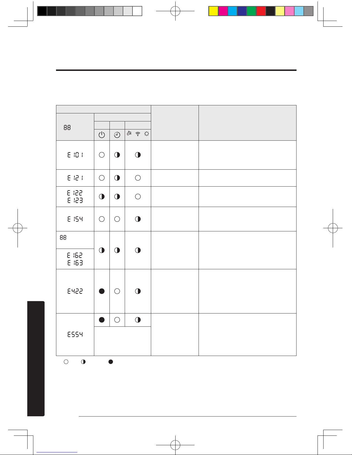
When error occurs, take necessary measures by referring to the following table. For more information on necessary
measures for errors, refer to the service manual.
Error indicator
Error Measures for the installer to take
Display
LED Display
LED 1 LED 2 LED 3
/ /
Communication
error between
indoor and outdoor
units
• Check the connection wire between the
indoor and outdoor units (whether the
power cable or communication cable is
crossed or not).
Error on indoor
temperature sensor
• Check the connection of the connector.
,
Error on indoor
heat exchanger
• Check the connection of the connector.
Error on indoor fan
motor
• Check the connection of the connector.
• Remove foreign substance. (Check for the
cause that restrains motor.)
display and
all LEDs blink.
EEPROM/Option
error
• Re-set options.
,
Refrigerant flow
blocking error
• Check if the stop valve is completely
open.
• Check if there is any blockage in the
refrigerant pipe which connects the
indoor and outdoor units.
• Check for refrigerant leak.
Lack of refrigerant
(for inverter models
only)
• Check if a sufficient amount of refrigerant
is additionally charged for the pipe
longer than specified in piping codes and
standards.
• Check for refrigerant leak between valve
and pipe connection.
This LED pattern
appears when an
error occurs on the
outdoor unit.
: Off, : Blinking, : On
A3050_EU_Best model_IM_DB68-06152A-00_EN.indd 22 2016/4/20 14:10:26
Page 24
23English
Installation
Step 4.3 Performing final check and
trial operation
1 Check the following:
• Strength of the installation site
• Tightness of pipe connection to detect gas leak
• Electric wiring connection
• Heat-resistant insulation of the pipe
• Drainage
• Grounding conductor connection
• Correct operation (Take the following steps.)
2 Press the
(Power) button on the remote control to
check the following:
• The indicator on the indoor unit lights up.
• The airflow blade opens and the fan gears up for
operation.
3 Press the
(Mode) button to select Cool or Heat
mode. Then take the following sub-steps:
• In Cool mode, use the Temperature button to set
the set temperature to 16 °C.
• In Heat mode, use the Temperature button to set
the set temperature to 30 °C.
• Check whether, approximately 3 to 5 minutes
later, the outdoor unit starts, and a cool or warm
air blows out.
• After 12 minutes of stationary condition, check
the indoor unit air treatment.
4 Press the
(Air swing) button to check whether the
airflow blades work properly.
5 Press the
(Power) button to stop the trial operation.
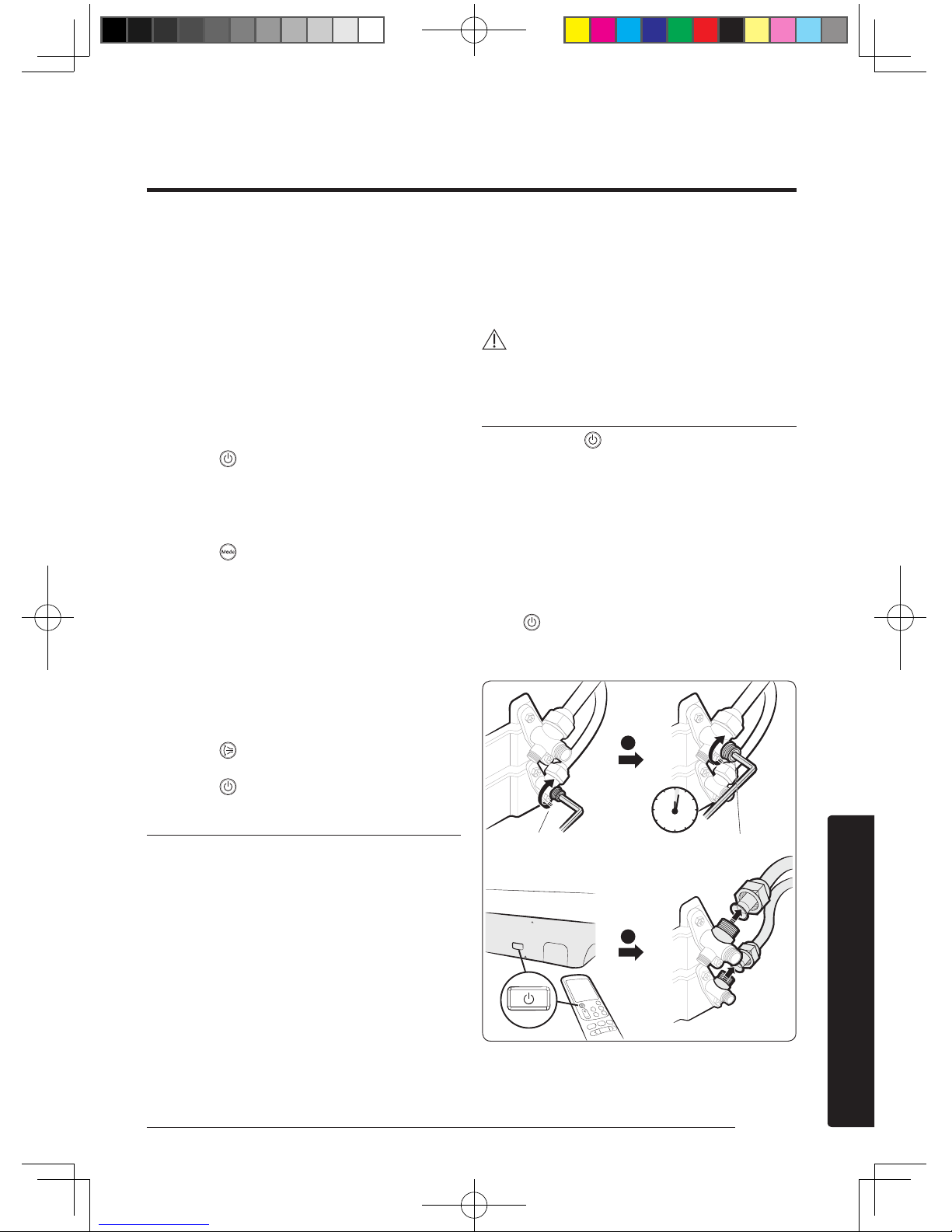
Pumping down refrigerant
Pump-down is an operation intended to collect all the
system refrigerant in the outdoor unit. This operation must
be carried out before disconnecting the refrigerant tubing
in order to avoid refrigerant loss to the atmosphere.
1 Shut off the liquid valve with the Allen wrench.
2 Turn on the air conditioner in cooling with fan
operating at high velocity. (Compressor will
immediately start, provided 3 minutes have elapsed
since the last stop.)
3 After 2 minutes of operation, shut the suction valve
with the same wrench.
4 Turn off the air conditioner and switch mains supply
off.
5 Disconnect tubing. After disconnection, protect valves
and tubing ends from dust.
CAUTION
• Compressor damage may occur if the compressor is
run at a negative suction pressure.
Pumping down for removing the product
1 Hold down the (Power) button on the indoor unit
for 5 seconds. Beep sounds immediately to indicate
that the product is ready for pump down procedure.
2 Let the compressor run for more than 5 minutes.
3 Release the valve caps on High and Low pressure side.
4 Use L-wrench to close the valve on the high pressure
side.
5 After approximately 1 minute, close the valve on the
low pressure side.
6 Stop operation of the air conditioner by pressing
the
(Power) button on the indoor unit or remote
control.
7 Disconnect the pipes.
1
2
Liquid service port
<High pressure>
Gas service port
<Low pressure>
Off
1 minute
A3050_EU_Best model_IM_DB68-06152A-00_EN.indd 23 2016/4/20 14:10:27
Page 25
24 English
Installation
Only for multi system
(Wried remote controller, central remote controller etc.)
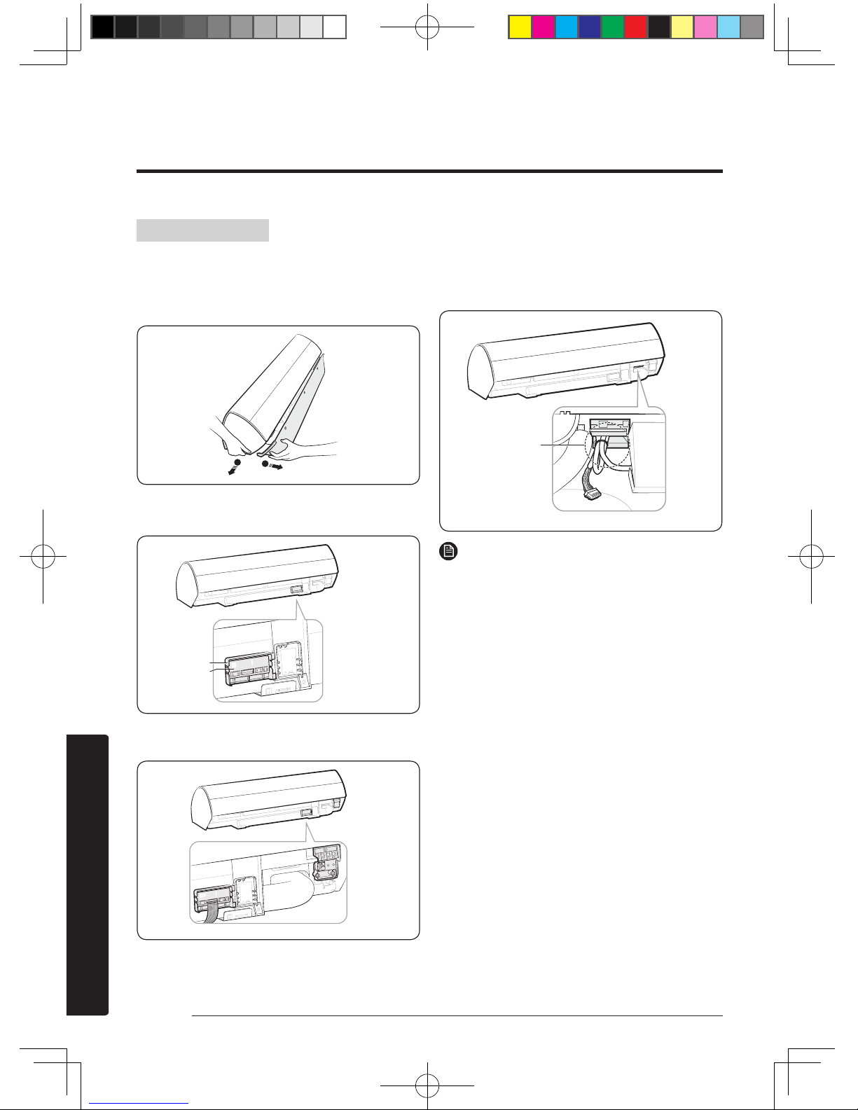
1 Turn the power off and take off the cover panel of the
indoor unit.
1
2
2 Attach the Sub PCB to the Case Sub PCB.
3 Assemble the Case Sub PCB to the indoor unit.
4 Find the PCB wire, and connect the wire to the Sub PCB
as seen in the picture.
5 Connect the wire(remote controller, central remote
controller etc) to the Sub PCB.
6 Assemble the Cover PCB and the front panel.
If the Sub PCB is not installed, arrange the wire for
multi system (connection) as shown in the illustration.
NOTE
• The Sub PCB is attached to be controlled by the wired
remote controller and central controller.
Sub PCB installation(optional)
Wire for multi
system connection
Sub PCB
Case Sub PCB
A3050_EU_Best model_IM_DB68-06152A-00_EN.indd 24 2016/4/20 14:10:28
 Loading...