

Samsung AR18HSFNBWKXEU, AR18HSFSAWKNEU, AR24HSFNBWKXEU, AR24HSFSAWKNEU, AR24HSFSAWKXEU Service Manual
...
AIR CONDITIONER CONTENTS
SPLIT-TYPE AIR CONDITIONER
snoituacerP.1
3. Alignment and Adjustments
4. Disassembly and Reassembly
5. Disassembly WIFI
6. Electrical Parts List
7. Wiring Diagram
8. PCB Diagram
9. Operating Instructions
10. Troubleshooting
11. Block Diagram
12. Reference Sheet
Refer to the service manual in the GSPN (see the rear cover) for the More information
INDOOR OUTDOOR INDOOR OUTDOOR
MODEL NAME
AR18HSFNBWKNEU AR18HSFNBWKXEU BASIC MODEL AR18HSFSAWKNEU AR18HSFSAWKXEU
AR24HSFNBWKNEU AR24HSFNBWKXEU AR24HSFSAWKNEU AR24HSFSAWKXEU
AR18HSSDBWKNEU AR18HSSDBWKXEU AR24HSFSAWKNEU AR24HSFSAWKXEU
AR24HSSDBWKNEU AR24HSSDBWKXEU AR24HSFSAWKNEU AR24HSFSAWKXEU
AR24HSFSRWKNER AR24HSFSRWKXER AR24HSFSAWKNEU AR24HSFSAWKXE U
AR24HSFNRWKNER AR24HSFNRWKXER AR24HSFSAWKNEU AR24HSFSAWKXEU
AR18HSFSRWKNER AR18HSFSRW
KXER AR18HSFSAWKNEU AR18HSFSAWKXEU
AR18HSFNRWKNER AR18HSFNRWKXER AR18HSFSAWKNEU AR18HSFSAWKXEU

Samsung Electronics 1
Contents
1. Precautions
·············································································································
1-1
1-1 Installing the air conditioner·························································································································· 1-1
1-2 Power supply and circuit breaker················································································································· 1-1
1-3 During operation ················································································································································ 1-1
1-4 Disposing of the unit········································································································································· 1-2
1-5 Others ······································································································································································ 1-2
2. Product Specifications······························································································· 2-1
2-1 The Feature of Product ····································································································································· 2-1
2-2 Product Specifications ······································································································································ 2-2
2-3 The Comparative Specifications of Product····························································································· 2-6
2-4 Accessory and Option Specifications ········································································································· 2-8
3. Alignment and Adjustments········································································ 3-1
3-1 Test Mode······························································································································································· 3-1
3-2 Outdoor LED Display Error and Check Method ····················································································· 3-2
3-3 Setting Option Setup Method······················································································································· 3-5
3-4 Setting Option Setup Method······················································································································· 3-9
4. Disassembly and Reassembly ······································································ 4-1
4-1. Indoor Unit···························································································································································· 4-2
4-2. Outdoor Unit························································································································································ 4-12
5. Disassembly WIFI··························································································· 5-1
5-1 WIFI Case································································································································································· 5-1
5-2 ASSY CONTROL IN ·············································································································································· 5-2
5-3 Assy Control Out ················································································································································ 5-4
6. Electrical Parts List ························································································ 6-1
6-1 INDOOR MAIN PCB (DB92-02873A)············································································································· 6-1
6-4 OUTDOOR MAIN PBA(DB92-02866A) - 12K/18K ·····················································································
6-7 OUTDOOR MAIN PBA(DB90-02877A) - 24K······························································································ 6-11
6-8 ASSY WIFI PCB······················································································································································ 6-20
7. Wiring Diagram······························································································ 7-1
7-1 Indoor Unit····························································································································································· 7-1
7-2 Outdoor Unit ························································································································································ 7-2
7-3 ASSY WIFI KIT························································································································································ 7-3
6-5

2 Samsung Electronics
Contents
8. PCB Diagram ·································································································· 8-1
8-1 Indoor Unit····························································································································································· 8-1
8-2 Outdoor PCB ························································································································································ 8-2
8-3 Wire connecting the indoor unit terminal blocks················································································· 8-8
9. Operating Instructions·················································································· 9-1
9-1 Name of Each Part ·············································································································································· 9-1
9-2 Wireless Remote Control-Buttons and Display······················································································· 9-2
10. Troubleshooting ··························································································10-1
10-1 Items to be checked first······························································································································· 10-1
10-2 Communication Error····································································································································· 10-2
10-3 PCB Inspection Method································································································································· 10-37
10-4 ASSY WIFI KIT Inspection Method············································································································· 10-39
11. Block Diagram ·····························································································11-1
11-1 Indoor unit ·························································································································································· 11-1
11-2 Outdoor unit······················································································································································· 11-2
12. Reference Sheet··························································································· 12-1
12-1 Low Refrigerant Pressure Distribution····································································································· 12-1
12-2 Pressure & Capacity mark······························································································································ 12-1
12-3 Q & A for Non-trouble····································································································································· 12-2
12-4 Cleaning /Filter Change································································································································· 12-5
12-5 Installation··························································································································································· 12-6
12-6 Installation Diagram of Indoor Unit and Outdoor Unit···································································· 12-7
Samsung Electronics 1-1
1. Precautions
1-1 Installing the air conditioner
O Uses should not install the air conditioner by themselves.
Ask the dealer or authorized company to install the air conditioner except window-type air conditioner in U.S.A and Canada.
O If you don't install the air conditioner properly, it may cause a fire, a
water leakage or an electric shock.
O You must install the air conditioner according to the national wiring regulations and safety regulations.
O
Install the indoor unit higher than 2.5m from the floor to avoid the injury caused by the oper ation of the fan.
(except the window-type air conditioner)
O The manufacturer is not responsible for any accidents or injury caused by an incorrect installation.
O When installing the built-in type air conditioner, keep all electric cables such as the power cable and the connection cord in
pipes, ducts, or cable channel
s to protect them from the danger of impact or any other incidents.
1-2 Power supply and circuit breaker
O If the power cord of the air conditioner is damaged, it must be replaced by the manufacturer or a qualified person in order
to avoid a hazard.
O The air conditioner must be plugged into an independent circuit if applicable or connect the pow
er cable to the auxiliary circuit
breaker .
An all pole disconnection form the power supply must be incorporated in the fixed wiring with a con tact opening of>3mm.
O Do not extend an electric cord to the air conditioner .
O The air conditioner
must be plugged in after you complete the installation.
1-3 During operation
O Do not repair the air conditioner at your discretion.
It is recommended to contact a service center directly.
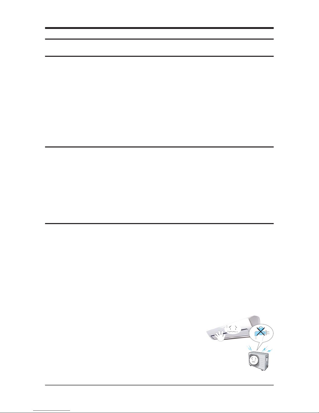
O Never spill any kind of liquid on the air conditioner.
If this happens, turn off the air conditioner and contact an authorized service center.
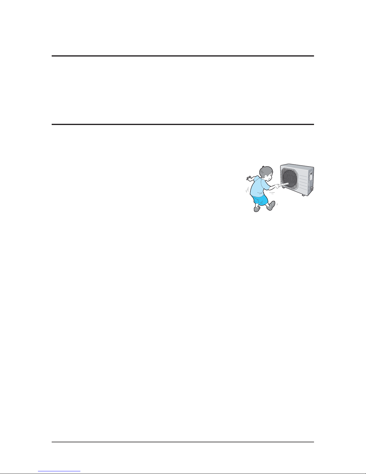
O Do not insert anything betw
een the airflow blades to prevent damage of the inner fan and consequent injury.
Keep children away from the air conditioner.
O Do not place any obstacles in front of the air conditioner.
O Do not spray any kind of liquid into the indoor unit.
If this happens, turn off the air conditioner and contact a service center.
O Make sure that the air conditioner is well ventilated at all times.
Do not place a cloth or other materials over it.
O Remove the batteries if you don't use the remote control
for a long time. (If applicable)
O Use the remote control within 7 meters from the indoor unit. (If applicable)
1-2 Samsung Electronics
1-4 Disposing of the unit
O Before the throwing out the air conditioner, remove the batteries from the remote control.
O When you dispose of the air conditioner, consult your dealer . If pipes are removed incorr ectly, refrigerant may blow out
and cause air pollution. When it contacts with your skin,
it can cause skin injury.
O The package of the air conditioner should be recycled or disposed of properly for environmental reasons.
1-5 Others
O Never store or load the air conditioner upside down or sideways to prevent the damage to the compressor.
O Young children or infirm persons should be always supervised when they use the air conditioner.
O Max current is measured according to IEC standard for safety.
O Current is
measured according to ISO standard for energy efficiency.

Samsung Electronics 2-1
2. Product Specifications
2-1 The Feature of Product
䒲#
2 step cooling
- Get cool quickly and keep cool comfortably without shivering
䒲#
Single user mode
- No worrying about the electricity bill, even using it when you're alone.
䒲#
Crystal gloss design
- Uniquely stylish and innovative design to enhance your life and home
䒲#
Smart Wi-Fi
- Control air conditioner anytime and anywhere
䒲#
Smart Installation
- Get the condence that it's perfectly installed
䒲#
Smart Installation
- Get the condence that it's perfectly installed
䒲#
Smart Check
- Don’t worry about the trouble-shooting in your home
䒲#
Triple Protector Plus
- Use longer without damage in unsuitable conditions
䒲#
Easy Installation
- Secure the easy Installation of Indoor unit and pipe connection
䒲#
Easy Filter
- Quick and easy to clean lter saves time and eort
2-2 Samsung Electronics Samsung Electronics 2-3
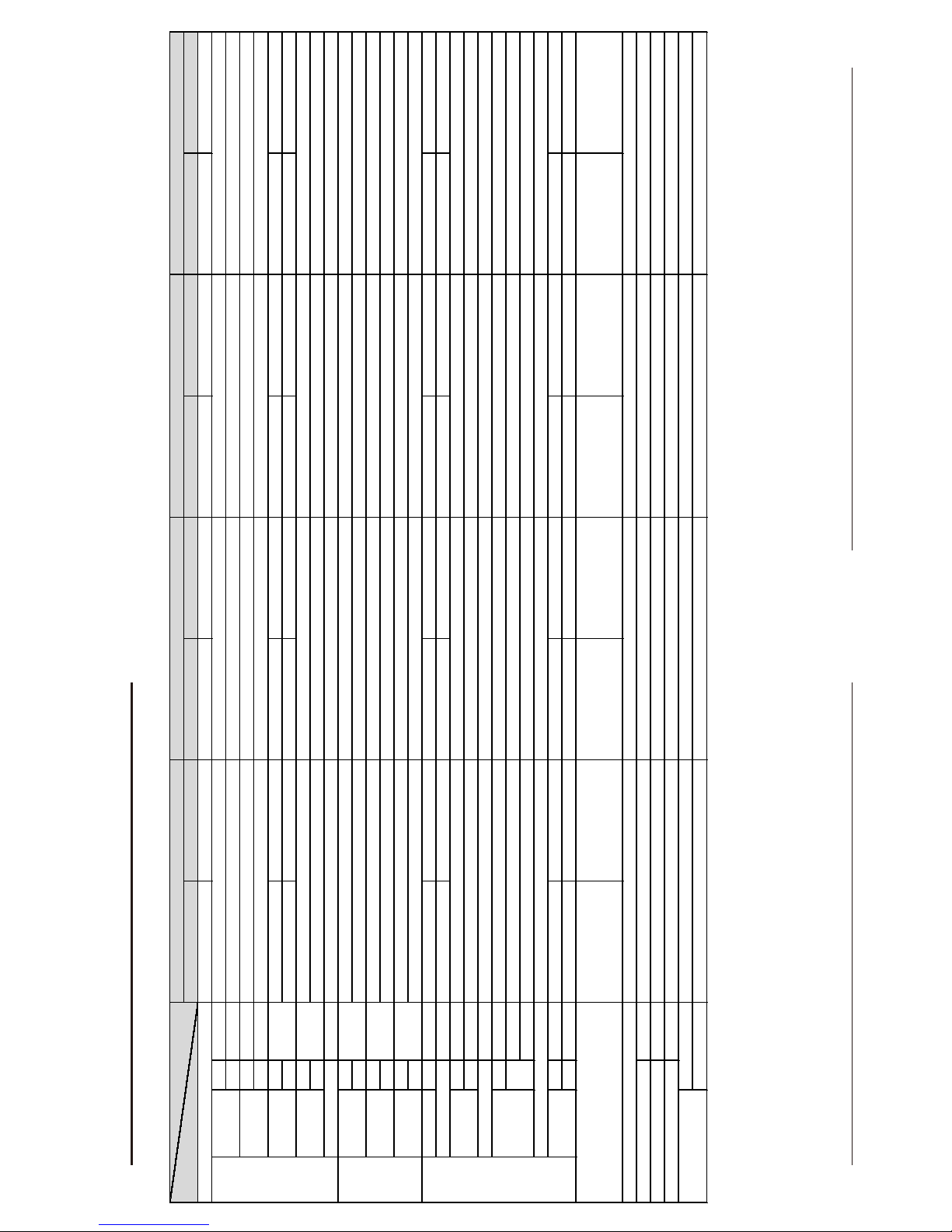
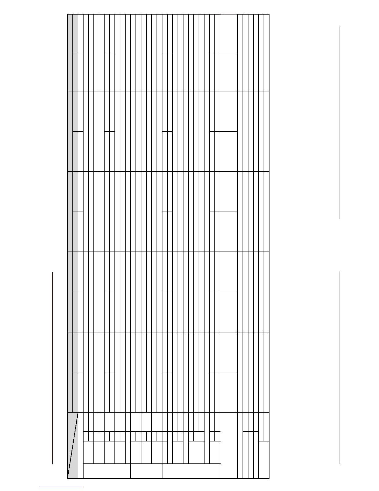
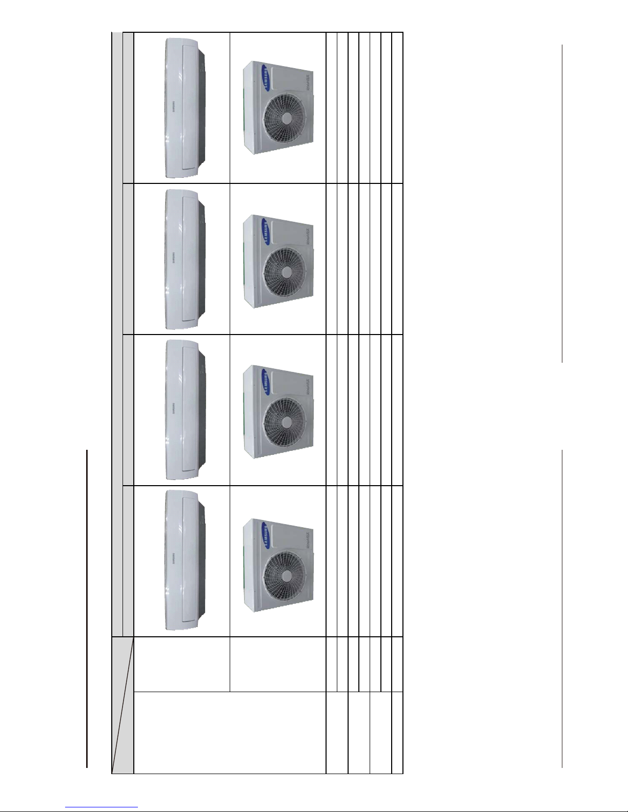
2-2 Product Specifications
Indoor Unit Outoor Unit Indoor Unit Outoor Unit Indoor Unit Outoor Unit Indoor Unit Outoor Unit
Wall-mounted Wall-mounted Wall-mounted Wall-mounted Wall-mounted Wall-mounted Wall-mounted Wall-mounted
Cooling KW
Heating (Low/Std/Max)
Cooling Hz
Heating (Low/Std/Max)
⭿☚
51 62 46 57 51 60 51 60
⭿┮䘖
60 67 58 65 62 67 - -
Cooling
Heating
ph-V-Hz
Cooling
Heating
Cooling
Heating
Cooling
Heating
Gross Dimension
W*D*H mm 1123*354*384 1023*904*413 1123*354*384 1023*904*413 1123*354*384 1023*904*413 1123*354*384 1023*904*413
kg 14. 06 52.4 14.1 52.4 14.06 52.4 14.06 52.4
Liquid mm
Gas mm
L*D
Type
Type
Rated Output(W)
Type CROSS-FLOW PROPELLER CROSS-FLOW PROPELLER CROSS-FLOW PROPELLER CROSS-FLOW PROPELLER
motor Type BLDC BLDC BLDC BLDC BLDC BLDC BLDC BLDC
2ROW x 10STEP x L840+
2ROW x 6STEP x L840
1ROW x 8STEP x L840+
1ROW x 4STEP x L840
L = 880mm / 7-9-11-13-14-17 (6turn)
2ROW x 10STEP x L840+
2ROW x6STEPxL840
1ROW x 8STEP x L840+
1ROW x4STEPxL840
L = 880mm / 7-9-11-13-14-17 (6turn)
2ROW x 10STEP x L840+
2ROW x 6STEP x L840
1ROW x 8STEP x L840+
1ROW x4STEPxL840
L = 880mm / 7-9-11-13-14-17 (6turn)
2ROW x 10STEP x L840+
2ROW x 6STEP x L840
1ROW x 8STEP x L840+
1ROW x 4STEP x L840
L = 880mm / 7-9-11-13-14-17 (6turn)
cc
g
NONE
-10
ć
~46
ć
-15
ć
~24
ć
HERMETIC
-
R410
1500
6.35 (1/4 inch)
15.88 (5/8 inch)
550±20
UG4T200FUAE4
3.62
1phase, 220-240V~, 50Hz
0.49/2.06/2.8
0.43/2.21/3.65
2.6/9.0/12.5
2.3/10.8/16.5
-10
ć
~46
ć
-15
ć
~24
ć
AR24HSFSRWK/ER
2.2/6.8/8.0
1.9/8.0/10.0
15/66/88
15/74/100
3.3
UG4T200FUAE4
HERMETIC
-
R410
-
2.3/10.8/16.5
75/90/95
75/90/95
6.35 (1/4 inch)
15.88 (5/8 inch)
550±20
3.4
3.62
75/90/95
75/90/95
0.49/2.0/2.8
0.43/2.21/3.65
2.6/8.9/12.5
HERMETIC
-
-
1150
NONE
1.8/6.0/9.7
1.5/6.8/10.5
75/90/95
1500
NONE
R410
75/90/95
AR24HSSDBWK/EU
2.2/6.8/8.0
1.9/8.0/10.0
15/66/88
15/74/100
AR18HSSDBWK/EU
3.9
4.11
1phase, 220-240V~, 50Hz 1phase, 220-240V~, 50Hz
Heat Exchanger
Refrigerant Control Unit
Operation condition range
Cooling
Proterction Device(OLP)
Refrigerant to Change(R410A)
R410
1500
NONE
-10
ć
~46
ć
-10
ć
~46
ć
Heating
-15
ć
~24
ć
-15
ć
~24
ć
Freezer Oil Capacity - -
Motor
6.35 (1/4 inch) 6.35 (1/4 inch)
15.88 (5/8 inch) 12.7 (1/2 inch)
Size
Weight(Net)
Refrigerant Pipe
Drain Hose
Blower
Oil Type
550±20 550±20
Compressor
UG4T200FUAE4 UG4T200FUAE4
-
-
HERMETIC
0.49/2.06/3.0 0.38/1.28/2.2
0.43/2.35/3.65 0.3/1.46/2.1
2.6/9.0/13.0
2.3/11.0/16.5
75/90/95
75/90/95
Pow
Power Consumtion
KW
(Low/Std/Max)
Operating Current
A
(Low/Std/Max)
Power
Noise
dB
(H/L)
Energy Efficiency
Ratio
W/W
(Std)
Power Factor
%
(Low/Std/Max)
MODEL
ITEM
15/66/88 15/44/73
15/74/100 15/54/75
2.2/6.8/8.0 1.6/5.0/6.0
1.9/8.0/10.0 1.2/6.0/8.2
Type
Performance
Capacity
Running Frequency
AR24HSFNBWK/EU
3.3
3.4
1phase, 220-240V~, 50Hz
2-2 Samsung Electronics Samsung Electronics 2-3
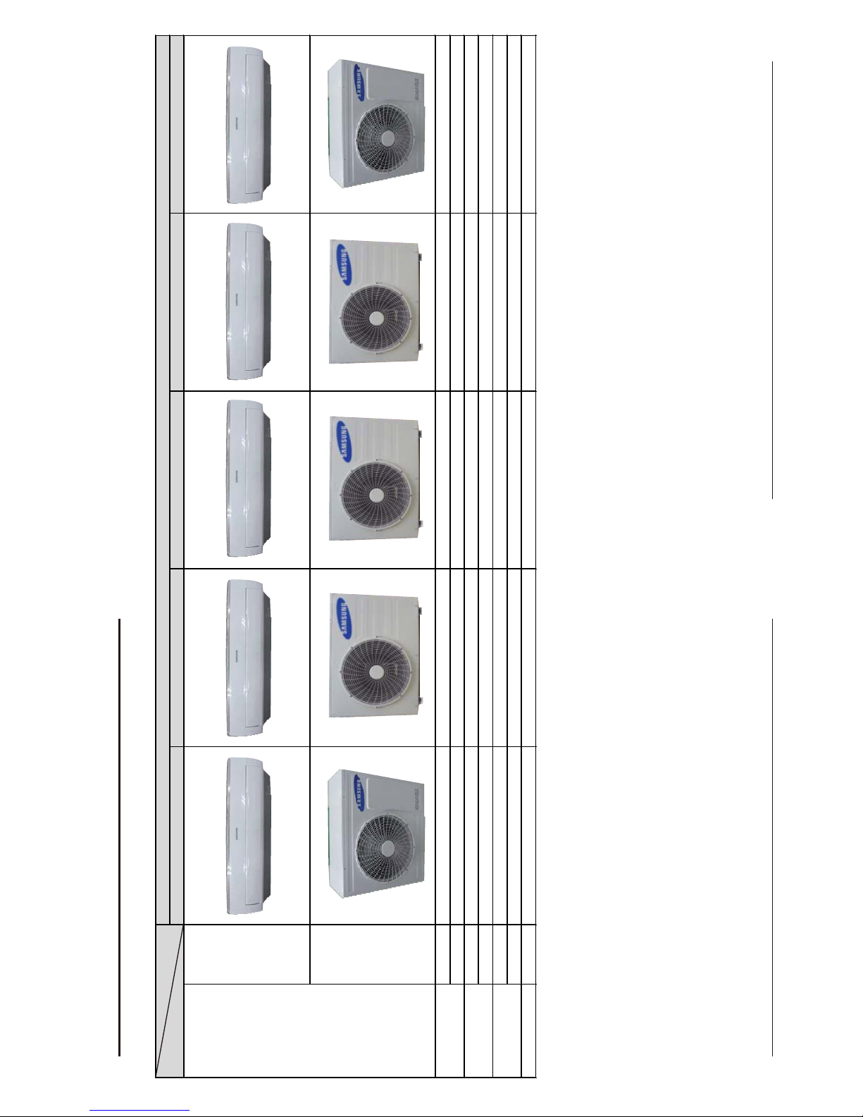
2-2 Product Specifications
Indoor Unit Outoor Unit Indoor Unit Outoor Unit Indoor Unit Outoor Unit Indoor Unit Outoor Unit Indoor Unit Outoor Unit
Wall-mounted Wall-mounted Wall-mounted Wall-mounted Wall-m ounted W all-mounted W all-mounted Wall-mounted Wall-mounted Wall-mounted
Cooling KW
Heating (Low/Std/Max)
Cooling Hz
Heating (Low/Std/Max)
⭿☚
51 60 46 57 46 58 51 60
⭿┮䘖
---- 57 65 - -
Cooling
Heating
ph-V-Hz
Cooling
Heating
Cooling
Heating
Cooling
Heating
Gross Dimension
W*D*H mm 1123*354*384 1023*904*413 1123*354*384 1023*760*413 1123*354*384 1023*760*413 1123*354*384 1023*760*413 1123*354*384 1023*904*413
kg 14.06 52.4 13.2 43.5 13.2 43.5 13.2 43.5 14.06 52.4
Liquid mm
Gas mm
L*D
Type
Type
Rated Output(W)
Type CROSS-FLOW PROPELLER CROSS-FLOW PROPELLER CROSS-FLOW PROPELLER CROSS-FLOW PROPELLER CROSS-FLOW PROPELLER
motor Type BLDC BLDC BLDC BLDC BLDC BLDC BLDC BLDC BLDC BLDC
2ROW x 10STEP x L840+
2ROW x 6STEP x L840
1ROW x 8STEP x L840+
1ROW x 4STEP x L840
L = 880mm / 7-9-11-13-14-17 (6turn)
2ROW x 10STEP x L840+
2ROW x 5(6)STEP x L840
L = 880mm
2ROW x 10STEP x L840+
2ROW x 5(6)STEP x L840
L = 880mm
2ROW x 10STEP x L840+
2ROW x 5(6)STEP x L840
L = 880mm
2ROW x 10STEP x L840+
2ROW x 6STEP x L840
1ROW x 8STEP x L840+
1ROW x 4STEP x L840
L = 880mm / 7-9-11-13-14-17 (6turn)
cc
g
-10
ć
~46
ć
-15
ć
~24
ć
0.49/2.12/2.8
0.43/2.16/3.65
2.2/6.8/8
1.9/7.8/10
15/66/88
15/74/100
550±20
UG4T200FUAE4
HERMETIC
-
R410
1500
NONE
3.3
3.62
1phase, 220-240V~, 50Hz
2.6/10.5/12.5
2.3/10.7/16.5
75/90/95
75/90/95
6.35 (1/4 inch)
15.88 (5/8 inch)
AR24FSFNAWKNFA
1.6/5.0/6.0
1.2/6.0/8.2
15/62/72
15/73/100
46
57
1.6/5.0/6.0
1.2/6.0/8.2
15/62/72
15/73/100
MODEL
ITEM
AR18HSFSRWK/ER AR18HSFNRWK/ER
Type
Performance
Capacity
1.6/5.0/6.0
1.2/6.0/8.2
Running Frequency
15/62/72
Noise
dB
(H/L)
Energy Efficiency
Ratio
W/W
(Std)
3.45 3.45
3.45
3.61 3.61
3.61
Power 1phase, 220-240V~, 50Hz
Pow
Power Consumtion
KW
(Low/Std/Max)
0.3/1.45/1.9
0.26/1.66/2.4
Operating Current
A
(Low/Std/Max)
1.7/6.8/8.5
1.6/7.8/10.8 1.6/7.8/10.8
1.6/7.8/10.8
Power Factor
%
(Low/Std/Max)
75/90/95 75/90/95
75/90/95
75/90/95 75/90/95
75/90/95
Size
Weight(Net)
Refrigerant Pipe
6.35 (1/4 inch)
12.7 (1/2 inch)
Drain Hose 550±20
Compressor
UG4T150LNBEQ (44TBR150)
HERMETIC
-
R410
Proterction Device(OLP) NONE
Operation condition range
Cooling
-10
ć
~46
ć
Heating
-15
ć
~24
ć
Freezer Oil Capacity -
Refrigerant to Change(R410A) 1150
Oil Type -
Blower
Heat Exchanger
Refrigerant Control Unit R410
Motor
HERMETIC
-
AR24HSFNRWK/ER
2.2/6.8/8.0
1.9/8.0/10.0
15/66/88
15/74/100
3.3
3.62
15/73/100
R410
880
NONE
-10
ć
~46
ć
-15
ć
~24
ć
1phase, 220-240V~, 50Hz
0.3/1.45/1.9
1500
NONE
-10
ć
~46
ć
-15
ć
~24
ć
1phase, 220-240V~, 50Hz
0.49/2.06/2.8
0.43/2.21/3.65
2.6/9.0/12.5
2.3/10.8/16.5
75/90/95
75/90/95
6.35 (1/4 inch)
15.88 (5/8 inch)
550±20
UG4T200FUAE4
AR18HSFNBWK/EU
1phase, 220-240V~, 50Hz
0.3/1.45/1.9
0.26/1.66/2.4
6.35 (1/4 inch)
12.7 (1/2 inch)
550±20
UG4T150LNBEQ (44TBR150)
-
UG4T150LNBEQ (44TBR150)
HERMETIC
HERMETIC
-
-
1.7/6.8/8.5
1.7/6.8/8.5
-10
ć
~46
ć
-15
ć
~24
ć
0.26/1.66/2.4
6.35 (1/4 inch)
12.7 (1/2 inch)
550±20
R410
1150
NONE
2-6 Samsung Electronics Samsung Electronics 2-7
2-3 The Comparative Specifications of Product
AR24HSFNBWK/EU AR18HSSDBWK/EU AR24HSSDBWK/EU AR24HSFSRWK/ER
Indoor Unit
Outdoor Unit
Indoor Unit 14.06 14.06 14.06 14.06
Outdoor Unit 52.4 52.4 52.4 52.4
Indoor Unit 1123*354*384 1123*354*384 1123*354*384 1123*354*384
Outdoor Unit 1023*904*413 1023*904*413 1023*904*413 1023*904*413
Indoor Unit 51/60 46/58 51/62 51
Outdoor Unit 62/67 57/65 60/67 60
Air Purif
y
in
g
S
y
stem Filter FULL HDFILTER FULL HDFILTER FULL HDFILTER FULL HDFILTER
Outer Dimension
Noise
MODEL
ITEM
Net Weight
Design
Develop Model
2-6 Samsung Electronics Samsung Electronics 2-7
2-3 The Comparative Specifications of Product
AR24HSFNRWK/ER AR18HSFSRWK/ER AR18HSFNRWK/ER AR18HSFNBWK/EU AR24FSFNAWKNFA
Design Indoor Unit
Outdoor Unit
Indoor Unit 14.06 13.2 13.2 13.2 14.06
Outdoor Unit 52.4 43.5 43.5 43.5 52.36
Indoor Unit 1123*354*384 1123*354*384 1123*354*384 1123*354*384 1123*354*384
Outdoor Unit 1023*904*413 1023*760*413 1023*760*413 1023*760*413 1023*904*413
Indoor Unit 51 46 46 46(Sound Pressure)/58(Sound Power) 51
Outdoor Unit 60 57 57 57(Sound Pressure)/65
(Sound Power) 60
Air Purif
y
in
g
S
y
stem Filter FULL HDFILTER FULL HDFILTER FULL HDFILTER FULL HDFILTER FULL HDFILTER
Net Weight
Develop Model
Outer Dimension
Noise
MODEL
ITEM
2-8 Samsung Electronics
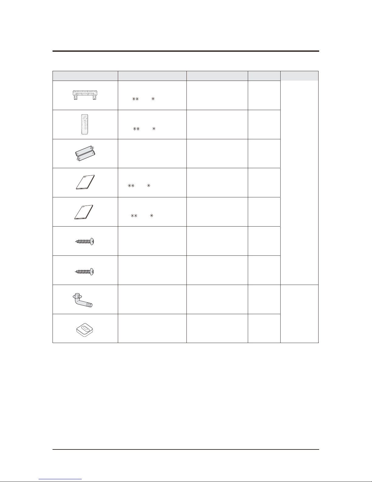
2-4 Accessory and Option Specifications
krameRYT'Q.oN-edoCsnoitpircseDmetI
Indoor unit case
Installation Plate
DB90-07731A
1
Remote controller
1
Batteries for Remote controller
4301-000121
2
Wi-Fi Manual
1
M4x10 Tapped Screws
DB97-23032A
2
M4 x 16 Tapped Screws
DB97-11984A
2
Drain Plug
DB67-20011A
1
Outdoor unit case
Rubber Leg
DB73-20134A
4
18(24) (05 frame)
1
18(24) (05 frame)
DB93-14195A
Manual Users Manual install
DB68-04211A
DB68-04212A
18(24) (05 frame)
/
DB68-04215A
18(24) (05 frame)
Samsung Electronics 3-1
3. Alignment and Adjustments
3-1 Test Mode
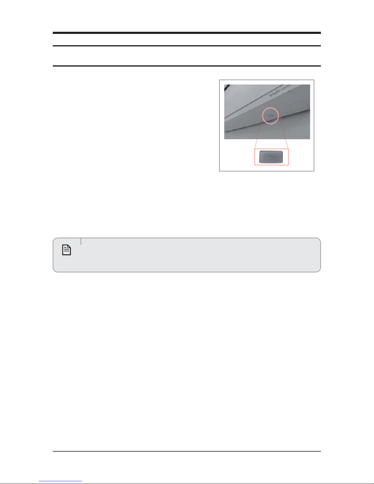
Q How to Approach Test Mode
You can approach the test mode by pressing the on/off switch of
indoor unit for 5 seconds.
Q Test mode operation option
After installing the air conditioner, check whether each subordinate is normally operated or not by operating the test mode.
●
When an Error occurs, display the Error Mode.
●
Operation Mode : Cool mode. operate the cool mode by operating the compressor by force without the compressor ON/OFF
according to the set temperature/indoor temperature. (Do not follow the antifreeze control)
●
Up-down louver : Up-down swing mode
●
Indoor Fan : Turbo
●
Because the teat mode operate the cool mode by force not related to the set temperature / indoor
temperature, check whether each subordinate is operated normally or not after completing installation
and must turn off the power of the air conditioner.
Note
3-2 Samsung Electronics
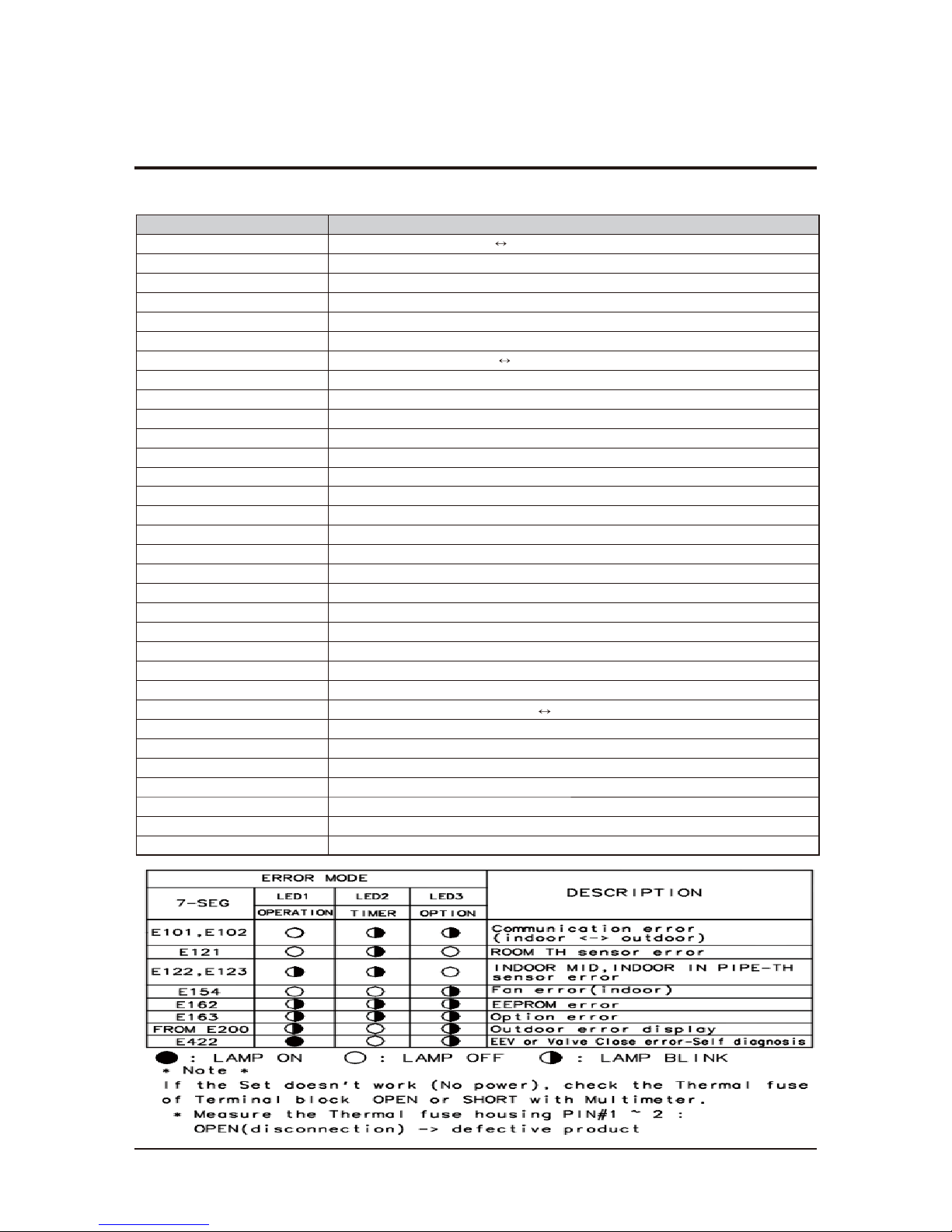
3-2 Display Error and Check Method
3-2-1 Indoor Display Error and Check Method
NOITPIRCSEDEDOMRORRE
E101 / E102
Communication Error (Indoor Outdoor)
E121
ROOM TH sensor error
E122
INDOOR MID, INDOOR IN PIPE-TH sensor error
E154
Fan Error (Indoor)
E162
EEPROM Error (Indoor)
E163
Option Error
E203
Time out Comm. (Inv Micom
Main Micom)
E221
OUT-TH(Outdoor Temperature) Sensor Error
E231
CON-TH(Cond Temperature) Sensor Error
E251 DIS-TH(Discharge Temperature) Sensor Error
E416 DIS-TH(Discharge Temperature) Over Error
E422 EEV or Valve Close error-Self diagnosis
E440 Prohibit Operation Condition Error (Heating)
E441 Prohibit Operation Condition Error (Cooling)
E458 Fan Error(Outdoor)
E461 Comp Starting Error
E462 AC Input I_Limit Trip Error
E464 IPM Over Current(O.C) Error
E465 Comp V_limit/I_limit Error
E466 DC-Link Voltage Under/Over Error
E467 Comp Wire Missing Error
E468 Current Sensor Error
E469 DC-Link Voltage Sensor Error
E470 EEPROM Data Error (no data)
E471
EEPROM Data Error (Main Micom
Inv Micom)
E474 Heatsink Sensor Error
E483 Over Voltage Protection Error
E484 PFC Over Load Error
E485 Input Current Sensor Error
E488 AC Input Voltage Sensor Error
E500 Heatsink Over Temperature Error
E554 Gas Leak Error
Samsung Electronics 3-3
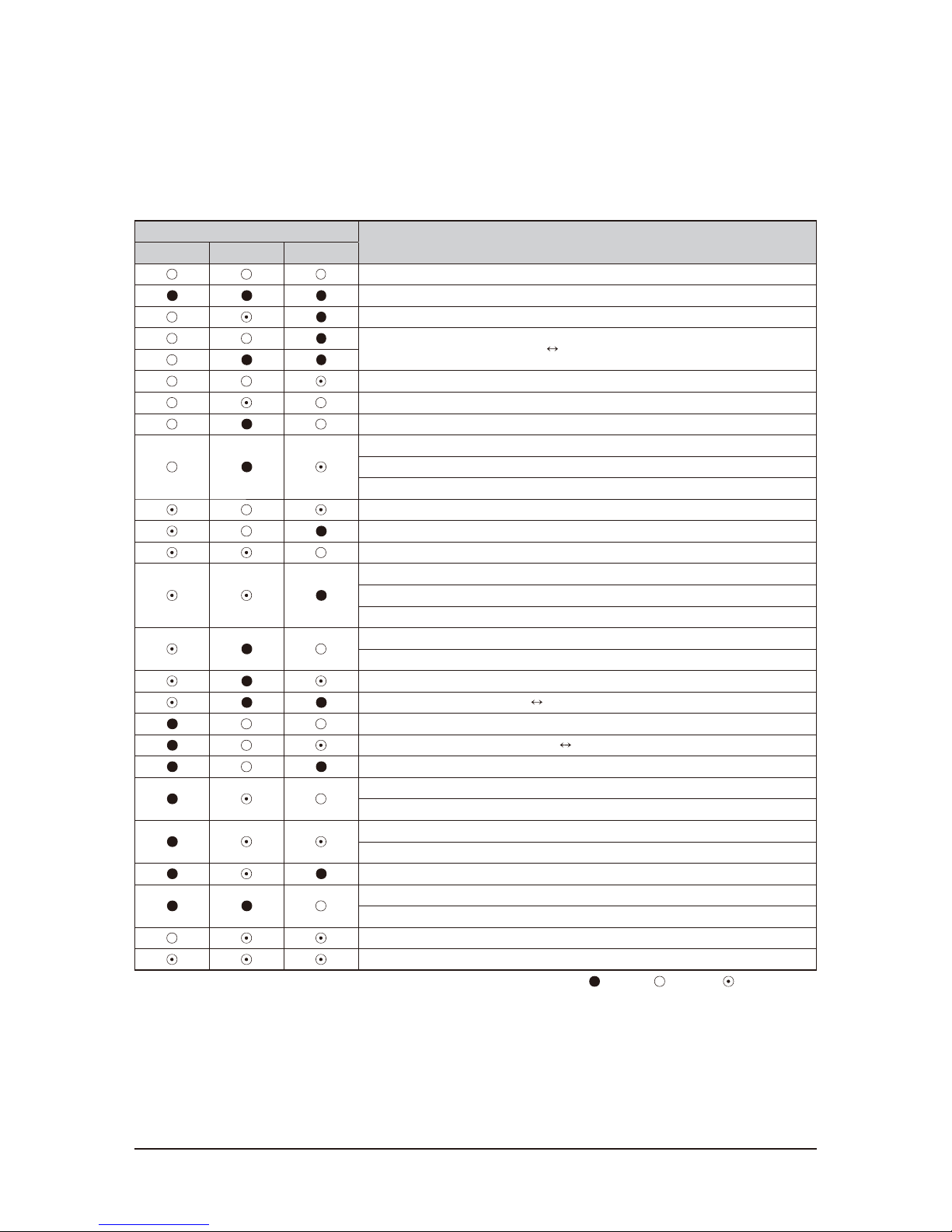
Outdoor LED Display Error and Check Method (12K/18K/24K)
LED PATTERN
DESCRIPTION
YEL GRN RED
Power off/VDD NG
Power ON reset(1sec)
Normal Operation
Abnormal Communication (Indoor Outdoor)
IPM Over Current(O.C) Error
Comp Starting Error
EEPROM Data Error (no data)
DC-Link Voltage Under/Over Error
PFC Over Load Error
Over Voltage Protection Error
OUT-TH(Outdoor Temperature) Sensor Error
DIS-TH(Discharge Temperature) Over Error
DIS-TH(Discharge Temperature) Sensor Error
Current Sensor Error
Heatsink Sensor Error
Input Current Sensor Error
Comp V_limit/I_limit Error
Heatsink Over Temperature Error
CON-TH(Cond Temperature) Sensor Error
Time out Comm. (Inv Micom
Main Micom)
Fan Error(Outdoor)
EEPROM Data Error (Main Micom
Inv Micom)
Comp Wire Missing Error
Prohibit Operation Condition Error (Heating)
Prohibit Operation Condition Error (Cooling)
DC-Link Voltage Sensor Error
AC Input Voltage Sensor Error
AC Input I_Limit Trip Error
Gas Leak Error
EEV or Valve Close error-Self diagnosis
Test Operation at Cooling Mode
Test Operation at Heating Mode
LED ON, LED OFF, LED BLINKING
Samsung Electronics 3-5
3-3 Setting Option Setup Method
Step 2
Enter the Options Setup mode and select your options asscording to the following procedure.
ex) Option No. :
Note :
SEG1, SEG7, SEG13, SEG19 need not to be pressed in, so in fact the Option No. we should press in is as below.
Step 1
Enter the Option Setup mode.
1. Tack out the batteries of remote control.
2. Press the temperature button simultaneously and insert the battery again.
3. Make sure the remote control display shown as .
SEG1 SEG2 SEG3 SEG4 SEG5 SEG6 SEG7 SEG8 SEG9 SEG10 SEG11 SEG12 SEG13 SEG14 SEG15 SEG16 SEG17 SEG18 SEG19 SEG20 SEG21 SEG22 SEG23 SEG24
SEG25 SEG26 SEG27 SEG28 SEG29 SEG30 SEG31 SEG32 SEG33 SEG34 SEG35 SEG36 SEG37 SEG38 SEG39 SEG40 SEG41 SEG42 SEG43 SEG44 SEG45 SEG46 SEG47 SEG48
3-6 Samsung Electronics
Step 4
Pressing the ON/OFF button ( ) .
When pressing the operation ON/OFF key with the direction of remote control for unit, the sound ’’Ding’’ or ’’Diriring’’ is heard
and the OPERATION ICON(
) lamp of the display is flickering at the same time, then the input of option is completed.
(If the deriving sound isn’t heard, try again pressing the ON/OFF button.)
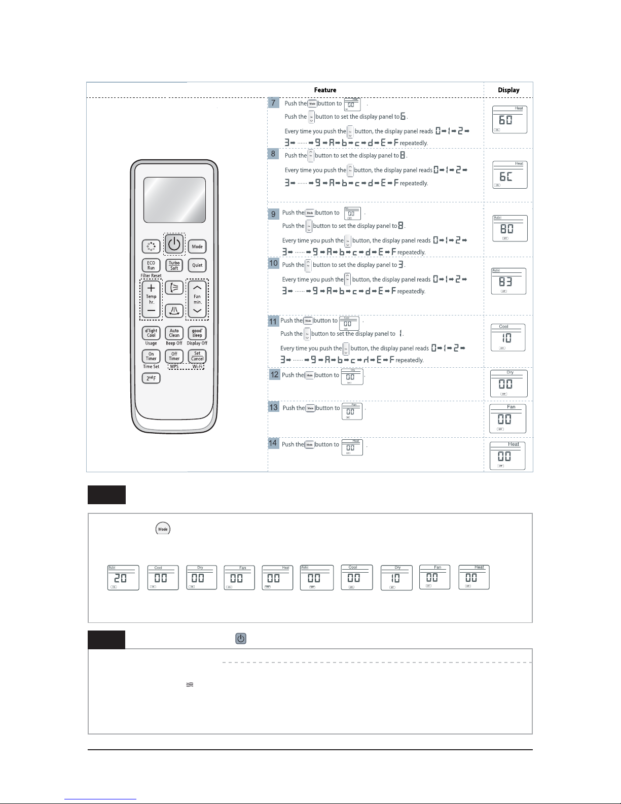
Press the Mode Selection key to set the display part and check the display part.
→
The display part shows like below when each time you press Mode button.
Step 3
Upon completion of the selection, check you made right selections.
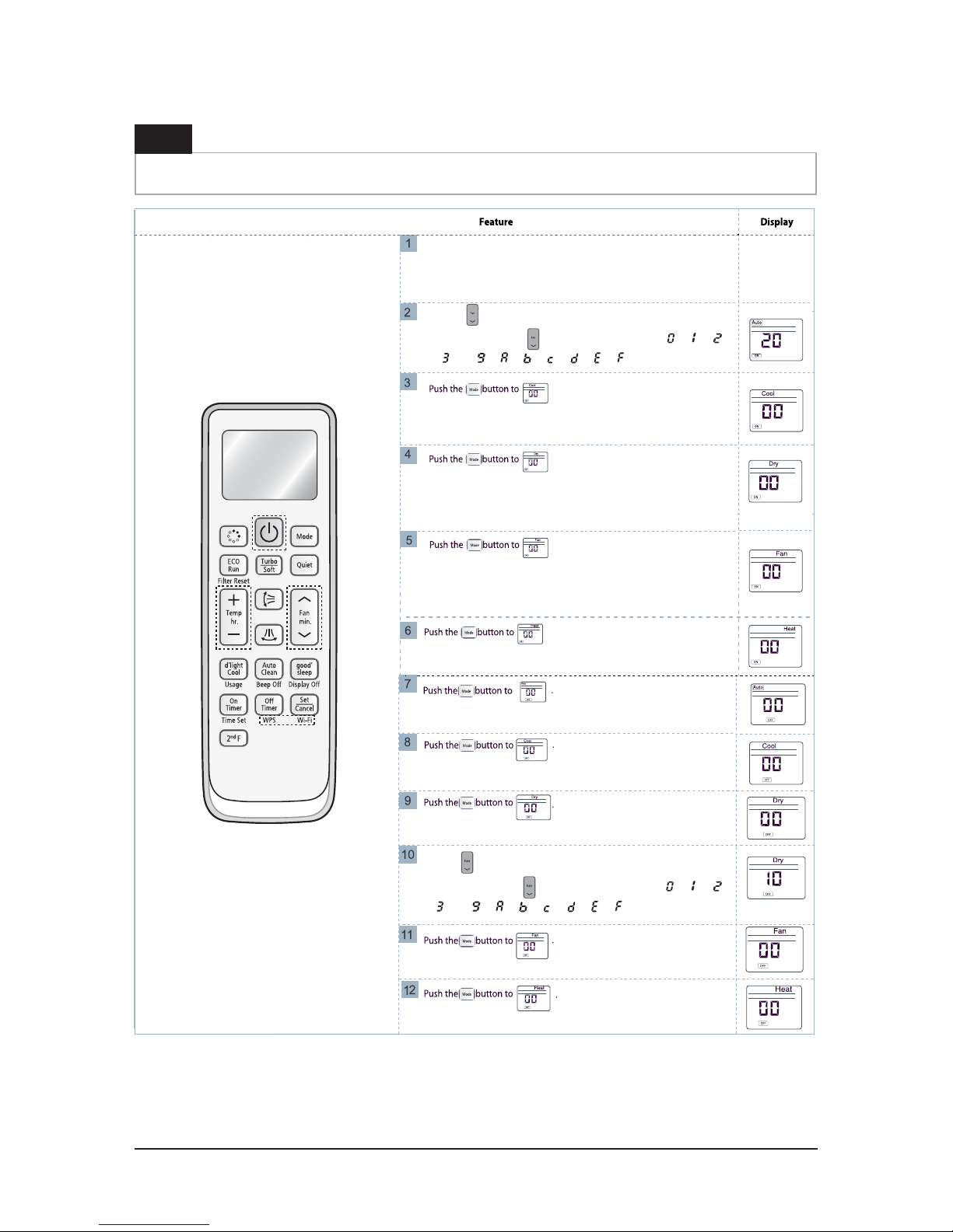
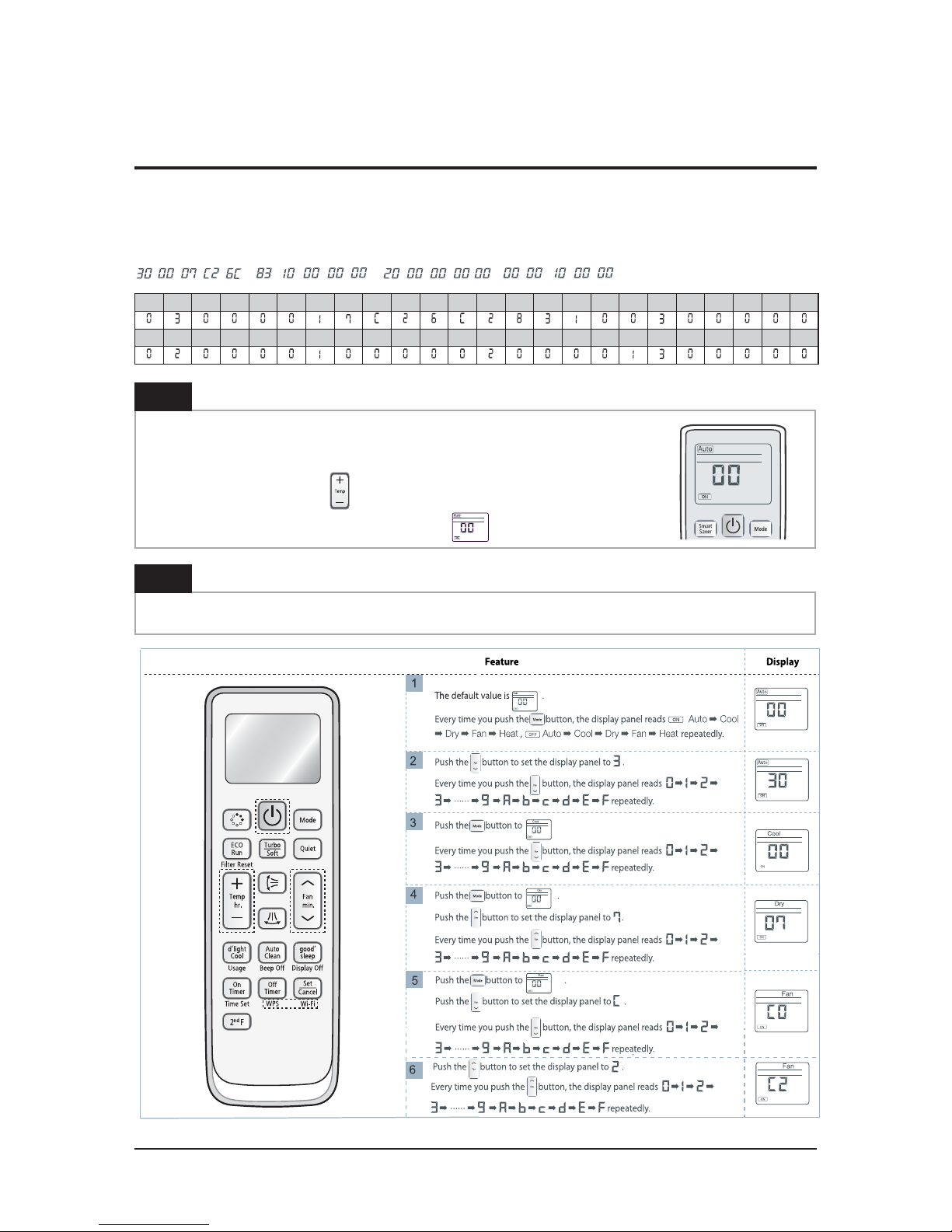
Samsung Electronics 3-7
Step 1 (Enter the Option S etup mode) is executed.
(Seg25 ~ 48 for setting remote control Setup)
Push th e
Mode button to set the display panerl to 2.
Every time you push the
button, the display panel reads
...
repeatedly.
Push th e Mode button to set the display panerl to 1.
Every time you push the
button, the display panel reads
...
repeatedly.
Step 5
Enter the Options Setup mode and select your options asscording to the following procedure.

3-8 Samsung Electronics
Press the Mode Selection key to set the display part and check the display part.
ė
The display part shows like below when each time you press Mode button.
Step 6
Upon completion of the selection, check you made right selections.
Step 7
Pressing the ON/OFF button ( ).
When pressing the operation ON/OFF key with the direction of remote control for unit, the sound ’’Ding’’ or ’’Diriring’’ is hea
and the OPERATION ICON(
) lamp of the display is flickering at the same time, then the input of option is completed.
(If the deriving sound isn’t heard, try again pressing the ON/OFF button.)
Step 8
Unit operation test-run.
First: Remove the battery from the remote control.
Second : Re-insert the battery into the remote control.
Third : Press ON/OFF key with the direction of remote control for set.
Ƶ Error mode
1. If all lamps of indoor unit are flickering, Plug out, plug in power plug again and press ON/OFF key to retry.
2. If the unit is not working properly or all lamps are continuously flickering after setting the option code, see if the c
orrect option code is
set up for its model.
ƶ Option Items
Model 1-6 7-12 13-18 19-24 25-30 31-36 37-42 43-48
AR18HSFNBWK/EU 010005 176A0A 27323C 372634 034A40 103E49 200000 300000
AR18HSSDBWK/EU 010045 196A38 27323C 371634 033F3E 102C36 200000 300001
AR24HSSDBWK/EU 010045 156A5C 274450 372634 03454F 10424A 200000 300000
AR24HSFNBWK/EU 010005 156A5C 274450 372634 03454F 10424A 200000 300000
AR24HSFSRWK/ER 010005 15625C 274450 372604 03454F 10424A 200000 300000
AR24HSFNRWK/ER 010005 15625C 274450 372604 03454F 104
24A 200000 300000
AR18HSFSRWK/ER 010005 17620A 27323C 372604 034A40 103E49 200000 300000
AR18HSFNRWK/ER 010005 17620A 27323C 372604 034A40 103E49 200000 300000
AR24FSFNAWKNFA 010005 15625C 27444E 372604 03454F 10424A 200000 300000
Samsung Electronics 3-9
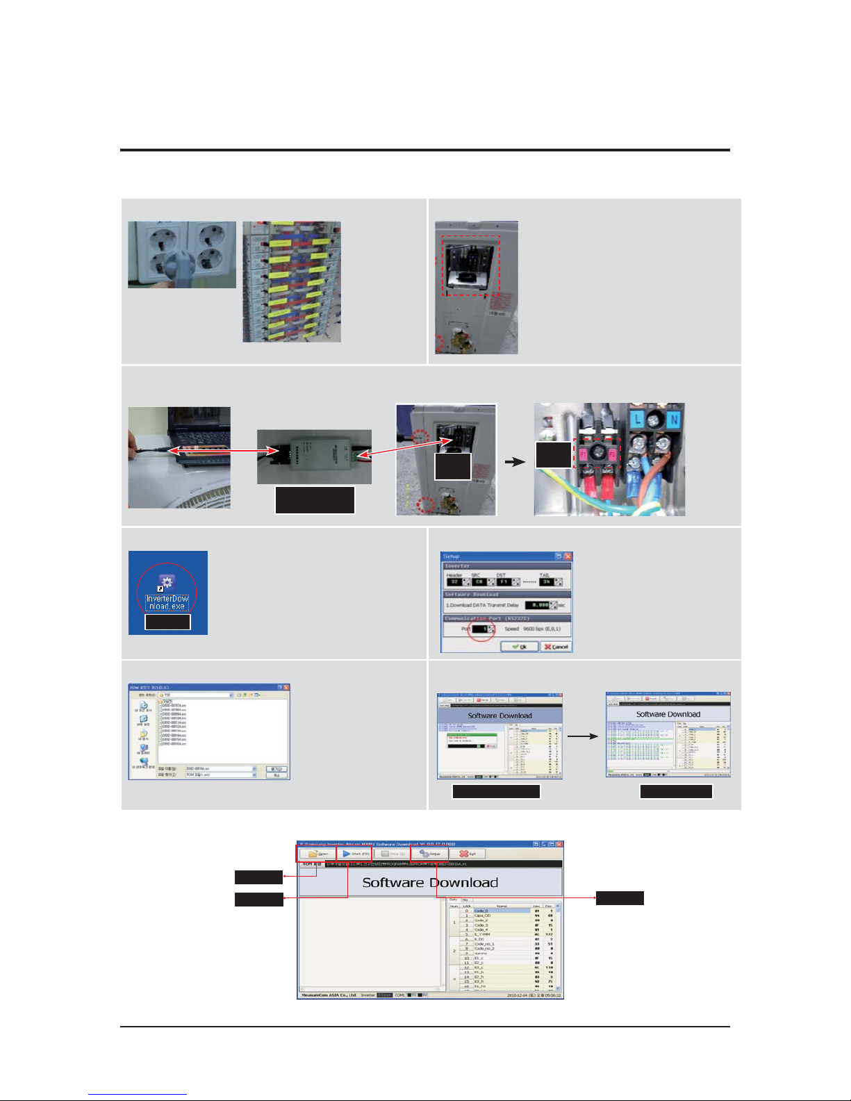
3-4 EEPROM Download (485 communication model)
Ƶ Method#1 : Using Communication line
1) Power off 2) Take off the side cover
3) Connect PC-Download Jig-PBA
F1,F2
(2pin)
F1,F2
(2pin)
RS 232 to 485
Converter
4) Execute the
Inverter Download program
4) CLICK
5) Select COM Port and connect
6) Open the file
(*.src) 7) Click the Start button and reset the power
Waiting down load Download
Reset
power
6) CLICK
7) CLICK
5) CLICK
3-10 Samsung Electronics
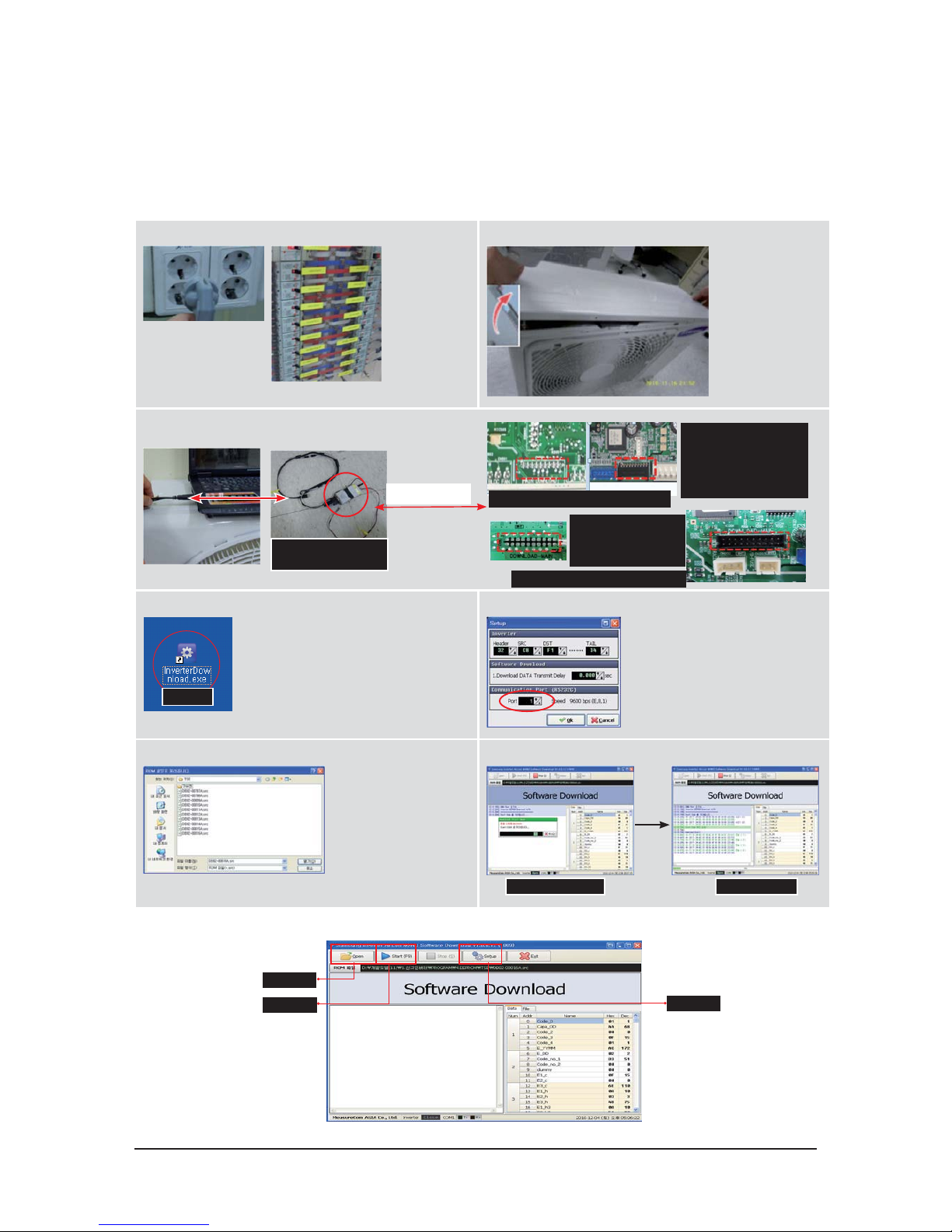
Ƶ Method#2 : Using Serial line
1) Power off 2) Take off the Cabinet : Check the LED off
3) Connect PC-Download Jig-PBA
RS 232 to Serial
Download Converter
Download connector
(10pin)
4) Execute the Inverter Download program
4) CLICK
5) Select COM Port and connect
6) Open the file (*.src) 7) Click the Start button
Waiting down load Download
6) CLICK
7) CLICK
5) CLICK
Download connector
(10pin,Black)
1)DB41-01010A : CN201
2)DB41-01129A : CN201
3)DB41-01023A : CN512
4)DB41-01081B : CN37
PIN# 1:RXD, 2:TXD, 9:GND, 10:VCC
Download connector
(20pin, Black)
1)DB41-01227A : CN201
2)DB41-01228A : CN201
PIN# 1:RXD, 2:TXD, 9:GND, 10:VCC
Samsung Electronics 4-1
4. Disassembly and Reassembly
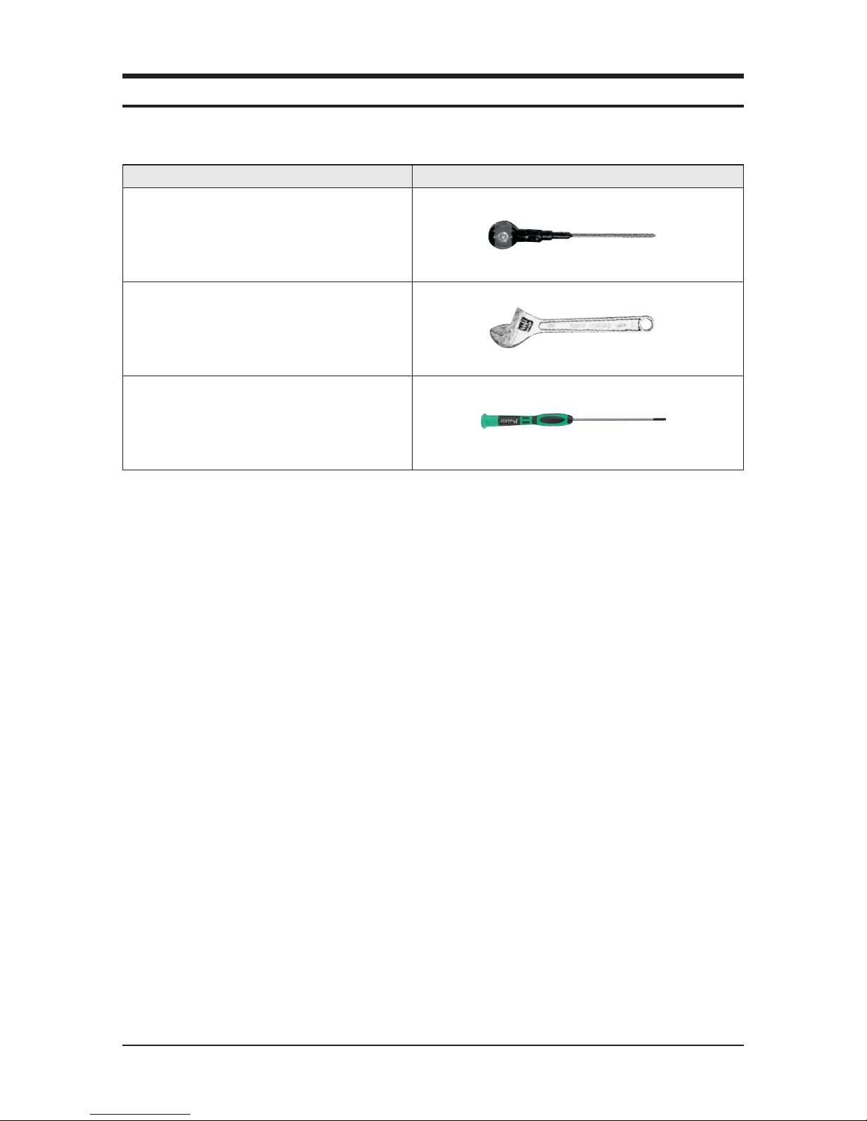
Q Necessary Tools
Item Remark
+SCREW DRIVER
MONKEY SPANNER
- SCREW DRIVER
4-2 Samsung Electronics
No Parts
Procedure Remark
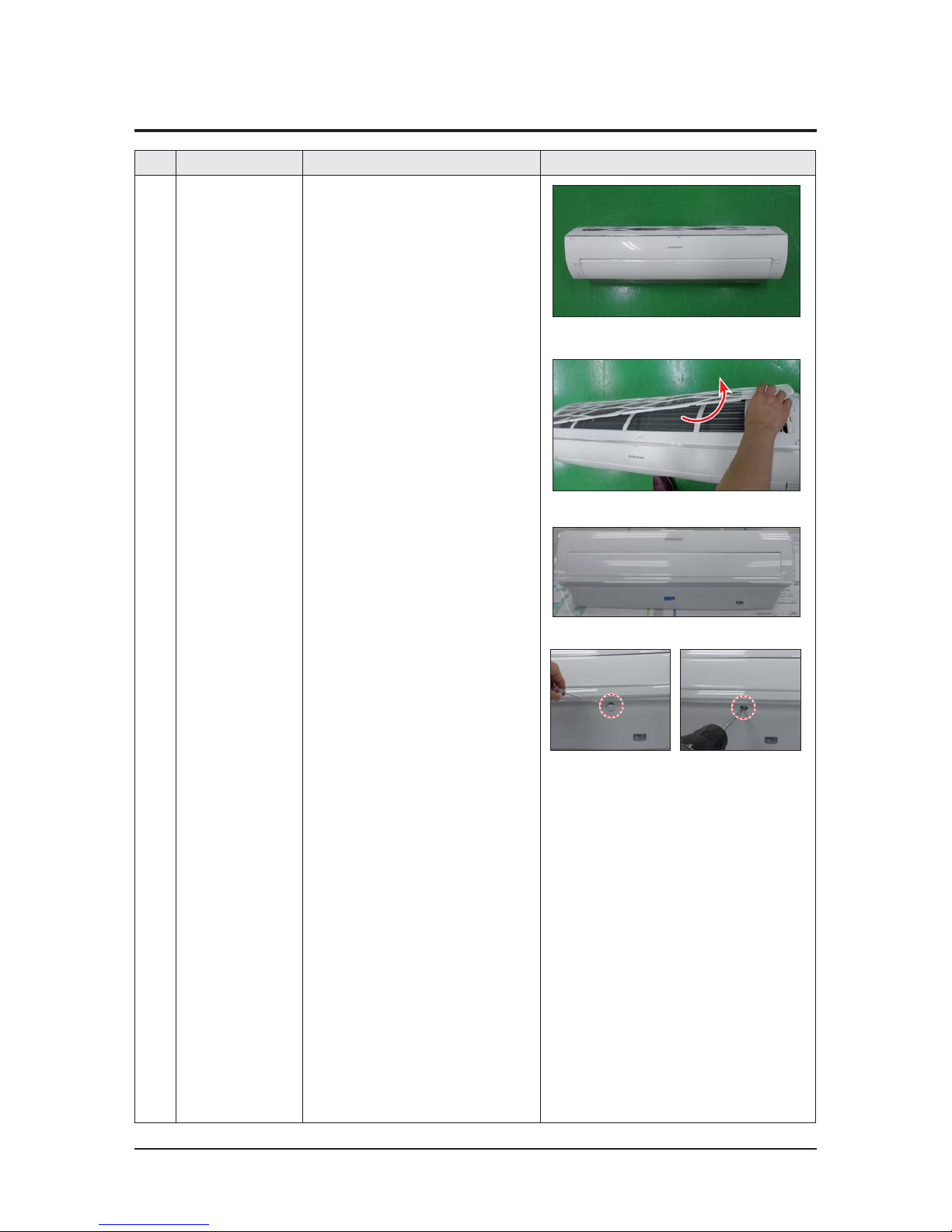
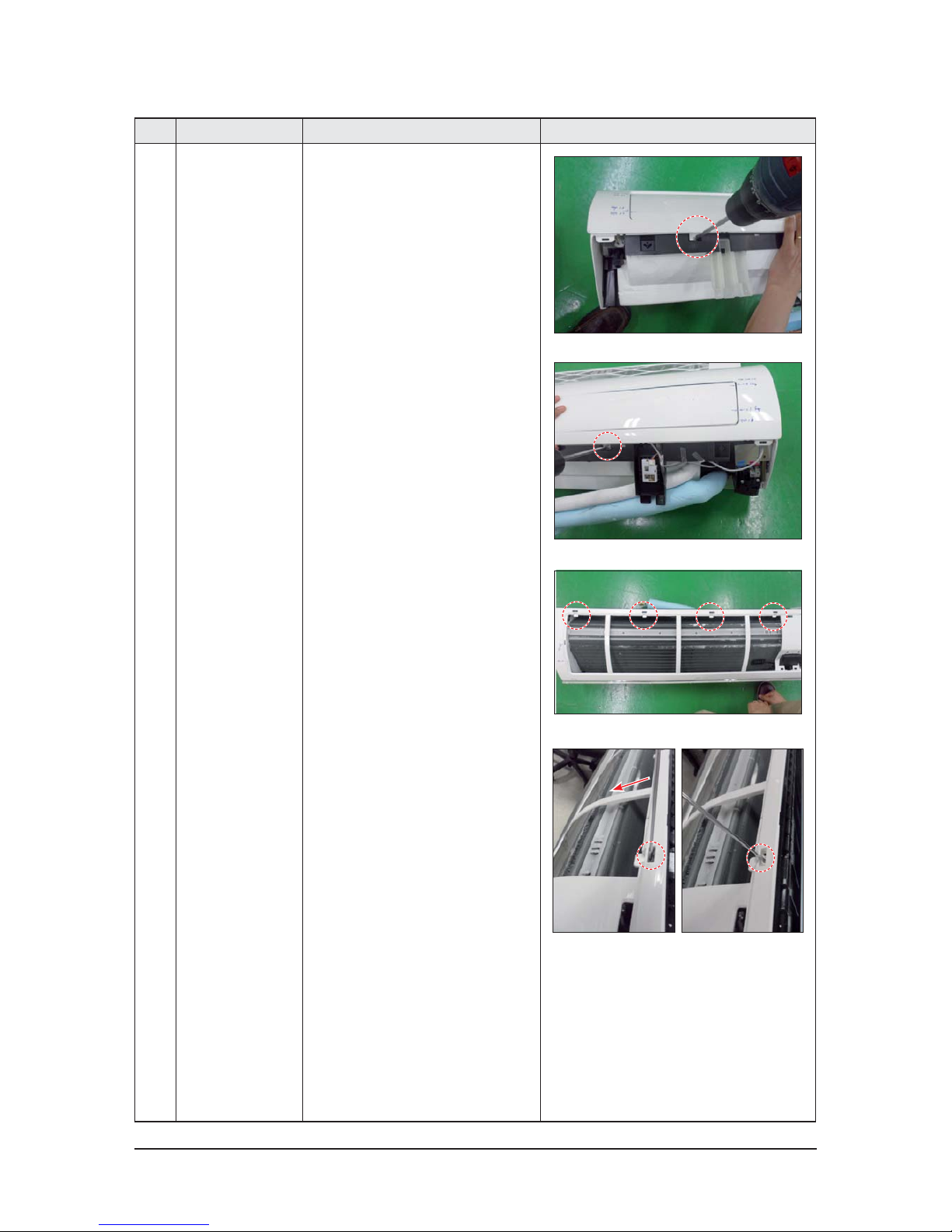
1 PANEL-FRONT 1) Stop the driving of air conditioner and shut off
main power supply.
2) Detach FILTER PRE from the PANEL FRONT.
3) Cover Panel is assembled on bottom of indoor
unit as shown in the figure.
Remove the Cap Screw as shown on the right
side and then remove the screw and separate
the Cover Panel.
4-1. Indoor Unit
Samsung Electronics 4-3
No Parts
Procedure Remark
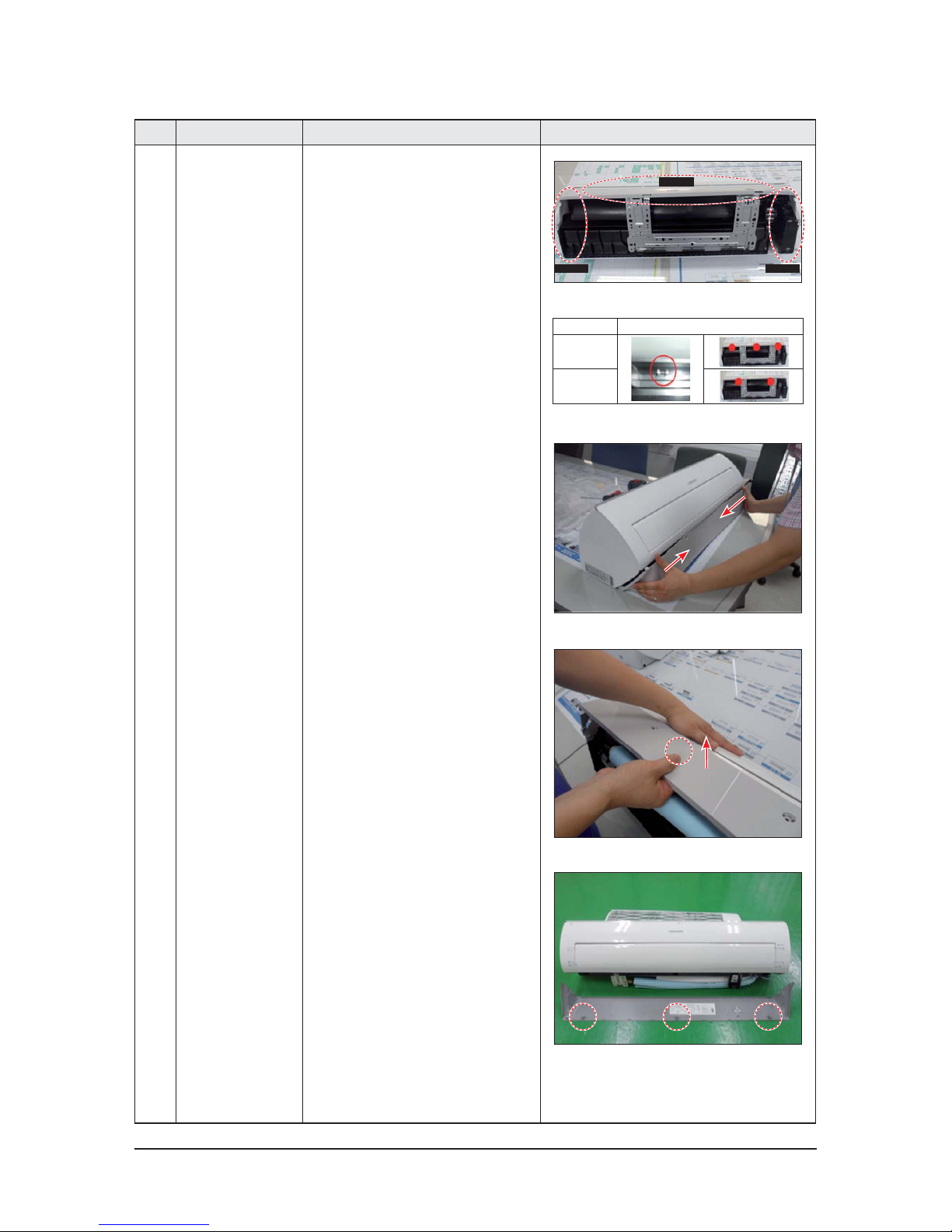
4) Cover Panel is fixed to body by Hook in center
area and side area.
5) Separate the hook after pushing both end of
Cover Panel as shown in the figure.
(Watch out for the damage of the hook)
6) Raise front part upward obliquely as shown in
the figure and then remove the hooks.
Center area
Side area
Side area
HOOK
9/12K
18/24/30K
4-4 Samsung Electronics
No Parts
Procedure Remark
Caution:
Assembly of Cover Panel after service end.
-
Reassembly is in the reverse order of the
removal.
- Piping and drain hose must be careful not to
damage and Progress must be done with both
hands.
Hook (Side)
Hook (Center)
Screw
Cap Screw
Samsung Electronics 4-5
No Parts
Procedure Remark
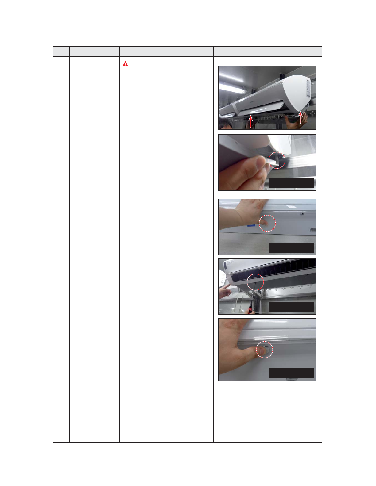
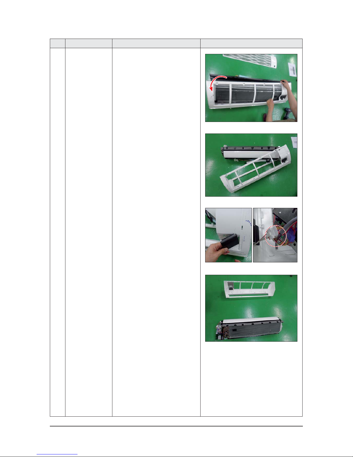
7) To detach the PANEL-FRONT from the main
frame, unfasten 2 screws at the bottom.
(use + Screw Driver)
8) To detach the COVER-PANEL from the main
frame, loosen 4 HOOK Structures.
When separate the hook :
Use the (-) screw Driver.
(-)Screw Driver Insert the hook and then pull the
hook as shown on the right side.
(Watch out for the damage of the hook)
4-6 Samsung Electronics
No Parts
Procedure Remark
9) Remove the Panel Frame from the Main
Frame as shown on the right side.
10) Remove the WIFI KIT connector.
WIFI KIT connector is located of Panel Front.
(For model with WIFI KIT)
Samsung Electronics 4-7
No Parts
Procedure Remark
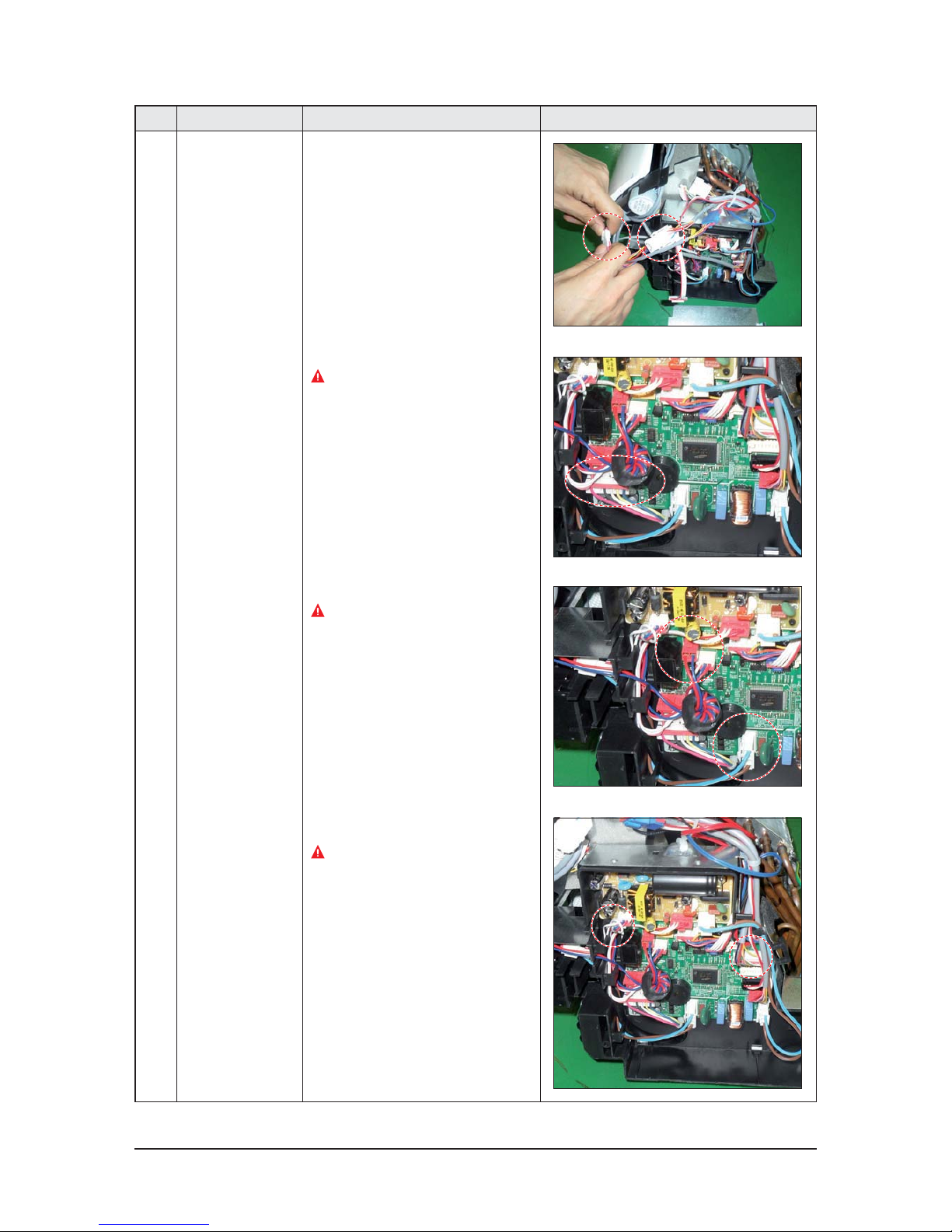
2
CONTORL IN
5) Loosen Stepping MOTOR Wire / BLADE Wire.
6) Loosen MOTOR Wire.
Caution:
When you separate the connector,
pull pressing the locking button.
7) Loosen the terminal block wires.
Caution:
When you separate the connector,
pull pressing the locking button.
8) Loosen the Thermistor wire connector,
Display wire connector.
Caution:
When you separate the connector,
pull pressing the locking button.
4-8 Samsung Electronics
No Parts
Procedure Remark
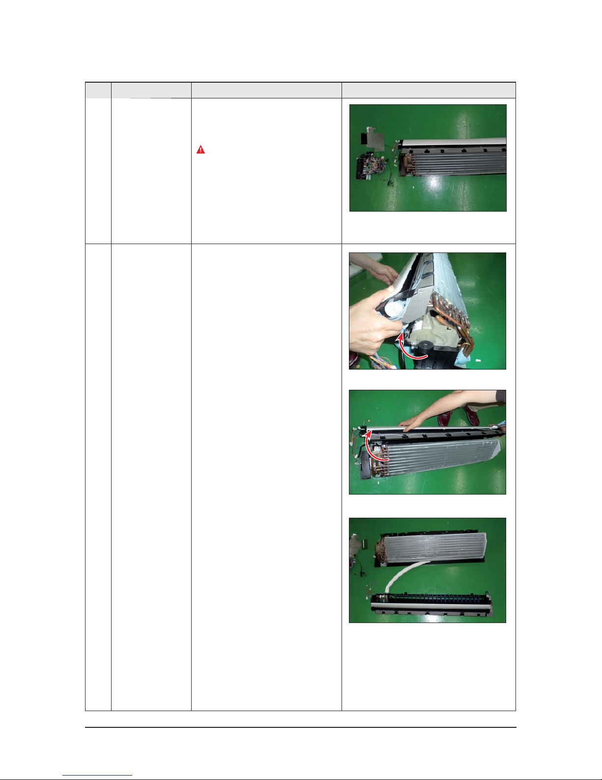
5 EVAPORATOR 9) Take off the CASE-CONTROL from
the main frame after loosen the remaining
connector.
Caution:
When you separate the connector,
pull pressing the locking button.
3 TRAY DRAIN 1) To detach TRAY-DRAIN from the main frame,
pull the bottom of the TRAY-DRAIN towards
you.
Samsung Electronics 4-9
No Parts
Procedure Remark
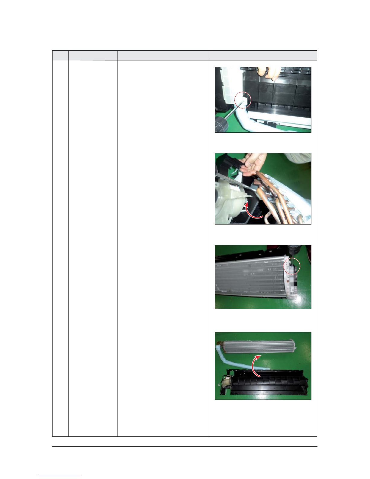
4 Evaporator 1) Detach the HOLDER PIPE.
2) Unfasten the screw at the left side.
(use + Screw Driver)
3) Unfasten the screw at the right side.
(use + Screw Driver)
4) To detach Evaporator from the main frame,
pull the bottom of the Evaporator towards
you.
4-10 Samsung Electronics
No Parts
Procedure Remark
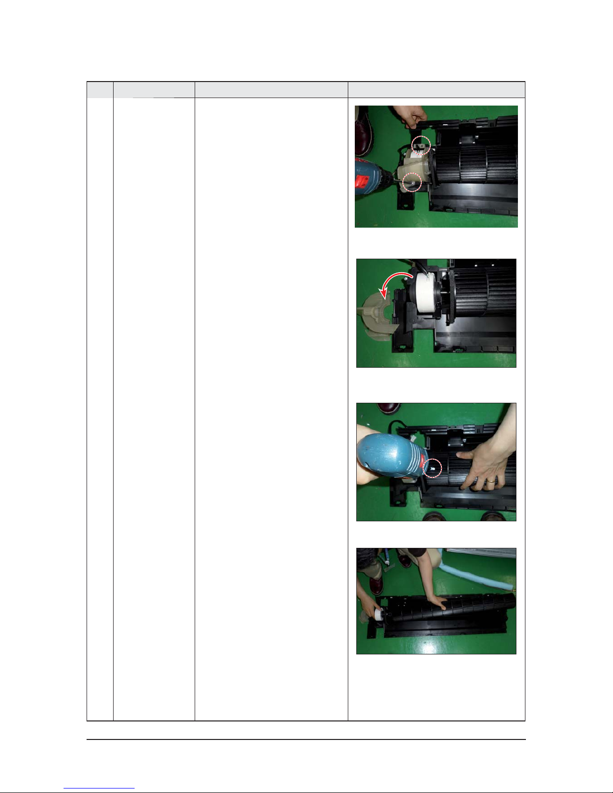
5 FAN MOTOR
&
CROSS FAN
1) Unfasten the screw. (use + Screw Driver)
2) Detach the FAN Motor case.
3) Unfasten the screw a little.
(use + Screw Driver)
4) Pull the CROSS-FAN to the left side.
 Loading...