

Samsung AQ18A9, AQ24A1, UQ18A9, UQ24A1 Service manual
Manual
SERVICE
SPLIT TYPE AIR CONDITIONER
Indoor Unit
AQ18A9(0)RCF
AQ24A1(2)RC
Outdoor Unit
UQ18A9(0)RCF
UQ24A1(2)RC
E DB98-15778A(2)
Safety Precautions
The following safety precautions must be taken when using your air conditioner.
WARNING
I
NSTALLING THE UNIT
POWER SUPPLY LINE
FUSE OR CIRCUIT
BREAKER
Risk of electric shock. • Can cause injury or death. • Disconnect all remote electric
power supplies before servicing, installing or cleaning. • This must be done by the
manufacturer or its service agent or a similar qualified person in order to avoid a
hazard.
◆ The unit should not be installed by the user. Ask the dealer or authorized
company to install the units except room air conditioners for the U.S.A and
Canada area.
◆ If the unit is installed improperly, water leakage, electric shock or fire may
result.
◆ The air conditioner must be installed in accordance with national wiring
regulations and safety regulations wherever applicable.
◆ Mount with the lowest moving parts at least 8.2ft(2.5m) above the floor or
grade level. (If applicable)
◆ The manufacturer does not assume responsibility for accidents or injury
caused by an incorrectly installed air conditioner. If you are unsure about
installation, contact an installation specialist.
◆ When installing the built-in type air conditioner, keep all electrical cables
such as the power cable and the connection cord in pipe, ducts, cable
channels e.t.c to protect them against liquids, outside impacts and so on.
◆ If the power cord of this air conditioner is damaged, it must be replaced by
,
the manufacturer, its service agent or similarly qualified persons in order to
avoid a hazard.
◆ The unit must be plugged into an independent circuit if applicable or
connect the power cable to the auxiliary circuit breaker. An all pole
disconnection from the power supply must be incorporated in the fixed
wiring with a contact opening of >3mm.
◆ Do not use an extension cord with this product.
◆ If the unit is equipped with a power supply cord and a plug, the plug must
be accessible after installation.
◆ This appliance must be installed accordance with the national wiring
regulations.
2
Contents
Ι
DISASSEMBLE AND REASSEMBLE
1. Indoor unit
2. Outdoor unit
ΙΙ
S
ET UP THE OPTION CODE 12
ΙΙΙ
TROUBLESHOOTING
1. Items to be checked first
2. Abnormal diagnosis by symptom
3. Replace PCB module
ΙΛ
ASSEMBLY DRAWING AND
1. Indoor unit
2. Outdoor unit
3. PCB Box
PART’S LIST
Λ
REFRIGERATING CYCLE BLOCK DIAGRAM 29
4
8
15
16
21
22
24
28
Λ
Ι
PERFORMANCE CURVE 30
Λ
ΙΙ
PCB DIAGRAM 36
ΛΙΙΙ
WIRING DIAGRAM
1. Indoor unit
2. Outdoor unit
ΙΧ
SCHEMATIC DIAGRAM
1. Indoor unit 41
SPLIT TYPE
38
39
AIR CONDITIONER
3
Ι
Disassemble and reassemble
Stop operation of the air conditioner and remove the power cable before repairing the unit.
1 Indoor unit
If you disassemble the heat exchanger, you must pump down at first.
No. Part Procedure Remark
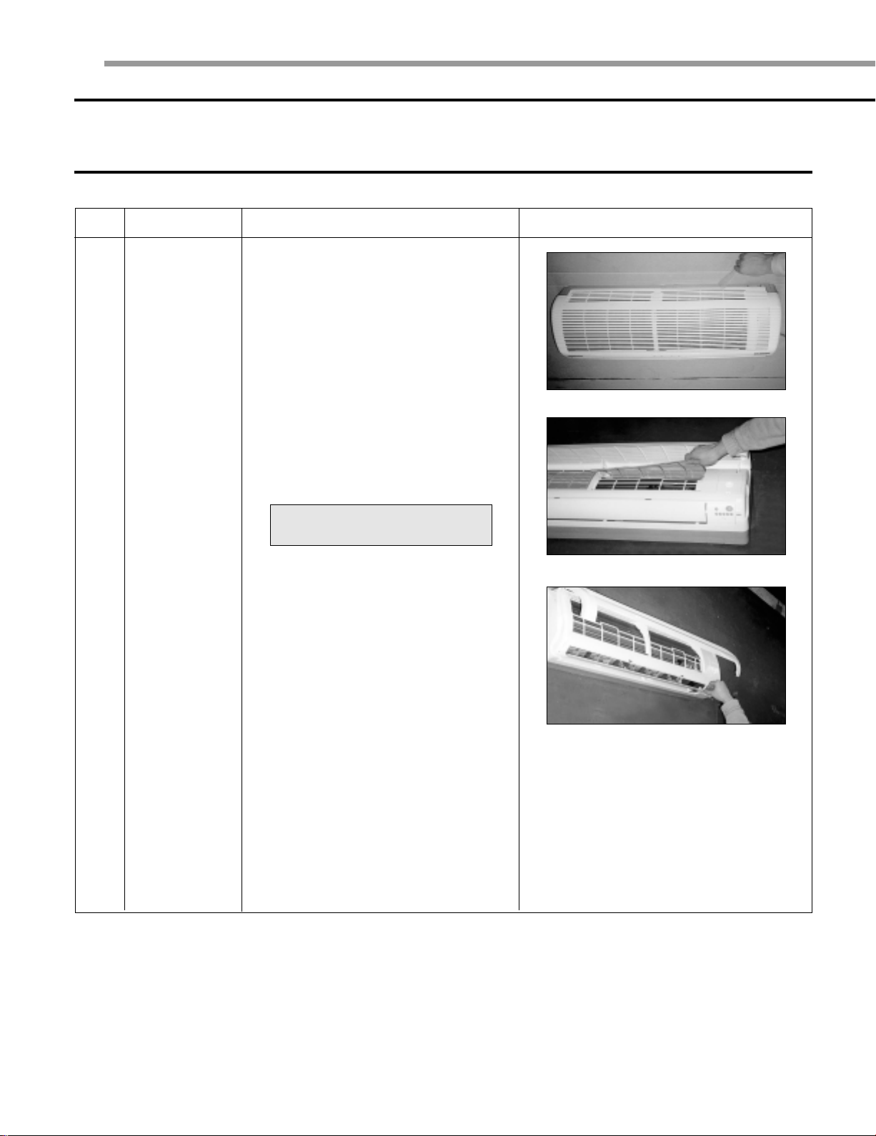
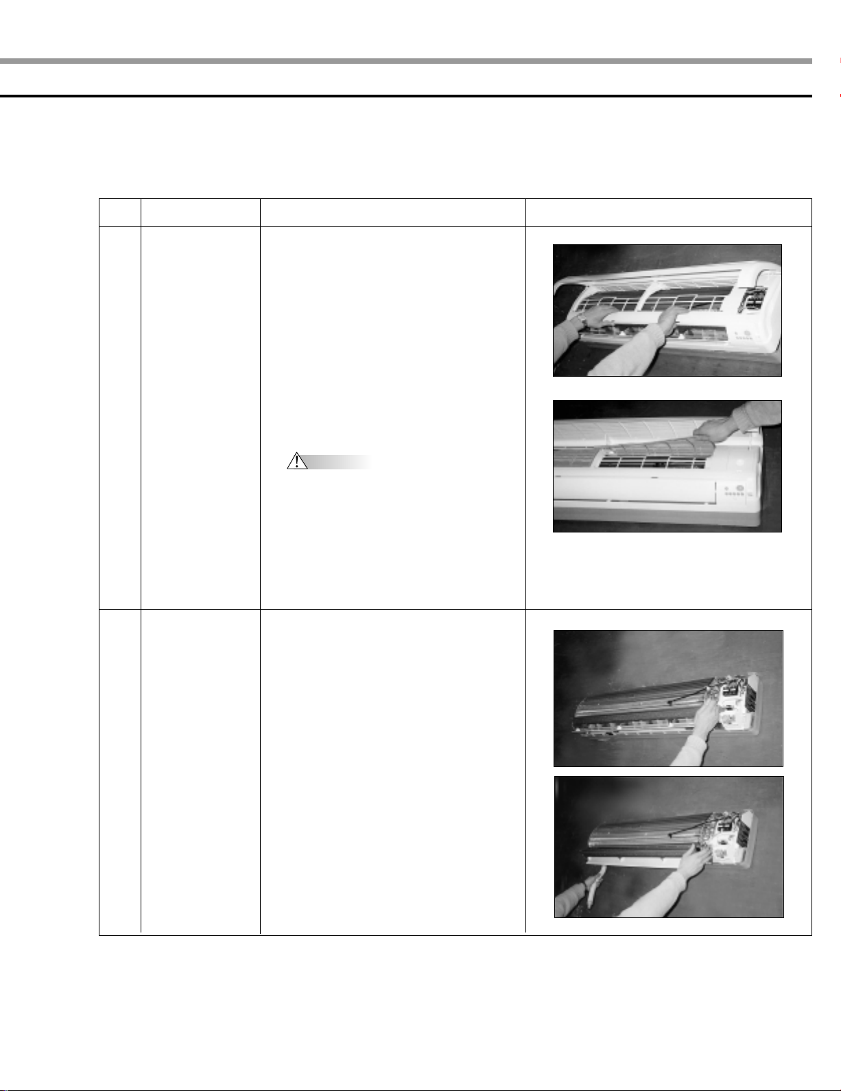
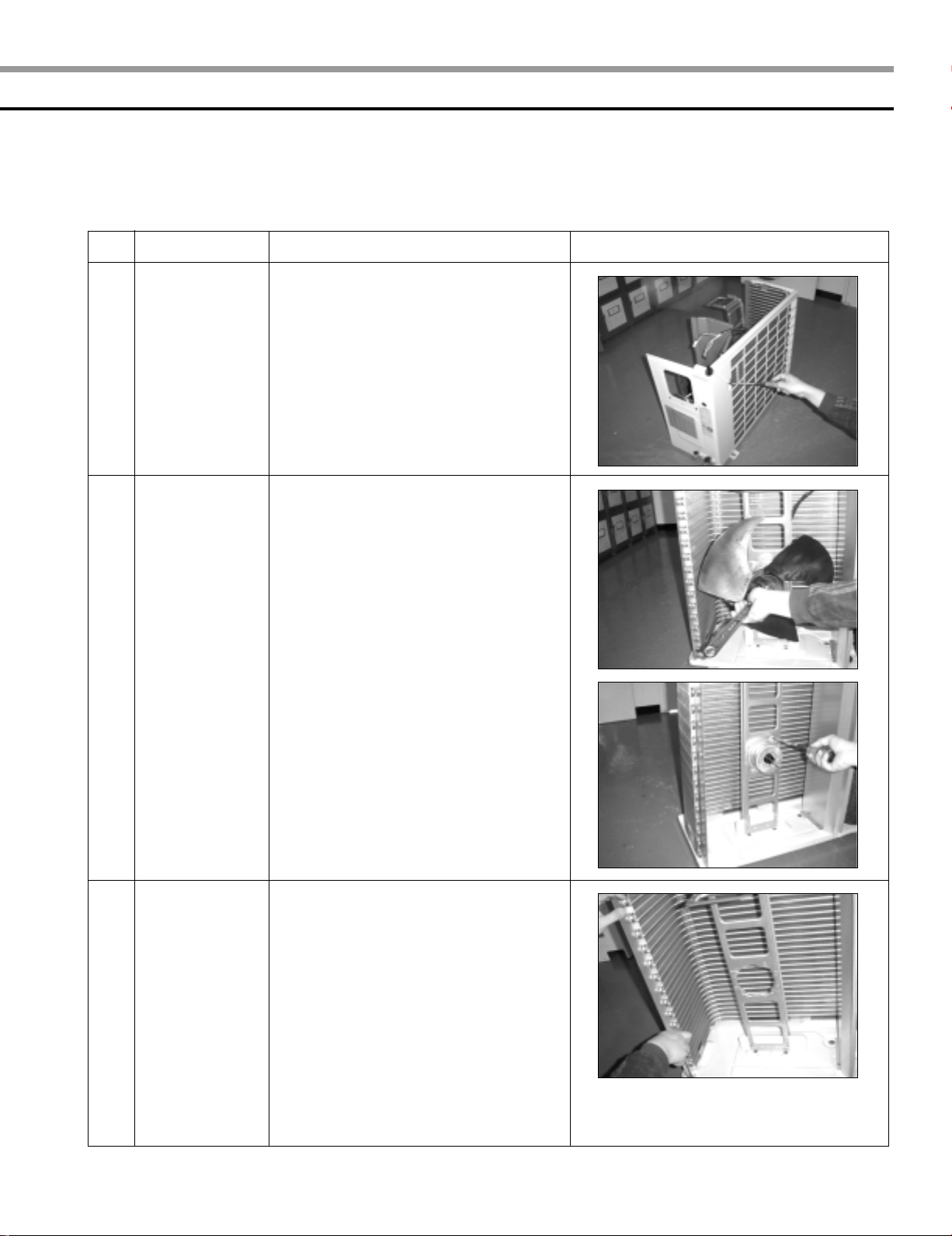
1
Front Panel
1) Stop the operation of the air conditioner
and block the main power.
2)Separate the tape from the front panel.
3)Contract the second finger to the left,
and right handle. And pull the inlet grille
to open.
4)Take the left and right filter out.
*Taking off the deodorizing and
Electrostatic filter out. (Option)
5)Loosen one of the right screw and
separate the terminal cover.
6)Loosen three screws of front grille.
4
No.
Part
Procedure Remark
1
2
Front Panel
Assembly Tray
Drain
7)Pull the upper left and right of discharge
softly so that the outside cover is
pulled out.
8)Pull softly the lower part of discharge and
push it up.
Caution
Assemble the front panel and fix the
hooks of left and right.
1) Separate the drain hose from the
extension drain hose.
2) Take the display PCB out.
(Center of the indoor unit)
3) Pull tray drain out from the back body.
5
Ι
Disassemble and reassemble (cont’d)
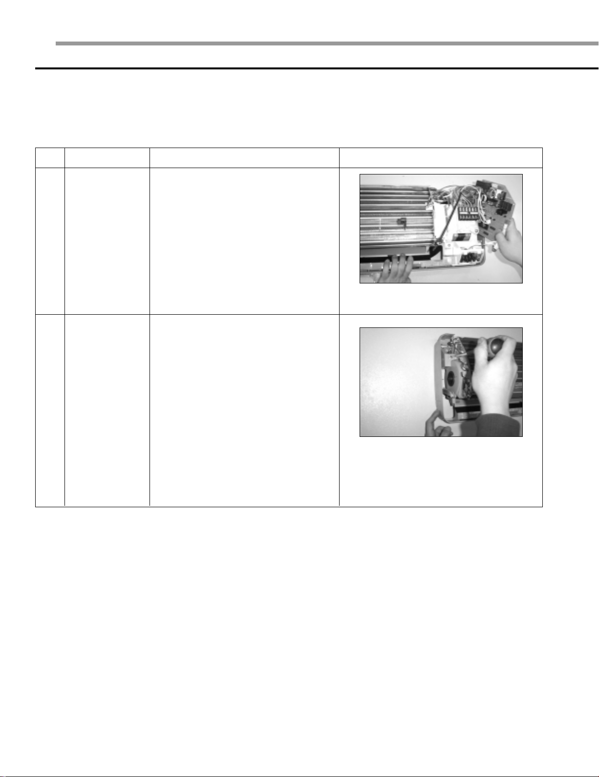
No.
3
4
Part
Electrical
Parts
(Main PCB)
Heat
Exchanger
Procedure Remark
1) Take out all the connector of PCB
on the upper part.
2) Separate the outdoor unit connection wire
from the terminal block.
3) If you pull out the main PCB up, it will be
taken out.
1) Loosen two ground screws at the right
side.
2) Separate the connection pipe.
3) Separate the bush body at the upper
side and holder at the rear side.
4) Loosen the two screws at the left side.
5) Lift the heat exchanger up a little to push
the upper side to separate it from the
indoor unit.
6
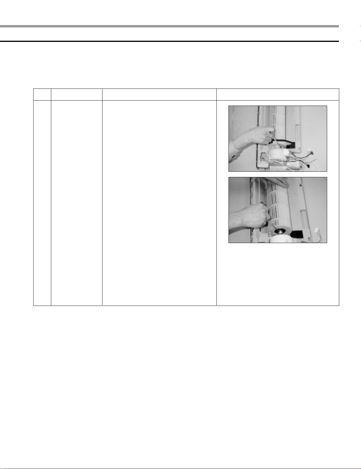
No.
Part
Procedure Remark
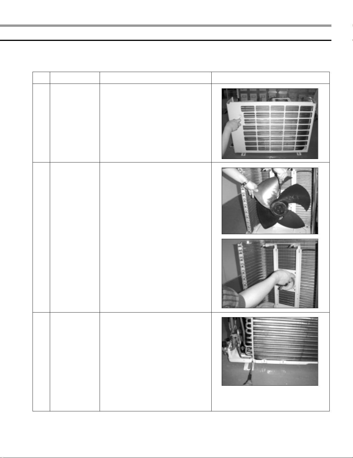
5
Fan Motor and
Cross Fan
1) Loosen two screws and separate the
motor holder.
2) Loosen the screw of fan motor.
(By use of M3 wrench)
3)Separate the fan motor from the fan.
4)Separate the fan from the left holder
bearing.
7
Ι
Disassemble and reassemble (cont’d)
2 Outdoor unit
■ UQ18A9(0)RCF
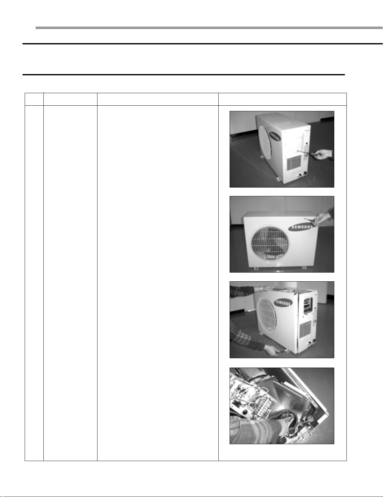
No. Part Procedure Remark
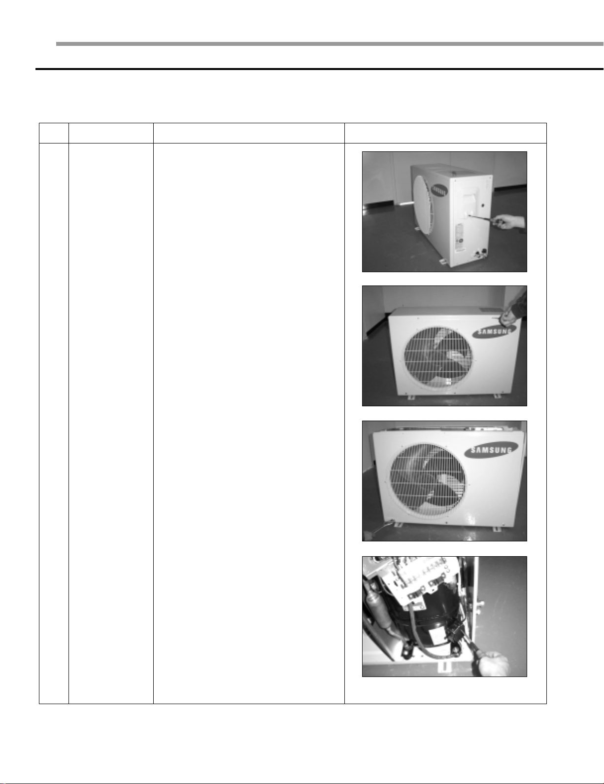
1
Common Work
1)Loosen the fixing screws and separate
the cover control.
2)Separate the connection wire from the
terminal block.
3)Loosen the fixing screws and separate
the upper cabinet.
4) Loosen the fixing screws and separate
the front cabinet.
5) Loosen two screws and pull up the
control box.
6) Loosen the nut on the terminal cover
and open it.
7)Separate the comp lead wire.
8
No. Part Procedure Remark
1
2
Common Work
Fan and Motor
8)Loosen the fixing screws and separate
the cabinet side.
1) Remove the nut flange
(Turn to the clockwise).
2) Separate the fan.
3) Loosen four screws to separate
the motor.
Heat Exchanger
3
and Compressor
1) Release the refrigerant at first.
2) Disassemble the inlet and outlet pipe-
by welding.
3) Loosen the fixing screws of the heat
exchanger.
4) Separate the heat exchanger.
5) Loosen three bolts of the compressor.
6) Separate the compressor.
9
Ι
Disassemble and reassemble (cont’d)
■ UQ24A1(2)RC
No. Part Procedure Remark
1
Common Work
1)Loosen the fixing screws and separate
the cover control.
2)Separate the connection wire from the
terminal block.
3)Loosen the fixing screws and separate
the upper cabinet.
4) Loosen the fixing screws and separate
the front cabinet.
10
5) Loosen three screws and pull up the
control box.
6) Separate the terminal cover and
separate the comp lead wire.
No. Part Procedure Remark
1
2
Common Work
Fan and Motor
7)Loosen the fixing screws and separate
the cabinet side.
1) Loosen the fixing bolt and separate
the fan.
2) Loosen four fixing bolts to separate
the motor.
Heat Exchanger
3
and compressor
1) Release the refrigerant at first.
2) Disassemble the inlet and outlet pipe
by welding.
3) Loosen the fixing screws of the heat
exchanger.
4) Separate the heat exchanger.
5) Loosen four bolts of the compressor.
6) Separate the compressor.
11
ΙΙ
Set up the option code
The method for setting up the model option with the remote control
◆ It is necessary to set up option codes after replacing the main PCB with service parts.
Make sure that you can set up option codes of the remote control after replacing the main PBA.
Otherwise, the unit won’t be working properly and all LED lamps on display will be flickering.
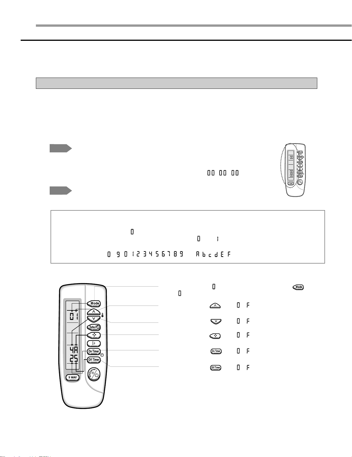
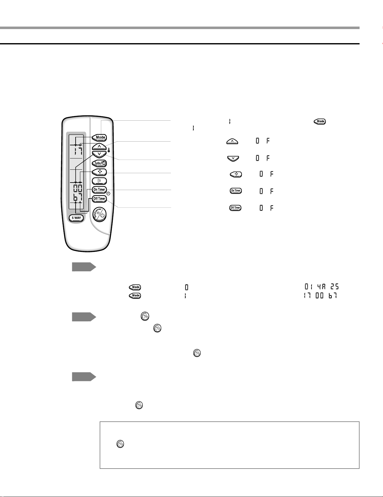
Step 1
Step 2
NNNNoooottttee
Preparing for the remote control to the main PCB option set.
1. Remove the battery from the remote control.
2. Press the temperature button simultaneously and insert the battery again.
3. Make sure the remote control display shown as .
Preparing for the remote control option set.
ee
In case that the wrong letter has been selected; continue to press the button until the
correct letter appears.
1. If the number “ ”appears on the display, proceed to the second stage.
2. Every time you press the 1) and 7) button, “ ” and “ ” continue to appear.
3. Every time you press the 2), 3), 4), 5), 6), 8), 9), 10), 11), 12) button, the number increases
from ~ ( , , , , , , , , , ) and , , , , , in order.
1) If the first number is , it is correct. Otherwise, press the button
until appears.
2) When pressing the button ~ on the display, select one of them.
12
3) When pressing the button ~ on the display, select one of them.
4) When pressing the button ~ on the display, select one of them.
5) When pressing the button ~ on the display, select one of them.
6) When pressing the button ~ on the display, select one of them.
7) If the first number is , it is correct. Otherwise, press the button
until appears.
8) When pressing the button ~ on the display, select one of them.
9) When pressing the button ~ on the display, select one of them.
10) When pressing the button ~ on the display, select one of them.
11) When pressing the button ~ on the display, select one of them.
12) When pressing the button ~ on the display, select one of them.
Step 3
Step 4
Step 5
NNNNoooottttee
Reconfirming the option set after completing
Example : 014A25-1700b7
Press the button for the “ ” mode and the display will be shown as .
Press the button for the “ ” mode and the display will be shown as .
Pressing the (On/Off)button
When pressing the (On/Off)button in the direction of the remote control for unit,
it sounds beep or ringing and the first LED (STANDARD)lamp on the left side is
flickering at the same time, then the input option is completed. If it doesn’t sound
ringing, try again by pressing the (On/Off)button.
Testing the unit
1 Remove the battery from the remote control.
2. Insert the battery into the remote control.
3. Press the (On/Off)button in the direction of the remote control for set.
Error mode
ee
1. If all lamps of the indoor units are flickering, plug out and in again and press the
(On/Off) button again.
2. If the unit doesn’t work properly or all lamps are continuously flickering after setting the option
code, check that the option code is set properly for its own model.
13
 Loading...