

SAMSUNG AQ07A1VE Service Manual Troubleshooting
5. Troubleshooting
5-1 Items to be checked first
1 ) The input voltage should be rating voltage 10% range.
The airconditioner may not operate properly if the voltage is out of this range.
2 ) Is the link cable linking the indoor unit and the outdoor unit linked pro p e r l y ?
The indoor unit and the outdoor unit shall be linked by 5 cables.
Check the terminals if the indoor unit and outdoor unit are properly linked by the same number of cables.
Otherwise the airconditioner may not operate pro p e r l y.
3 ) When a problem occurs due to the contents illustrated in the table below it is a symptom not related to the
malfunction of the airc o n d i t i o n e r.
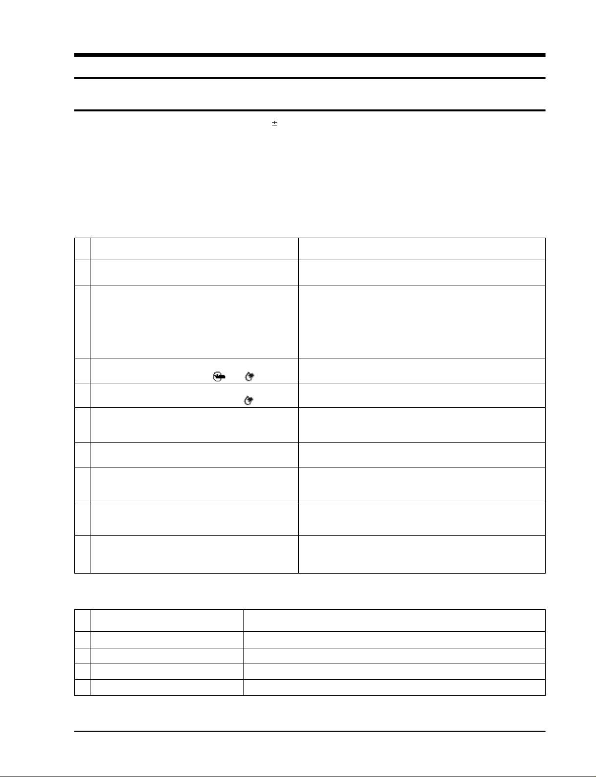
NO Operation of air conditioner
1 The STD operation indication LED blinks when a
power plug of the indoor unit is plugged in for the first time.
2 In a COOL operation mode, the compressor does not
operate at a room temperature higher than the setting
temperature that the IN DOOR FAN should operate.
In a HEAT operation mode, the compressor does not
operate at a room temperature lower than the setting
temperature that indoor fan should
operate.
3 Fan speed setting is not allowed in AUTO or DRY mode.
4 Compressor stops operation intermittently in DRY mode.
5 Compressor of the outdoor unit is operating although it is
turned off in a HEAT mode.
6 Timer LED only of the indoor unit lights up and the
air conditioner does not operate.
7 The compressor and indoor fan stop intermittently in HEAT
mode.
8 Indoor fan and outdoor fan stop operation intermittently in
a HEAT mode.
9 The compressor stops intermittently in a COOL mode or DRY
mode, and fan speed of the indoor unit decreases.
Explanation
It indicates power is on. The LED stops blinking if the operation
ON/OFF button on the remote control unit is pushed.
In happens after a delay of 3 minutes when the compressor is reoperated. The same phenomenon occurs when a power is on.
As a phenomenon that the compressor is reoperated after a delay of
3 minutes, the indoor fan is adjusted automatically with reference
to a temperature of the air blew
The speed of the indoor fan is set to LL in DRY mode.
Fan speed is 5 steps is selected automatically in AUTO mode.
Compressor operation is controlled automatically in DRY mode
depending on the room temperature and humidity.
When the unit is turned off while de-ice is activated, the compressor
continues operation for up to 9 minutes (maximum) until the deice is
completed.
Timer is being activated and the unit is in ready mode.
The unit operates normally if the timer operation is cancelled.
The compressor and indoor fan stop intermittently if room temperature
exceeds a setting temperature in order to protect the compressor from
overheated air in a HEAT mode.
The compressor operates in a reverse cycle to remove exterior ice in a
HEAT mode, and indoor fan and outdoor fan do not operate intermittently for within 20% of the total heater operation
The compressor stops intermittently or the fan speed of the indoor unit
decreases to prevent inside/outside air frozen depending on the
inside/outside air temperature.
4 ) Indoor unit observes operation condition of the air conditioner, and displays self diagnosis details
on the display panel.
NO Display
1 STD LED blinking (1Hz)
2 TIMER LED blinking (1Hz)
3 STD and TIMER LED blinking (1Hz)
4 NATURE LED blinking (1Hz)
Samsung Electronics
Restore from power failure (input initial power)
Indoor unit Room sensor Error (open or short)
Indoor unit heat exchanger temperature sensor Error (open or short)
Indoor fan malfunctioning (for spead is Below 450rpm)
Self Diagnosis
5-1
5-2 Fault Diagnosis by Symptom
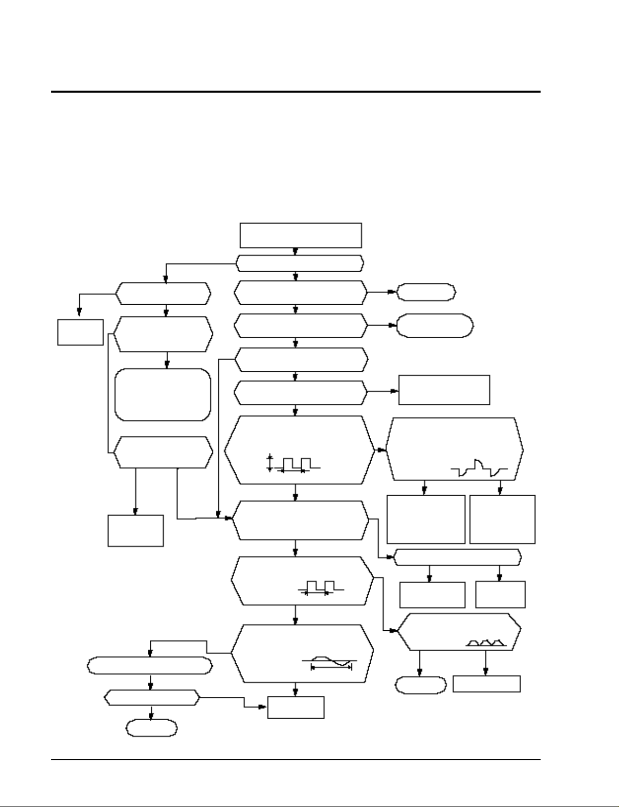
5-2-1 No Power (completely dead)-Initial diagnosis
1) Checklist :
(1) Is input voltage normal?
(2) Is AC power linked corre c t l y ?
(3) Is output voltage of DC regulator IC KA7805 (IC02) normal? (4.5VDC-5.5VDC)
2 ) Troubleshooting pro c e d u re
Remove power cord and plug in
again in approx. 5 seconds
YES
Replace PCB
display
Is DC voltage of PCB
display normal?
NO
Is rating voltage ±10% range
applied to the primary side(~,~)
of the “BD71”
NO
•Check linkage between
power cord and
terminal tap
•Check fuse
Is 325VDC appear in the
secondary side (+, -)
of “BD71”
YESNO
Replace
SMPS PARTS
Replace resonator (X301)
Is operation normal?
YES
OK
NO
Is operation lamp blinking?
Does operation start when
ON/OFF button on the remote
controller unit pushed?
Is transmission display of the
remote controller unit blinking?
Is "beep"sound heard from the main
NO
Is DC voltage of the PCB module
Are voltages of #8 (compressor),
#7(4 way valve) and #6 (outdoor fan)
Is voltage of #60 (indoor fan) of the
DC5V
Is voltage at #50 terminal of the Micom normal?
Is voltage at #18 terminal of the Micom normal?
Is voltage at #52 terminal of the micom
Are voltage at #48 and #49 of the
NO
NO
normal?
of the micom normal? 5VDC
micom normal?
10ms
normal?
micom normal?
Replace
micom
unit?
YES
NO
YES
YES
YES
NO
YES
10ms
YES
YES
250ms
0VDC
5VDC
NO
YES
NO
NO
YES
NO
Normal
Refer to remote control
unit fault diagnosis
Replace PCB
module.
Are voltages at RY71(Compressor)
RY73(4-way valve) and RY72(outdoor fan)
normal? DC12V
Is voltage at SS71(indoor fan)
YES
Check connections
compressor 4-way
valve, outdoor fan
and indoor fan.
Is output voltage of ICO2 normal?
YES
Check PCB pattern .
Replace main PCB.
Is voltage output terminal of
TLP180(PC02) normal?
YES
OK
NO
Replace
RY71, RY73,
RY72 and
SS71
NO
Replace ICO2
NO
Replace TLP180(pc02)
5-2
Samsung Electronics
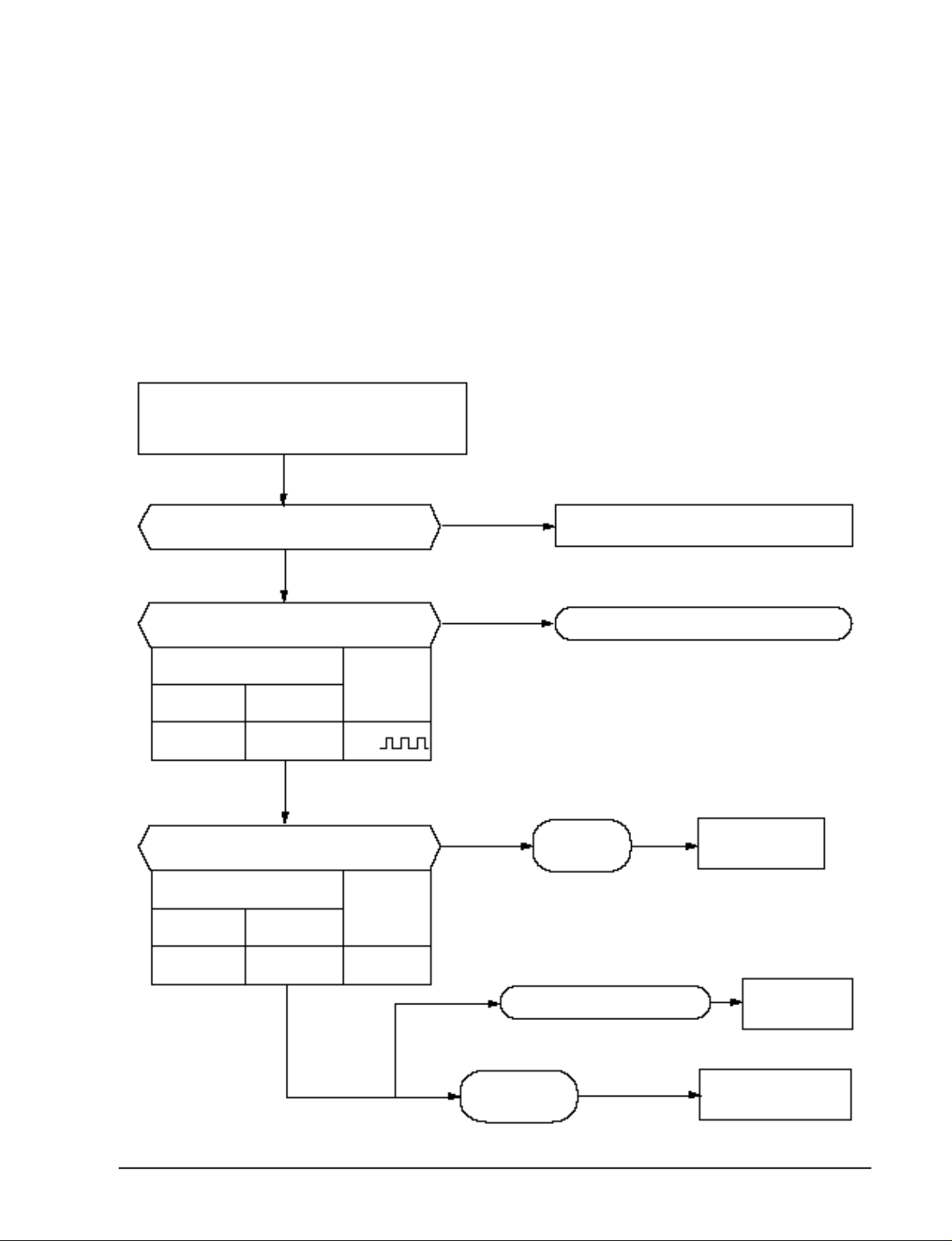
5-2-2 When the Indoor Unit Fan Does Not Operate. (Initial Diagnosis)
1) Checklist :
(1) Is the indoor unit fan motor properly connected with the connector (CN72)?
(2) Is the AC voltage corre c t ?
(3) Is HALL IC in indoor fan motor properly connected with the connector (CN42)?
(4) Is the running capacitor ( C R 7 1 ) p roperly connected with PCB board ?
2 ) Troubleshooting pro c e d u re
Troubleshooting
After unplugging out the power cord should
Does the Solid State Relay(SS71) work
properly?
+
SS71- SS71- 12V
be reconnected within five seconds.
YES
Does the STD lamp(Green) blink?
YES
Test rod location
-
YES
Is the supply voltage of the fan
motor sufficient?
Normal
Voltage
NO
NO
NO
Check as in the procedur “NO power parts” Refer tp
Microcomputer is out of order.
PCB is
out of order.
page 5-2.
PCB should be
replaced.
Test rod location
PCB CN72 Condition
pin #3 and #5
Samsung Electronics
Normal
voltage
Fan operate about AC 180V
YES
Fan motor
is out of order.
MF-C is out of order
Replace MFC
Fan motor
should be replaced.
5-3
Troubleshooting
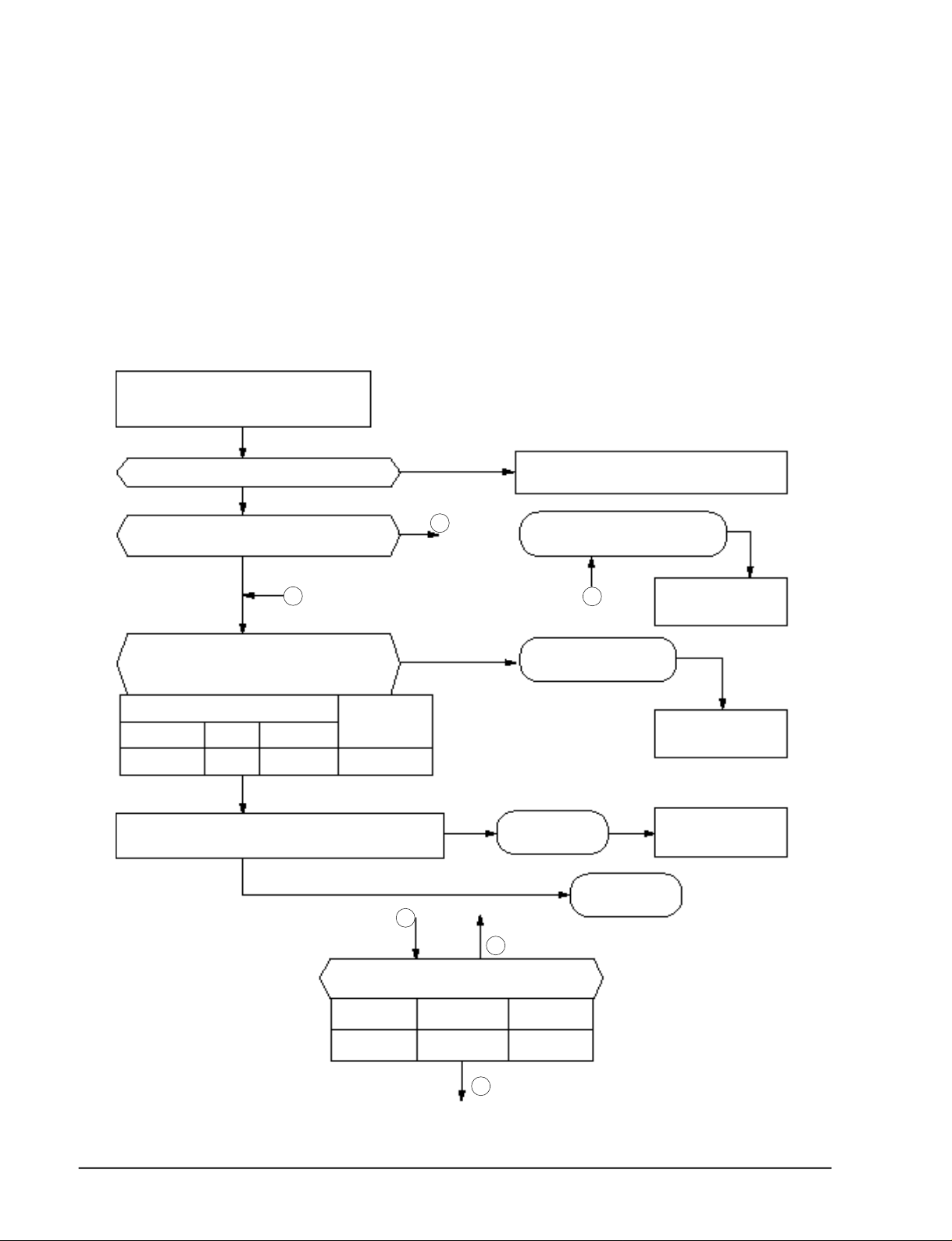
5-2-3 When the Outdoor Unit Does Not Operate. (Initial Diagnosis)
1 ) Checklist :
(1) Is input voltage normal?
(2) Is the set temperature of the remote control higher than room temperature in COOL m o d e ?
(3) Is the set temperature of the remote control lower than room temperature in HEAT mode?
(4) Is the POWER IN connector (CN71) linked corre c t l y ?
(5) Is the outdoor unit properly connected with the TERMINAL BLOCK connector((N1), 1, 2, 3)?
2 ) Troubleshooting pro c e d u re
After unplugging out the power cord should be
reconnected within five seconds.
Does the STD lamp blink
YES
Does the timer lamp blink during operation ?
NO
3
Is the power relay RY71 operated by adjusting the room
temperature?
Test rod location Normal
+ - Condition Voltage
IC4 Pin No.62 GND RY71 ON DC 4.8V
NO
Is rating voltage ±10% range applied relay between Terminal block
NO(N1) and No. 1
YES
NO
YES
NO
1
YES
Check as in the procedure "No Power parts"
1
NO
2
Room temperature sensor is
Microcomputer is
Power relay is
out of order
Refer to page 5-2.
out of order
2
out of order.
Outdoor unit is
out of order.
PCB should be checked.
PCB should be
checked.
Power relay should be
replaced.
5-4
Is the room sensor normal register?
10°C 20°C 30°C
17.96k Ω 12.09k Ω 8.3k Ω
YES
3
Samsung Electronics
 Loading...