

SAMSUNG APH450PG0K Service Manual
PACKAGED AIR CONDITIONER
A P H 4 5 0 P G
SERVICE
Manual
CONTENTSAIR CONDITIONER
1. Pre c a u t i o n s
2. Product Specifications
3. Operating Instructions and
I n s t a l l a t i o n
4. Disassembly and Reassembly
5. Tro u b l e s h o o t i n g
6. Exploded Views and Parts List
7. Block Diagrams
8. PCB Diagrams
9. Wiring Diagrams
10. Schematic Diagrams

© Samsung Electronics Co., Ltd. MAY. 1998.
Printed in Korea.
Code No. DB81-10147A(1)
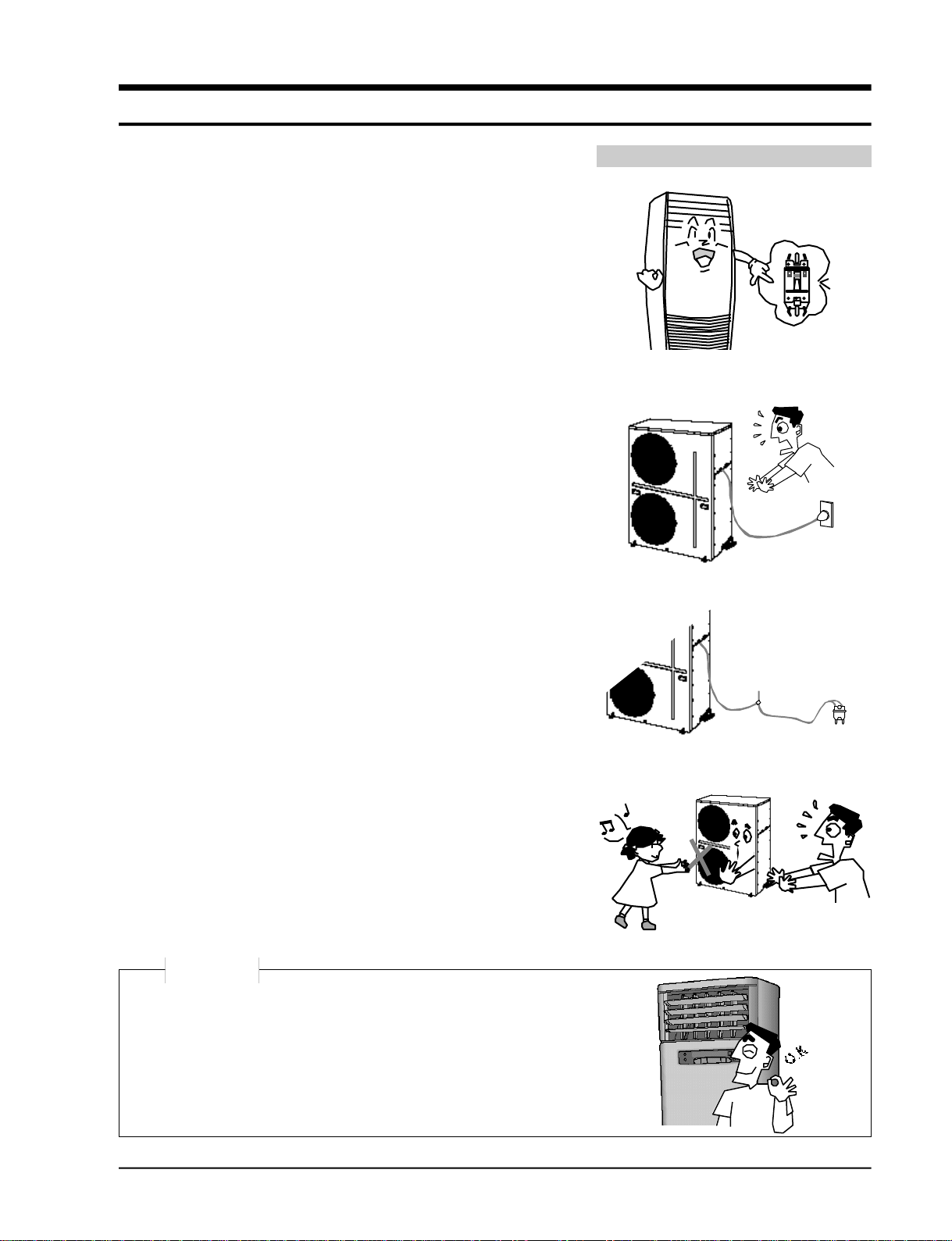
1. Precautions
1) Turn off the the power.
Be sure to turn off the power before attempting to repair the
unit such as the disassembly of the unit.
2) Be careful of electric shock
When checking the circuit with the power connected in
unavoidable circumstances, take special care not to touch the
live parts. There is a danger of electric shock.
3) Use of appropriate parts
Be sure to use the genuine parts of the relevant model when it
is necessary to replace parts. (Replace parts instead of repairing with regard to the malfunctioning of electric contact areas.
Never attempt to modify the unit. It is extremely dangerous
for the consumer to attempt to repair the unit on his(her)
own.)
4) Use of proper tools
Use appropriate tools for repair, and use measuring equipment after accurate calibration. Using worn tools may result
in problems, including poor contact and poor connection.
5) Avoid damage to electric wire or electric cord.
Check the electric cord or electric wire for any damage during
repair.
Be sure to replace it if damaged.
6) Avoid intermediate connection of the electric cord.
Never attempt to make an intermediate connection by cutting
the middle area of the electric cord or make a connection to
the power receptacle as it is very dangerous, causing problems
or fire.
7) Checking of insulation
Be sure to check the insulation resistance after completion of
the assembly work.
(Check whether the insulation resistance of the electric wire
and grounding terminal is over 30MΩ by using the insulation
resistance tester, and then connect the power source.)
8) Checking of grounding
Check the grounding condition, and perform repair if poorly
grounded.
9) Checking of installation condition
Check the installation condition of the unit, and perform
repair if there is any defective area.
If the unit remains in an unstable installing condition, install it
at a new site.
10) Be careful of children
As the repair of the unit involves a lot of dangerous elements,
do not allow children to approach nearby during repair work.
Turn off the sub power switch separately installed.
No connection with the power receptacle
Cleaning
Upon completion of the repair, clean the air
conditioner and surrounding area, and
inform the customer of completion of the repair.
Samsung Electronics
1-1

M E M O
1-2
Samsung Electronics
2. Product Specifications
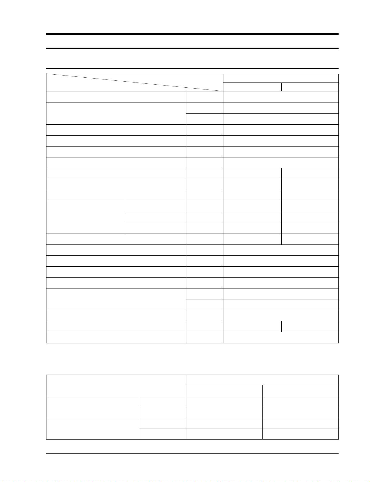
2-1 Table
Model APH450PG
ITEM Indoor unit Outdoor unit
Power source
Capacity
(Cooling/Heating)
Aux. heater
Power consumption
E.E.R (Cooling/Heating)
Running current (C/H)
Noise level (C/H)
Moisture removal
Air circulation
Dimension Width
(Net/Packed) Height
Depth
Weight(Net/Packed)
Piping box
Refrigerant type
Refrigerant quantity
ø/V/Hz
kcal/h
BTU/h
Watt/h
W
kcal/Wh
A
dBA
l/hr
m3/h
mm
mm
mm
kg
kg
3 / 380 / 50
11,250 / 12,200
45,000 / 48,800
3,000
5,000 / 4,700
2.25 / 2.60
9 / 8.7
53 / 54 63
5.8
1,920 4,800
590 / 704 930 / 1,200
1,810 / 1,925 1,240 / 1,370
420 / 600 385 / 540
75 / 85 123 / 133
14
R-22
4.8
Compressor type
Protective device
Refrigerant piping size
Drain piping size
Loading Q’ty (20’/40’)
Note: (1) The data are measured at the following conditions.
Indoor air temperature DB
WB
Outdoor air temperature DB
WB
Samsung Electronics
Reciprocating
Internal thermostat (CM)
High pressure switch
inch
mm
set
Cooling Heating
27.0˚C(80.6˚F) 20.0˚C(68.0˚F)
19.0˚C(66.2˚F) 12.0˚C(53.6˚F)
35.0˚C(95.0˚F) 7.0˚C(44.6˚F)
24.0˚C(75.2˚F) 6.0˚C(42.8˚F)
Gas : 3/4”, Liquid : 3/8”
I.D 18 I.D 16
12 / 24
APH450PG
2-1
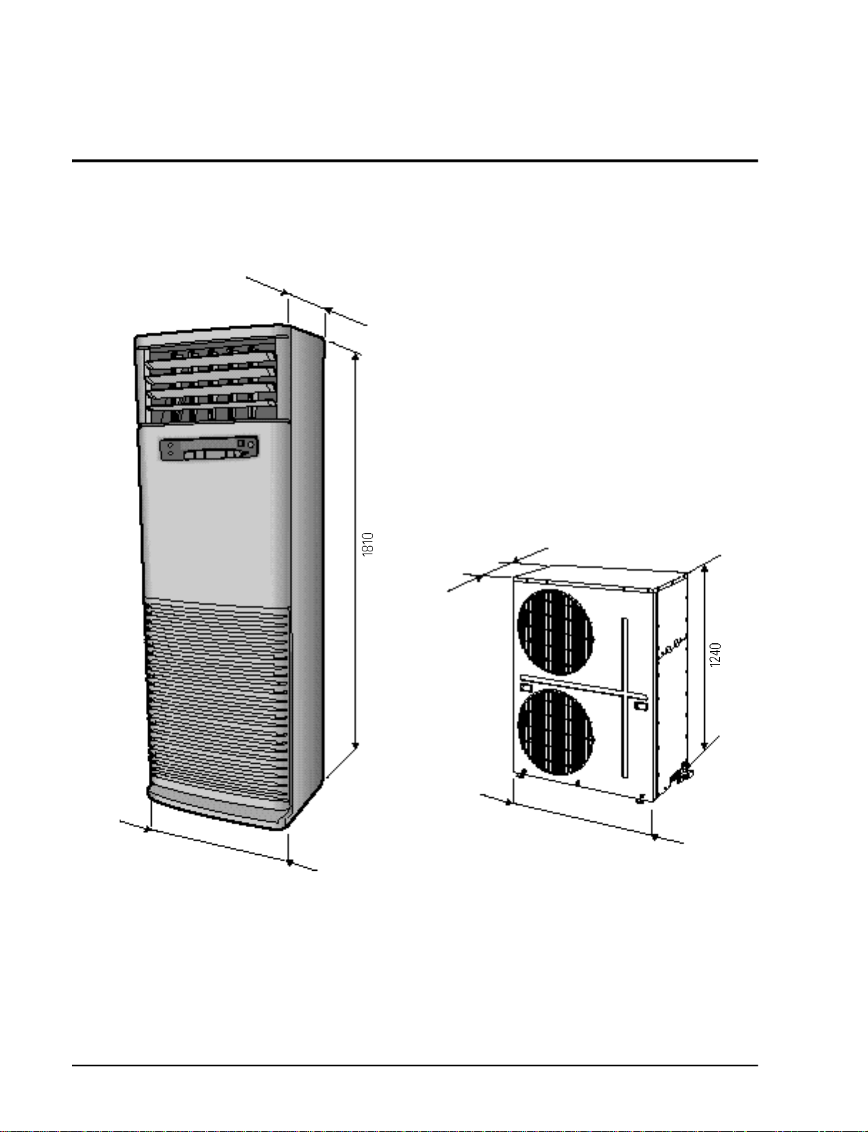
2-2 Dimensions
420
Unit : mm
385
2-2
930
590
Samsung Electronics
3. Operating instructions and Installation
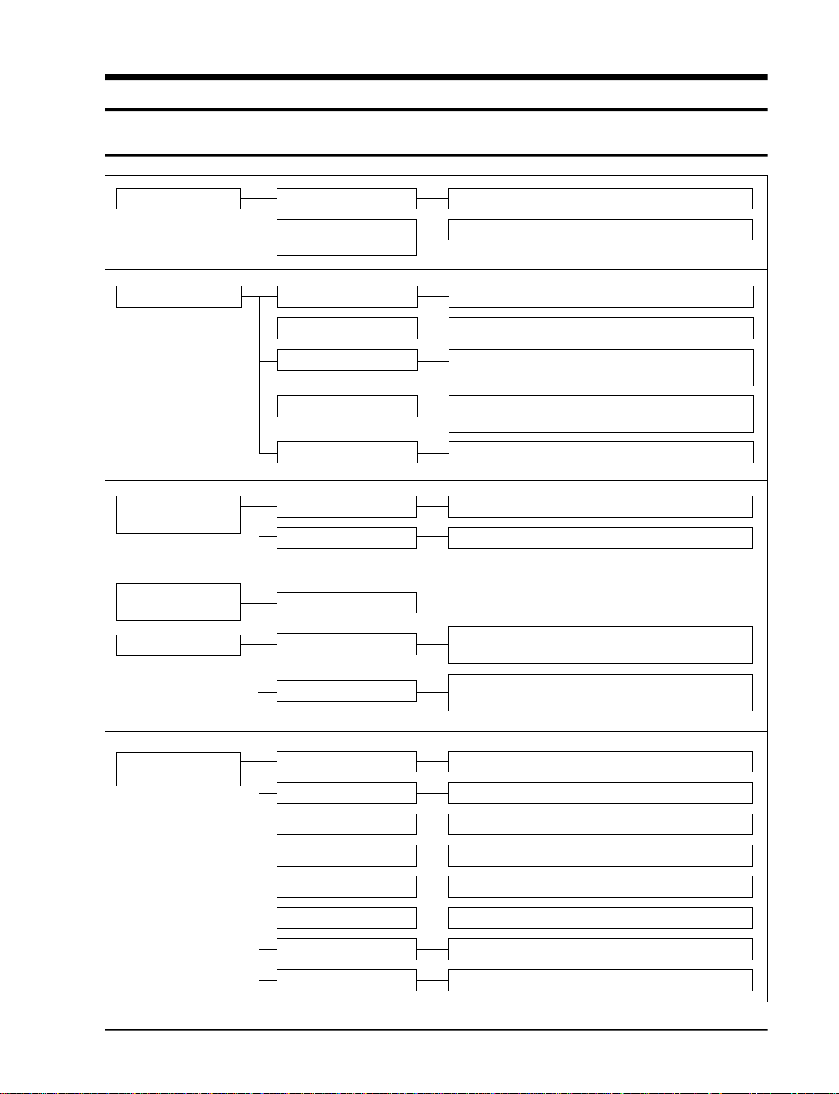
3-1 Operating Instructions
Operation Main switch operation
Operation of remote
controller
Function selection Auto cool mode
Auto heat mode C o n t rol of fan motor step according to current temperature
Cool mode
Heat mode
Fan mode
Fan speed
selector mode
Airflow selector
mode
Manual 3-step
Auto
Left-right turn
Operation of auto cool, auto heat, cool, heat, fan
Operation of turbo, cool, heat, fan
C o n t rol of fan motor step according to current temperature
C o n t rol of cool according to the diff e rence between curre n t
and desired temperature
C o n t rol of cool according to the diff e rence between curre n t
and desired temperature
Operation of indoor fan motor only
High, medium, low
C o n t rol of fan motor step according to current temperature
Convenience function
LED display
function
Turbo operation
Convenience reservation
Function selector
Selection of fan speed Low, medium, high lamp
Selection of airflow Left-right lamp
Current temperature Indoor temperature display
Desired temperature Desired temperature display
Fan speed diagram Low, medium, high, turbo lamp
Convenience reservation Reserve lamp and reserve time display
Current time Current time display
Turbo-operating compressor and powerful operating fan
m o t o r ( 3 0 m i n u t e s )
R e s e rve function which is off after on time of 1, 2, 3, 4, or 5
h o u r s
Auto cool, auto heat, cool, heat, turbo, fan lamp
Samsung Electronics
3-1
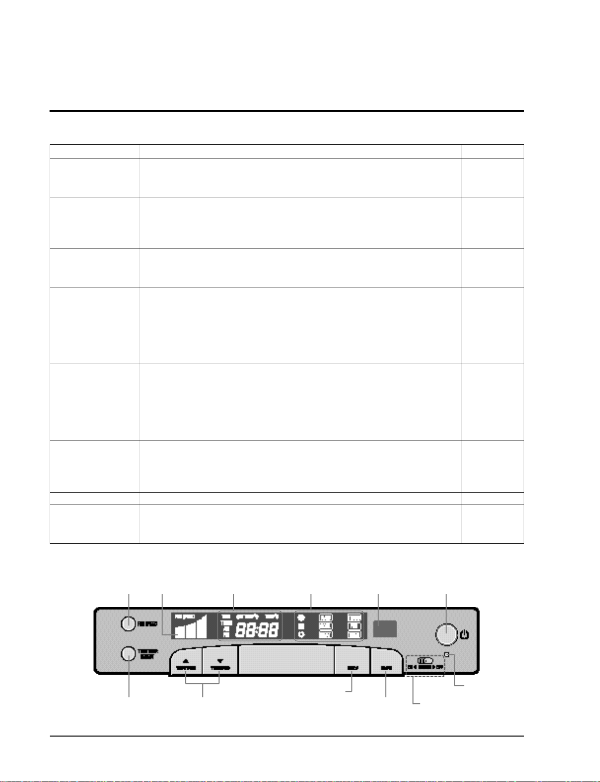
3-2 Key type and functions
3-2-1 PANEL key type and functions
Key name Key operating function Key type
On/off Start and end of operation TACT
- ON 1 time = operation start, ON again = operation end.
- No continued operation
Mode selection Change of the operation mode TACT
- Each time the button is pressed(ON), the mode is changed in the following order:
“auto → cool → fan”(standard=auto)
- No continued operation
Fan speed Setting of the indoor fan motor speed TACT
selection - Each time the button is pressed ON, the mode is changed in the following order:
“low → medium → high”(standard=high)
Temperature(time) Increase the desired temperature(current time) TACT
setting(up) - Temperature: When pressing the button(ON) one time,
the desired temperature is increased by the unit of 1°C.(18°C- 30°C)
- Time: When pressing the button(ON) one time, the time is increased by 1 minte.
If the “on” button is pressed continuously, the time is increased by 10 minutes.
- One short, and continued operation
Temperature(time) Decrease the desired temperature (current time) TACT
setting(down) - Temperature: When pressing the button(ON) one time,
the desired temperature is decreased by the unit of 1°C. (18°C - 30°C)
- Time: When pressing the button(ON) one time, the time is decreased by 1 minute.
If the “on” button is pressed continuously, the time is decreased by 10 minutes.
- One short, and continued operation
Change of display The temperature and current time can be changed. TACT
- If the “on” key is pressed 1 time, current temperature
and desired temperature are displayed.
- If the “on” key is pressed 1 time, current time is displayed.
Brief reservation The hours of 1,2,3,4 and 5 is selected whenever one time of on is performed. TACT
Heater on/off selection If the switch is selected to the on direction, the heater is operating at the heater SLIDE
operation condition.
The heater is not operating when the switch is selected to the off position.
* Operating functions
Fan Speed
adjustment
Time/Temperature
Selection
3-2
Fan Speed
display
Time/Temperature
display
Time or Temperature
adjustment
Operating Light
Operating
Mode Selection
Remote control
Sensor
Timer
adjustment
On/Off Button
Power Light
Auxiliary Heater
Switch (option)
Samsung Electronics
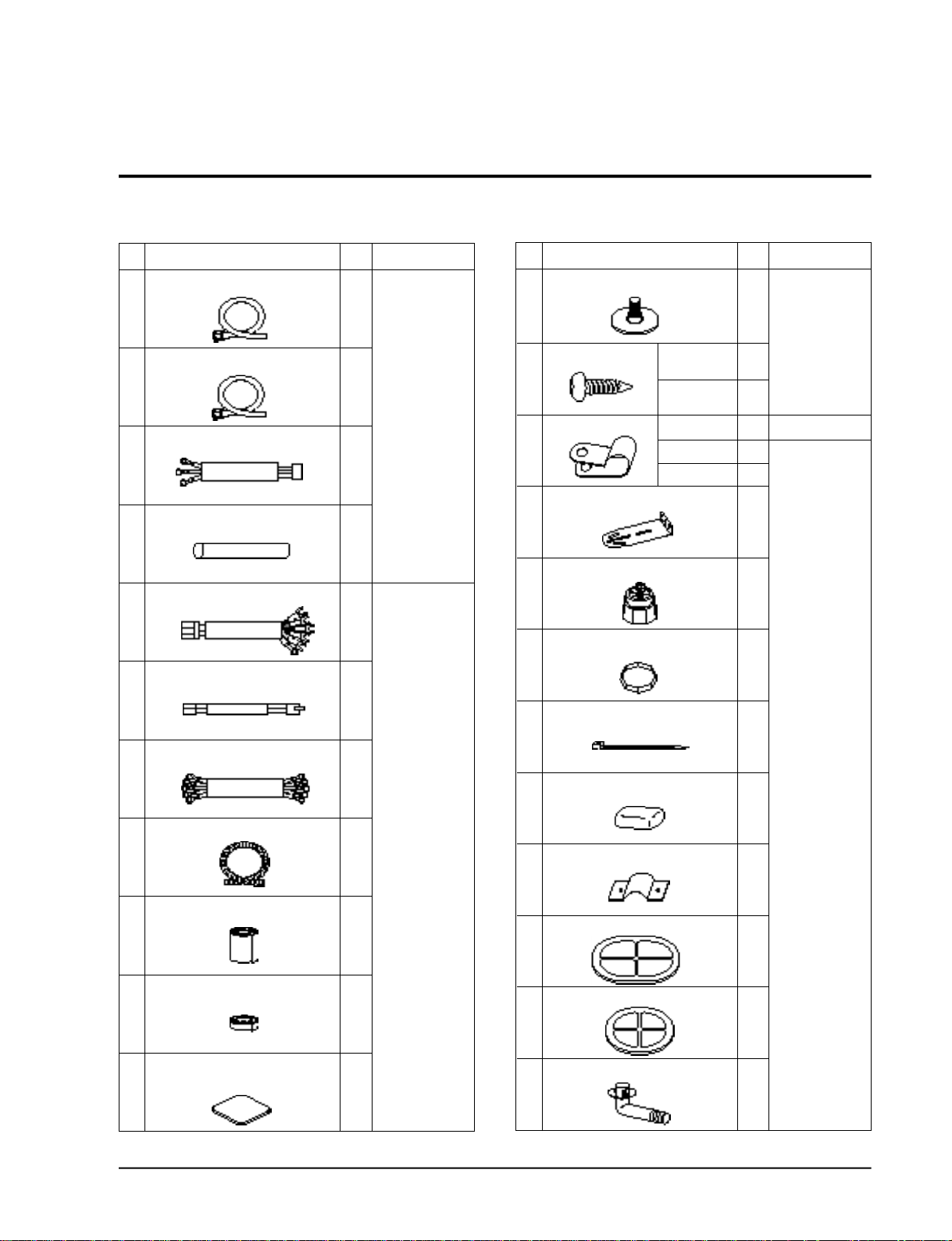
3-3 Accessory Parts List
3-3-1 Connection Parts 3-3-2 Others
No.
Connecting pipe
1
Connecting pipe
2
Heater cable (3 strand)
3
Protection tube
4
Connecting wire (7 strand)
5
Wire of sensor (2 strand)
6
Power cable
7
Drain hose
8
Finishing tape
9
Part Name Q’ty Remarks
3/8”
(ø9.52mm)
3/4”
(ø19.05mm)
1
1
1
1
1
1
1
1
2
Option
(Piping box)
Piping box
No.
Leg holder for indoor unit
1
Screw
2
Cable clamp
3
Indoor unit fixing holder
4 1
Leg holder for outdoor unit
5
Insulation rubber bottom
6
Cable tie
7
Putty
8
Pipe band
9
Rubber cabi slot
10
Part Name Q’ty Remarks
TH M4 X 12
TH M4 X 25
12N
8N
6N
4
Piping box
4
4
2
Option(Piping box)
3
1
4
4
5
Piping box
3
3
1
Insulation tape
10
Insulation tube for indoor
unit piping connection
11
Samsung Electronics
1
1
Rubber cabi hole
11
Drain plug out
12 1
1
3-3
3-4 Installation
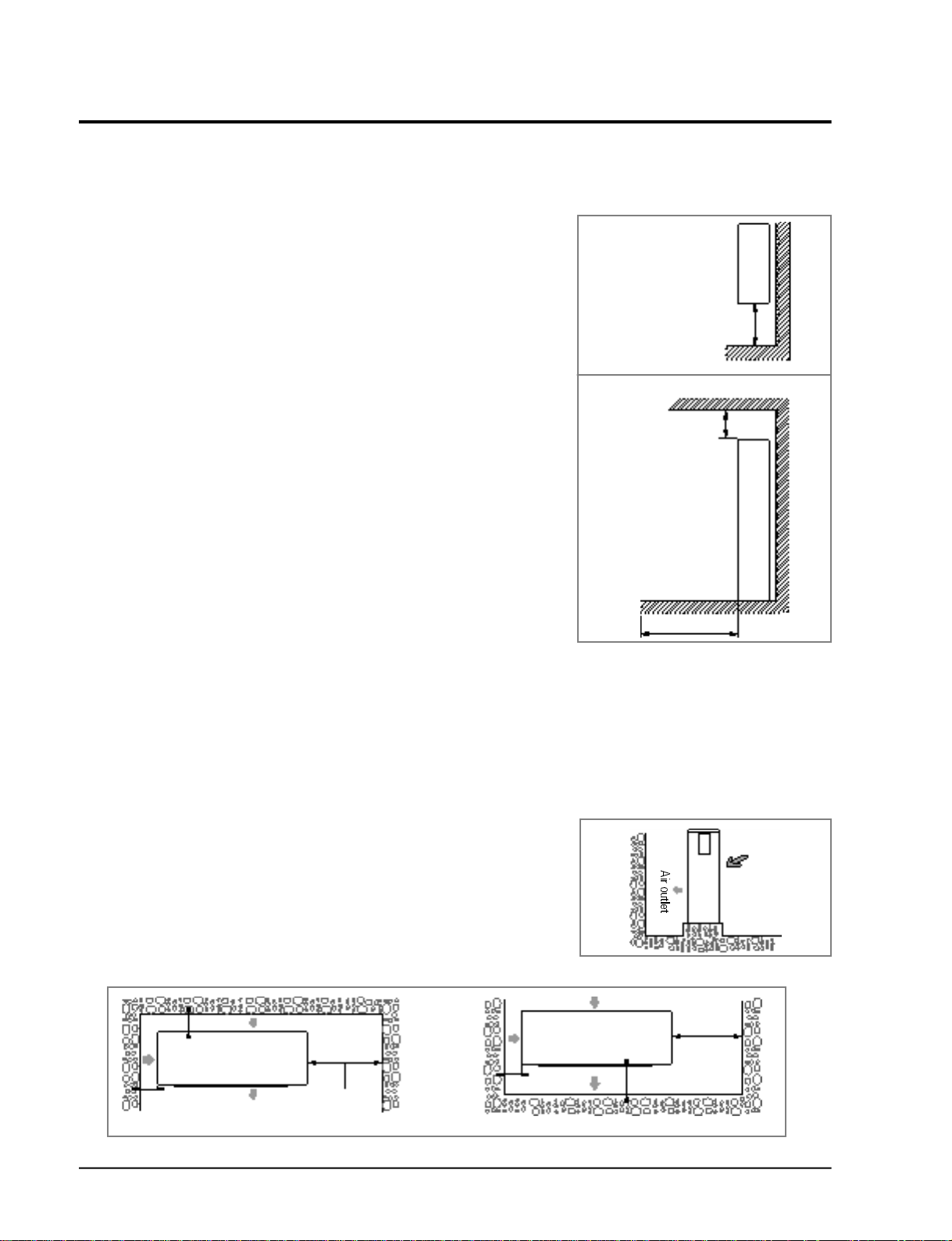
3-4-1 Selection of Installation Place
3-4-1(a) Indoor Unit
• Install the unit at a place close to the wall facing the outside
as it is necessary to perform piping connection with the out-
Top view
door unit.
- It is effective to install the unit at a window side to ensure
uniform distribution of indoor temperature .
• Install the unit at a place where there is no obstacle against
the wind around the air inlet and air outlet.
Above 50cm
• Install the unit horizontally at a stable, rigid place.
(When installing the unit at a place subjected to vibration,
noise may occur. )
• Avoid a place near the door which is frequented by people.
• Avoid a place subject to direct sunlight.
Side view
Above 20cm
3-4-1(b) Outdoor Unit
• Place free from the risk of combustible gas leakage.
• Place which can bear the weight of the unit.
• Place which can bear the fixing strength of the outdoor unit.
• Avoid a place subject to oil (including machine oil).
• Avoid a saline place.
• Avoid a place subject to sulfide gas (hot spring zone).
(When installing the unit at such special environmental
conditions, it may cause machine trouble. When it is
unavoidable to use such places. It re q u i res special
m a i n t e n a n c e . )
• A place where the discharge air and noise of the outdoor unit do not disturb the neighborh o o d .
(Take special care not to cause any inconvenience to your neighbors when installing the unit on
the borderline with your neighborh o o d . )
• A place where strong wind does not head against the air outlet of the outdoor unit.
(If a strong wind heads directly against the air outlet at the time of cool operation, a safety device
can be operated.)
• Do not install the outdoor unit at an unstable place such as outer wall of an apartment or building.
The outdoor unit may fall down, causing severe personal or property damage or loss.
Above 100cm
* If there is any unavoidable reason to install the unit at such
a place, take the following measures against the wind;
1. When installing the unit at a roadside concentrated with
buildings, install it parallel with the ro a d .
Wall
2. Install the unit so that the air outlet faces toward the wall
at a place such as rooftop, which may be subjected to
s t rong wind.
* The outdoor unit should be installed in accordance with the service space.
Above 15cm
Above 50cm
Above 15cm
Space for piping
and wiring
The air inlet faces toward the wall.
Above 15cm
The air outlet faces toward the wall.
3-4
Strong wind
Roof top
Above 50cm
Space for piping
and wiring
Above 30cm
Samsung Electronics
Operating instructions and Installation
3-4-2 Electrical Work
The electrical work should be performed by a specialist qualified for the work.
• Use the three phase power supply, and be sure to install the sub power distributing board for
exclusive use with the unit(separately purchased by the user).
* Avoid octopus-type wiring as it can cause a drop in voltage, thus resulting in poor performance
of the automatic control circ u i t .
• Be sure to install circuit breaker (separately purchased by the user).
• Be sure to connect the grounding wire .
Electric power spec
Power
Ampere of breaker
Knife switch
Switch
Fuse
Size of grounding wire
Min. size of electric wires from/to
the indoor/outdoor unit
3phase 4wires 380V
50 A
25A
25 A
2
2.5 mm
0.75 mm
2
CAUTION
• Be sure to use the wires, and switches or fuses of power distribution board are qualified and fulfill the specification.
• Be sure to install knife switch or circuit breaker on the power distribution board.
• The electrical and grounding work should be performed as per “ technical specification of electrical facilities ” and “
specification of internal wiring ”.
• Be sure to connect main electrical input wires with
bolted connectors using compressed terminal.
Applicable voltage 380V
342V ~ 418V
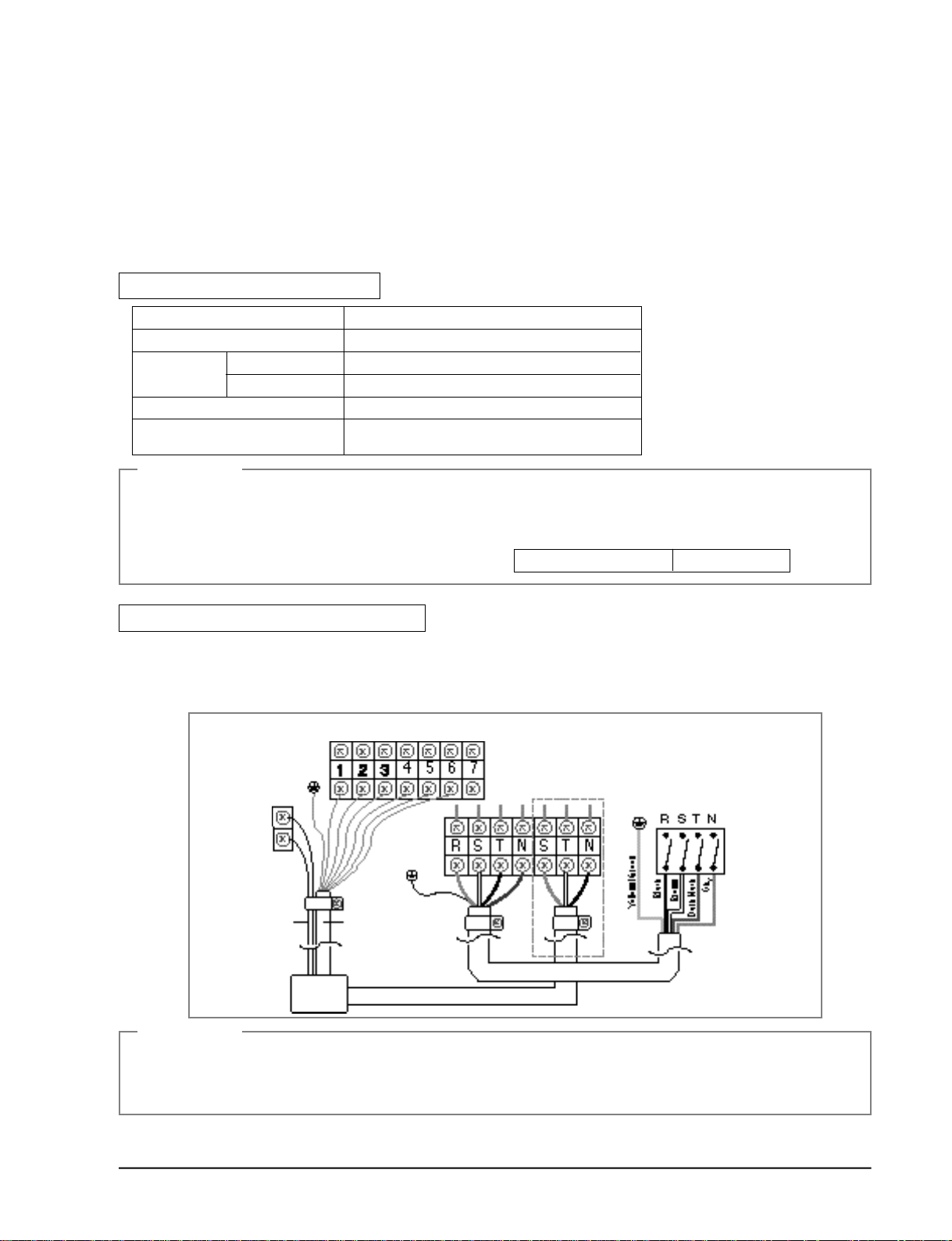
When connecting 3Phase 4wires 380V AC
1. Remove cover of electric box on side panel of outdoor unit.
2. Connect electric input wires (R,S,T,N) to each terminal (R,S,T,N) of the electric box on outdoor
unit re s p e c t i v e l y.
3 . Connect electric wires to each terminal on indoor and outdoor unit re s p e c t i v e l y.
OUTDOOR SIDE
1:Thin Brown
2:Sky
3:Brown
4:Black
5:Thin sky
6:Dark Black
Wire of sensor
Indoor/outdoor unit
connecting wire
Inoor
unit
Heater cable
Power cable
CAUTION
• Be sure to connect electrical wires correctly, if not it can cause a trouble.
* Be sure to fix wires from/to the indoor and outdoor unit on the piping insulated.
Avoid wires contact to bare pipe or valve directly without any insulated spacer.
* Must be use the approval wire according to IEC or EN requirement.
Samsung Electronics
Knife switch or
automatic circuit
breaker
3-5
Operating instructions and Installation
3-4-3 Installation Method
3-4-3(a) Installation Procedures
1 . Open the inlet grille, and remove the flare nut.
2. Bend the connection pipe to an appropriate length using the spring bender depending
upon the installation place.
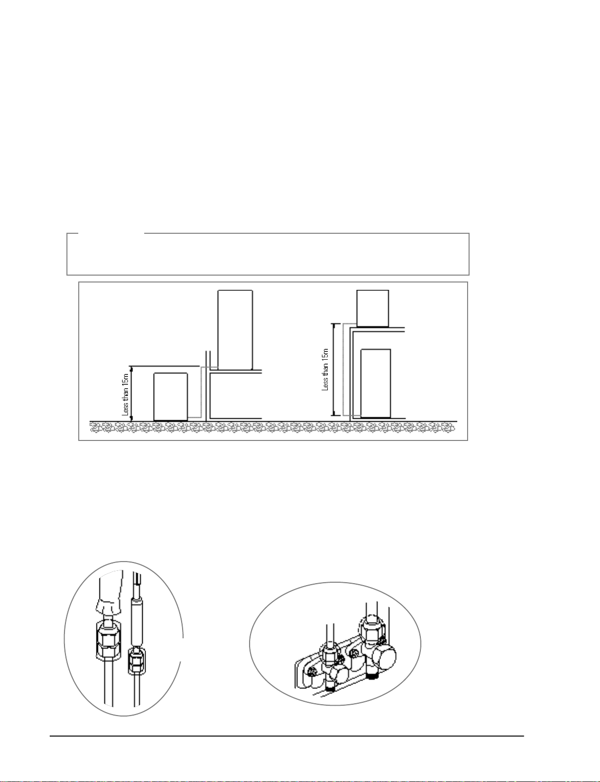
- Allowable pipe length : Maximum 25m
- Allowable pipe drop distance : Maximum 15m
- Make no more than ten bending points on the pipe
• When the pipe length is in excess of the standard pipe length of 5m, add the refrigerant
(R-22) of 50g for each additional 1m.
CAUTION
• If the pipe is lengthened, the performance of the unit is degraded, and the service life is shortened.
Therefore, the pipe length should be as short as possible (less then 15m).
Outdoor
unit
Indoor
unit
Indoor
Outdoor
unit
3. Install the high pre s s u re pipe to the heat exchanger liquid pipe, and the low pre s s u re pipe to the
heat exchanger gas pipe respectively using the flare nut, taking care not to cause any leakage of
re f r i g e r a n t .
4. Be sure to insulate the pipe with appropriate insulation material.
5. Insert the drain hose into the drain pipe, and connect them by tying them to the cable tie to prevent any water leakage.
6. After completion of the installation, check the connecting area for any gas leakage.
7. Wind a finish tape when the wiring of the refrigerant pipe, the unit, and the drain piping are comp l e t e d .
Outdoor unit
checking area
Indoor unit
checking area
unit
3-6
Samsung Electronics
Operating instructions and Installation
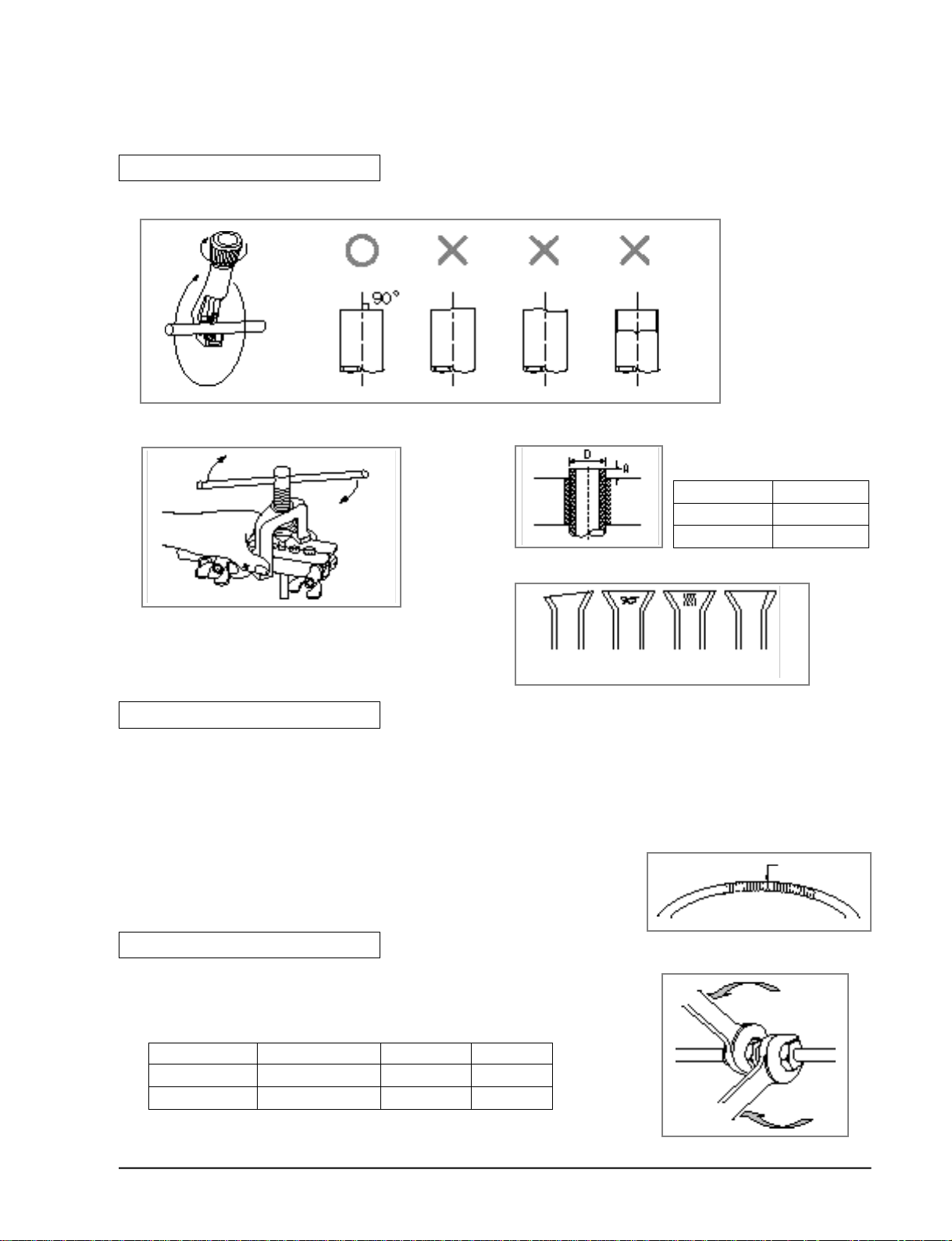
3-4-3(b) Connection of Refrigerant Piping
Flare Processing
1. Cut the pipe using the pipe cutter.
Oblique Roughness Burr
2. Insert the flare nut into the pipe, and then perform the flare pro c e s s i n g .
Outer Diameter
ø 9.52mm
ø 19.05 mm
A ( out / in)
1.7 / 1.0 (mm)
2.2 / 1.5 (mm)
• Unproper flaring
Inclined Surface
damaged
Cracked Uneven
thickness
Pipe Bending
1. Perform bending of the pipe using the bender which has a specified bending radius.
2. Be sure to take full care to perform bending of the pipe successfully at one time.
Bending and unbending the pipe more than twice makes the bending work increasingly diff i c u l t .
3. You may use the spring inserted into the gas pipe instead of the bender to bend the pipe.
4. When you bend the pipe using the spring, hold the pipe with both hands to prevent any distortion, and secure a minimum bending radius of more than 100mm.
Spring
Tightening of Connection Parts
• Align the center of the connection piping, and tighten the flare nut
by turning it with hand. Then tighten it again using the spanner in
the direction as shown in the figure .
ø 9.52mm
ø 19.05mm
Tightening Torque
400 kg • cm
700kg • cm
Final Torque
450 kg • cm
750kg • cm
RemarksOuter Diameter
Samsung Electronics
3-7
Operating instructions and Installation
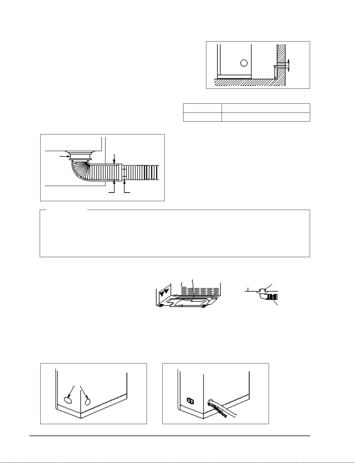
3-4-3(c) Drilling a Hole in the Wall
• Drill a hole of 70mm in diameter to the outside.
• The drilling should be done at a distance of less
than 150mm from the floor facing the indoor unit.
3-4-3(d) Drain Hose
Less than
ø70mm
150mm
• Extend the drain hose to the drain hose connected
to the drain pan, and fix it with the tape or a cable
tie to prevent separation. Then make a covering of
Piping Material
Insulator
it so that water can not flow outward l y.
Drain pan
Band
Drain hose
Insulation
Indoor and
outdoor
connection
CAUTION
1. As the draining is of natural drain type, make the drain hose direct downward.
2. If there is any foreign substance in the drain plate, it may clog the drain pipe.
Therefore, be sure to remove the foreign substance inside after installation.
3. After completion of installation, be sure to pour water into the drain pan, and then check the draining condition.
(There is no problem in draining when the draining is completed within 20 seconds.)
• In heating and deice operation, condensed water may be generated.
Install drain line as following procedure.
Hole
1. Insert the drain plug into base hole.
2. And then connect drain hose to drin plug.
Vinyl Chloride(Outer diameter ø 16mm)
Foamed Polyethylene
Base
Drain plug
3-4-3(e) Rat-prevention Cover
• The piping of this unit can be connected to the left and rear side.
• When you hit the area for piping connection slightly with a hammer, a hole is made.
- If there is any reason to change connection, fill in hole with ruber cabi slot.
Holes for piping
connection (2 points)
3-8
Samsung Electronics
Drain hose
Operating instructions and Installation
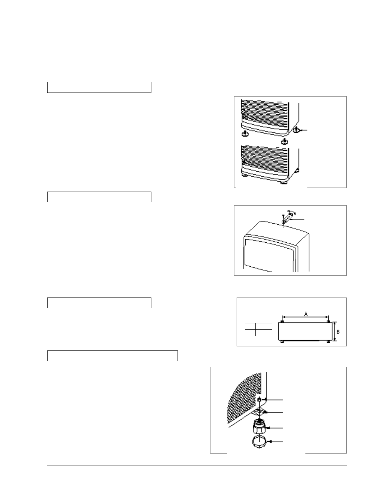
3-4-3(f) Indoor Unit
In order to install drain hose through wall, adjust height (max. 150mm) of the indoor unit using
leg holder.
Fixing to the floor
• When using the leg holder of the indoor unit.
1. Lie down the unit on flat floor.
2 . Insert the leg holders into screwed holes and then
fasten them clockwise.
3 . Turn the unit right and adjust horizontal line of it.
* Mis-alignment of the unit can cause vibration and
Leg holder of
the indoor unit
n o i s e .
Fixing to the wall
• When using fixing holder of the indoor unit.
1 . Fix the holder using long screw bolts on wall.
2 . Fix the unit using two screw bolts or four anchor
bolts.
(Size of the screw hole on the holder is ø4.5mm
and size of the bolt is ø6mm.)
3-4-3(g) Outdoor Unit
When using the anchor bolt
1 . Fix the unit on a flat, rigid floor using the anchor bolt.
(Anchor bolt : M10 x 4 points - separately purc h a s e d )
When using the leg holder of the outdoor unit
1 . Insert the foot holder (4EA).
2 . Remove the nut fastened to the leg holder,
and then insert the leg holder into the hole of
the outdoor unit leg.
3 . Fix the unit securely with the nut.
Fixing holder of the
indoor unit
Anchor bolt fixing dimensions
Unit:mm
A 840
B 415
Nut
Samsung Electronics
Outdoor unit leg
Leg holder
Foot holder
3-9
Operating instructions and Installation
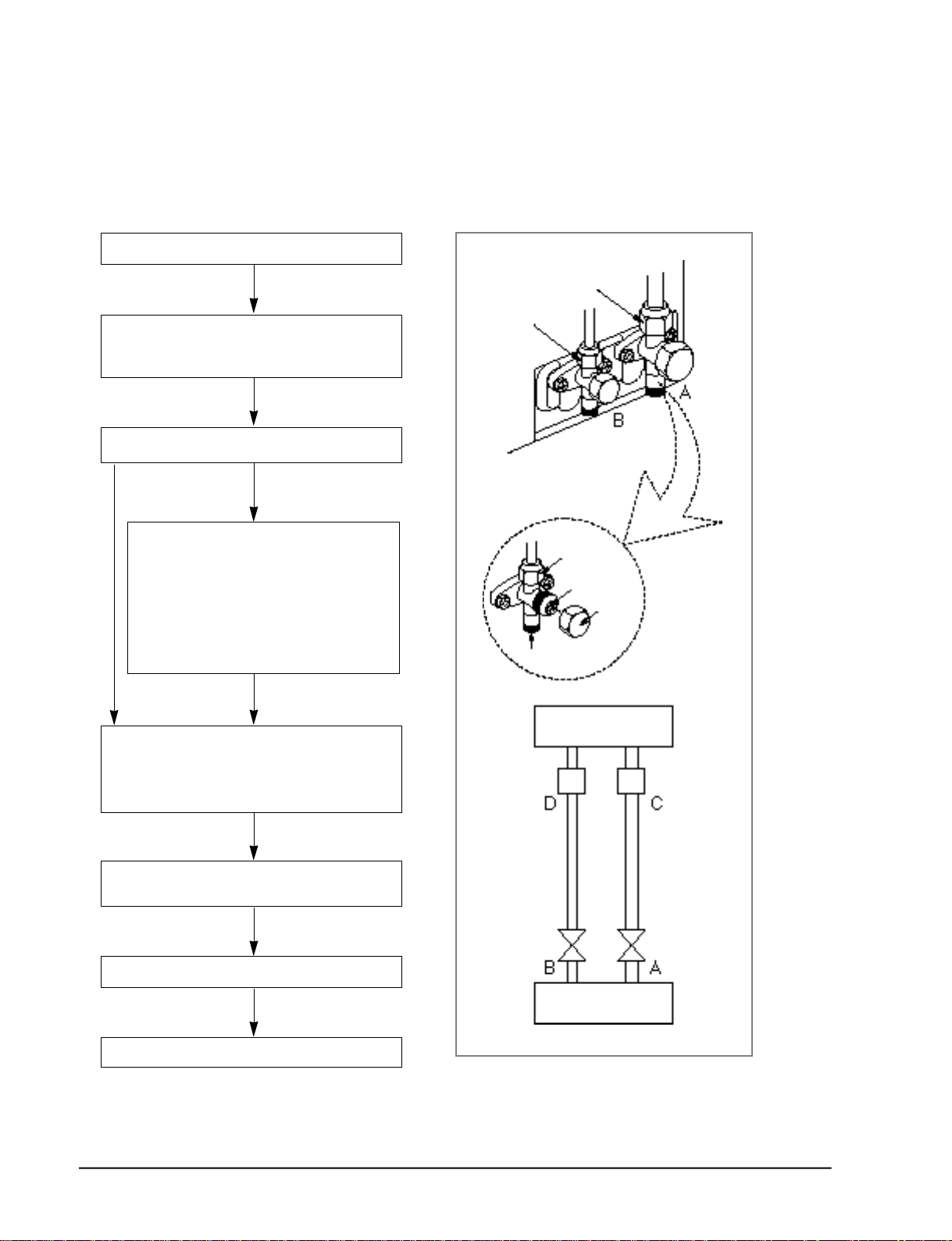
3-4-3(h) Air Purge
• Be sure to perform the air purge of the indoor unit, and piping using the refrigerant of the outdoor unit at the time of installation.
Open the cap of the valve(B), and valve(A).
Open the valve cock of the valve(B) by
approximately 45°. After an elapse
of 10 seconds, close the valve cork.
Check the connection piping for leakage.
Not
Leaking
Ieaking
• Close the nut for the connection piping
again.
Proceed to h when there is no leakage.
• If it is necessary to perform repair due to
continuous leakage of gas, discharge the
refrigerant gas, and repair the leaking area.
Then revacuum and refill the refrigerant.
OUTDOOR UNIT
Gas side
Liquid side
Flare nut
Valve cock
Cap
Needle valve cap
* Open the needle cap of the valve(A), and press
the needle valve for 3 seconds to drain the gas
out.
Repeat this procedure three times.
Open the valve cock of valve(B) and
valve(A) completely.a
Close the cap of each valve.
Check the valve for leakage.
Indoor unit
Liquid side Gas side
3-Way valve
Outdoor unit
3-Way valve
3-10
Samsung Electronics
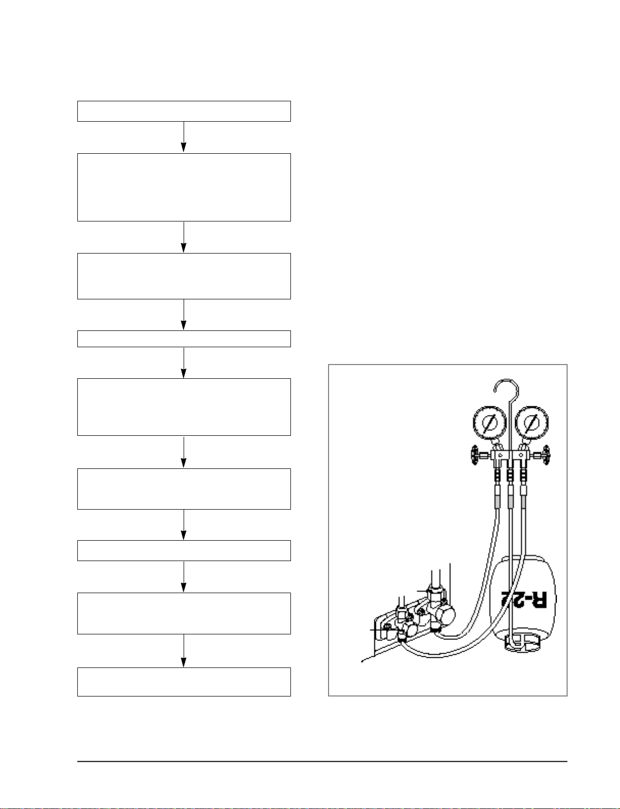
3-4-3(i) Refrigerant Charging
Air purge(at the time of new installation only)
Close the gas pipe side valve by turning it
clockwise.
Connect the pressure gauge to the low
pressure side service valve, and then open
the gas pipe side valve again.
Connect it to the refrigerant filling tank.
(Turn the tank upside down : Fill the refrigerant
in liquid form.)
Operating instructions and Installation
Start cooling operation.
Check the pressure of the pressure gauge.
Check whether the low pressure side is within
the range of 4.5~5.5kg/cm2G
(outside temperature 35°C).
Open the tank and refill the refrigerant
until arriving at the proper pressure.
(Refill the refrigent slowly checking the pressure.)
Stop operation.
Close the gas pipe side valve, and loosen
the pressure gauge connected.
Then open the gas pipe side valve again.
OUTDOOR UNIT
Gas pipe side
Liquid
pipe side
Tighten the cap of each valve using
a specified tool.
Samsung Electronics
3-11
 Loading...