

3. Operating instructions and Installation
3-1 Operating Instructions
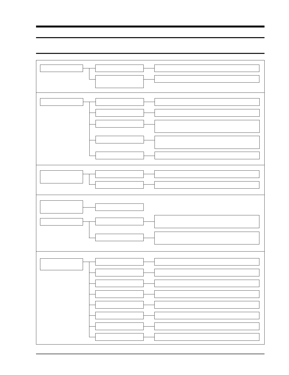
Operation Main switch operation
Operation of remote
controller
Function selection Auto cool mode
Auto heat mode C o n t rol of fan motor step according to current temperature
Cool mode
Heat mode
Fan mode
Fan speed
selector mode
Airflow selector
mode
Manual 3-step
Auto
Left-right turn
Operation of auto cool, auto heat, cool, heat, fan
Operation of turbo, cool, heat, fan
C o n t rol of fan motor step according to current temperature
C o n t rol of cool according to the diff e rence between curre n t
and desired temperature
C o n t rol of cool according to the diff e rence between curre n t
and desired temperature
Operation of indoor fan motor only
High, medium, low
C o n t rol of fan motor step according to current temperature
Convenience function
LED display
function
Turbo operation
Convenience reservation
Function selector
Selection of fan speed Low, medium, high lamp
Selection of airflow Left-right lamp
Current temperature Indoor temperature display
Desired temperature Desired temperature display
Fan speed diagram Low, medium, high, turbo lamp
Convenience reservation Reserve lamp and reserve time display
Current time Current time display
Turbo-operating compressor and powerful operating fan
m o t o r ( 3 0 m i n u t e s )
R e s e rve function which is off after on time of 1, 2, 3, 4, or 5
h o u r s
Auto cool, auto heat, cool, heat, turbo, fan lamp
Samsung Electronics
3-1
3-2 Key type and functions
3-2-1 PANEL key type and functions
Key name Key operating function Key type
On/off Start and end of operation TACT
- ON 1 time = operation start, ON again = operation end.
- No continued operation
Mode selection Change of the operation mode TACT
- Each time the button is pressed(ON), the mode is changed in the following order:
“auto → cool → fan”(standard=auto)
- No continued operation
Fan speed Setting of the indoor fan motor speed TACT
selection - Each time the button is pressed ON, the mode is changed in the following order:
“low → medium → high”(standard=high)
Temperature(time) Increase the desired temperature(current time) TACT
setting(up) - Temperature: When pressing the button(ON) one time,
the desired temperature is increased by the unit of 1°C.(18°C- 30°C)
- Time: When pressing the button(ON) one time, the time is increased by 1 minte.
If the “on” button is pressed continuously, the time is increased by 10 minutes.
- One short, and continued operation
Temperature(time) Decrease the desired temperature (current time) TACT
setting(down) - Temperature: When pressing the button(ON) one time,
the desired temperature is decreased by the unit of 1°C. (18°C - 30°C)
- Time: When pressing the button(ON) one time, the time is decreased by 1 minute.
If the “on” button is pressed continuously, the time is decreased by 10 minutes.
- One short, and continued operation
Change of display The temperature and current time can be changed. TACT
- If the “on” key is pressed 1 time, current temperature
and desired temperature are displayed.
- If the “on” key is pressed 1 time, current time is displayed.
Brief reservation The hours of 1,2,3,4 and 5 is selected whenever one time of on is performed. TACT
Heater on/off selection If the switch is selected to the on direction, the heater is operating at the heater SLIDE
operation condition.
The heater is not operating when the switch is selected to the off position.
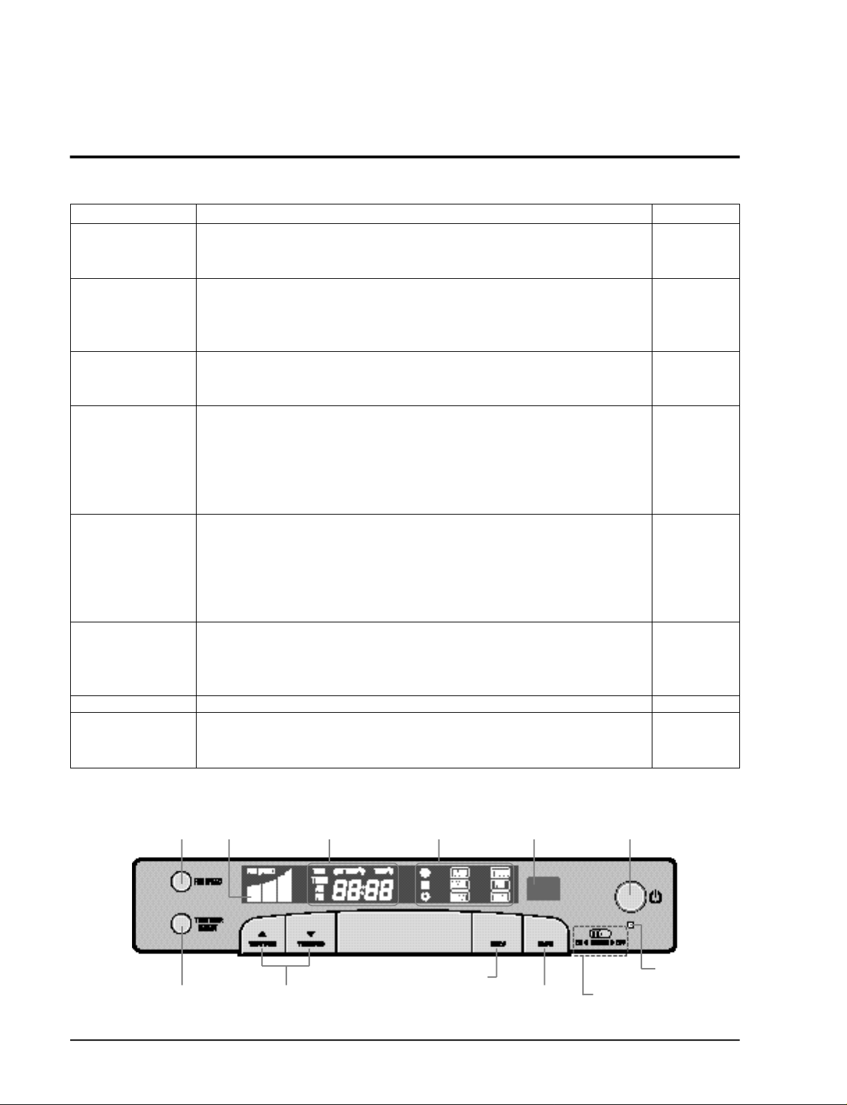
* Operating functions
Fan Speed
adjustment
Time/Temperature
Selection
3-2
Fan Speed
display
Time/Temperature
display
Time or Temperature
adjustment
Operating Light
Operating
Mode Selection
Remote control
Sensor
Timer
adjustment
On/Off Button
Power Light
Auxiliary Heater
Switch (option)
Samsung Electronics
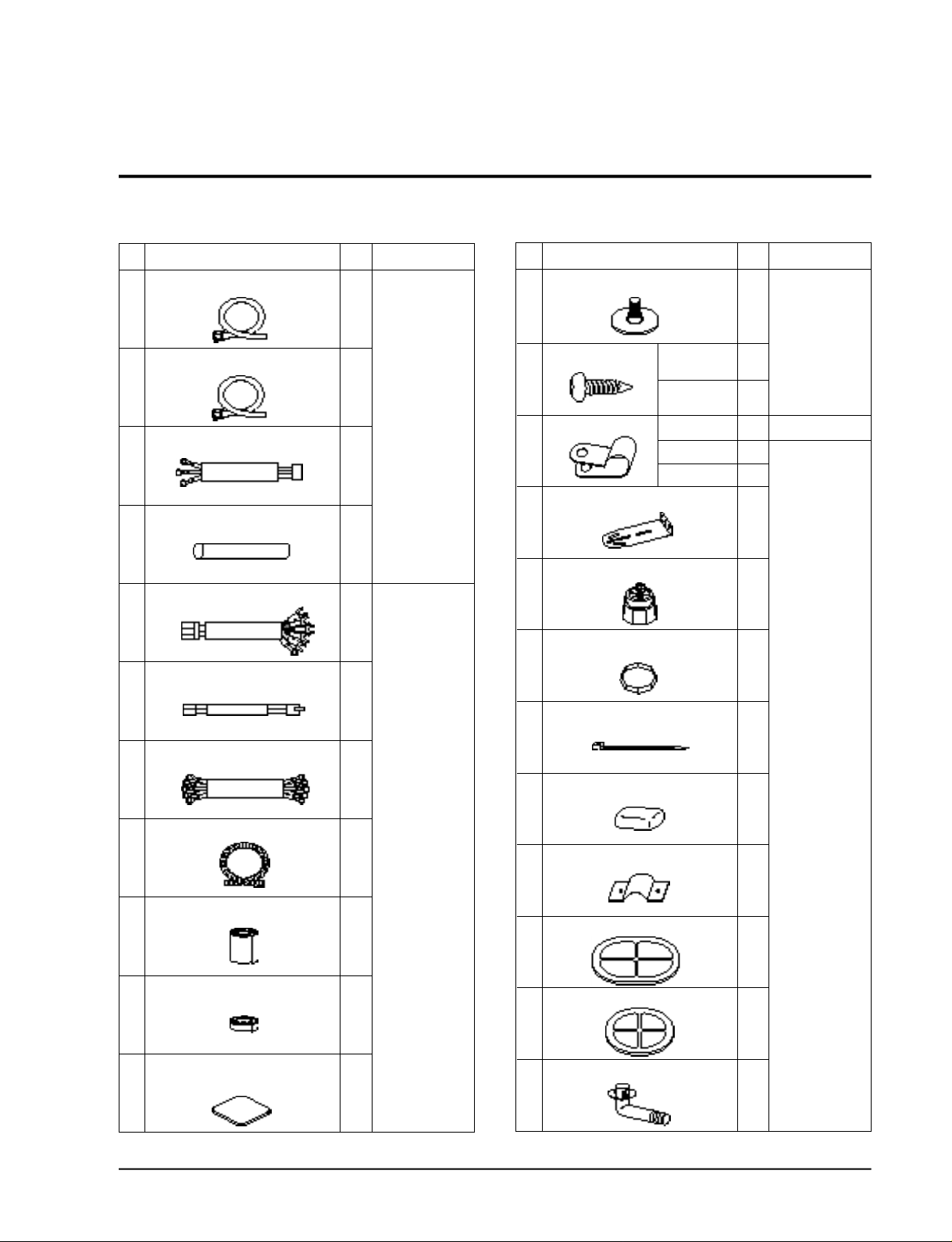
3-3 Accessory Parts List
3-3-1 Connection Parts 3-3-2 Others
No.
Connecting pipe
1
Connecting pipe
2
Heater cable (3 strand)
3
Protection tube
4
Connecting wire (7 strand)
5
Wire of sensor (2 strand)
6
Power cable
7
Drain hose
8
Finishing tape
9
Part Name Q’ty Remarks
3/8”
(ø9.52mm)
3/4”
(ø19.05mm)
1
1
1
1
1
1
1
1
2
Option
(Piping box)
Piping box
No.
Leg holder for indoor unit
1
Screw
2
Cable clamp
3
Indoor unit fixing holder
4 1
Leg holder for outdoor unit
5
Insulation rubber bottom
6
Cable tie
7
Putty
8
Pipe band
9
Rubber cabi slot
10
Part Name Q’ty Remarks
TH M4 X 12
TH M4 X 25
12N
8N
6N
4
Piping box
4
4
2
Option(Piping box)
3
1
4
4
5
Piping box
3
3
1
Insulation tape
10
Insulation tube for indoor
unit piping connection
11
Samsung Electronics
1
1
Rubber cabi hole
11
Drain plug out
12 1
1
3-3
3-4 Installation
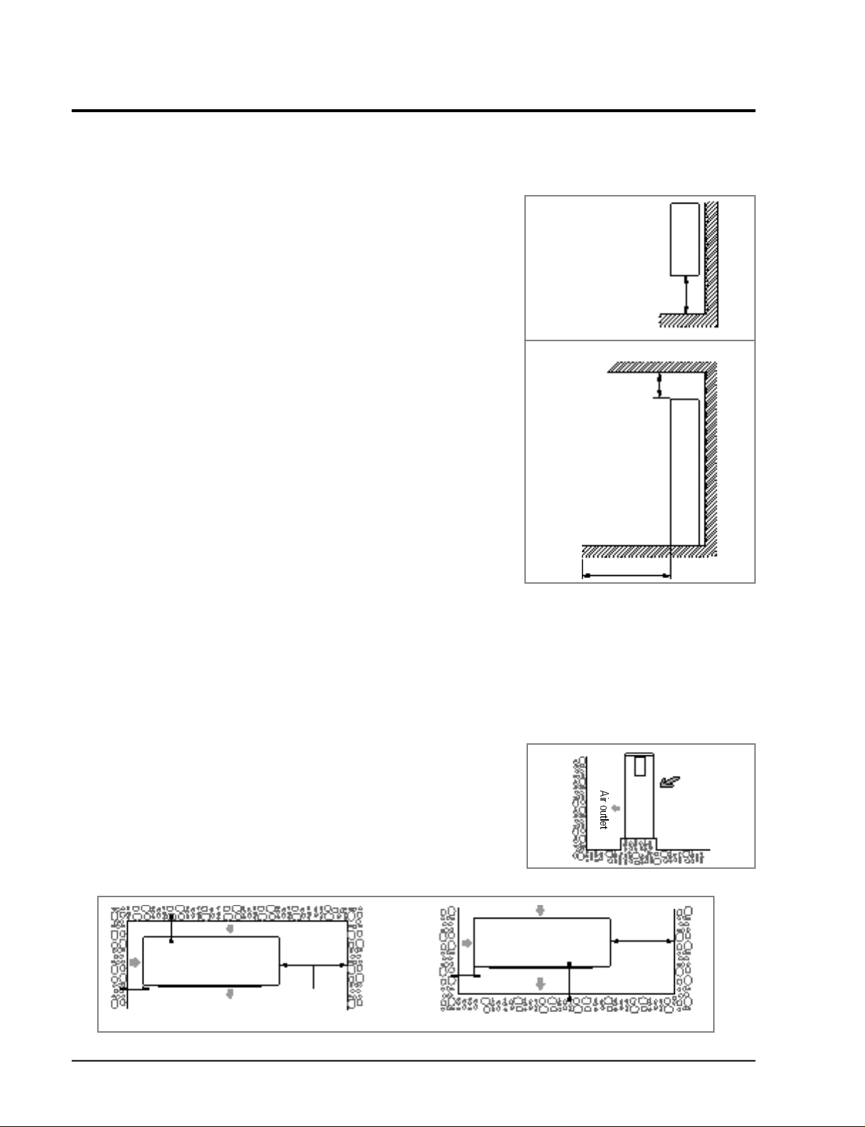
3-4-1 Selection of Installation Place
3-4-1(a) Indoor Unit
• Install the unit at a place close to the wall facing the outside
as it is necessary to perform piping connection with the out-
Top view
door unit.
- It is effective to install the unit at a window side to ensure
uniform distribution of indoor temperature .
• Install the unit at a place where there is no obstacle against
the wind around the air inlet and air outlet.
Above 50cm
• Install the unit horizontally at a stable, rigid place.
(When installing the unit at a place subjected to vibration,
noise may occur. )
• Avoid a place near the door which is frequented by people.
• Avoid a place subject to direct sunlight.
Side view
Above 20cm
3-4-1(b) Outdoor Unit
• Place free from the risk of combustible gas leakage.
• Place which can bear the weight of the unit.
• Place which can bear the fixing strength of the outdoor unit.
• Avoid a place subject to oil (including machine oil).
• Avoid a saline place.
• Avoid a place subject to sulfide gas (hot spring zone).
(When installing the unit at such special environmental
conditions, it may cause machine trouble. When it is
unavoidable to use such places. It re q u i res special
m a i n t e n a n c e . )
• A place where the discharge air and noise of the outdoor unit do not disturb the neighborh o o d .
(Take special care not to cause any inconvenience to your neighbors when installing the unit on
the borderline with your neighborh o o d . )
• A place where strong wind does not head against the air outlet of the outdoor unit.
(If a strong wind heads directly against the air outlet at the time of cool operation, a safety device
can be operated.)
• Do not install the outdoor unit at an unstable place such as outer wall of an apartment or building.
The outdoor unit may fall down, causing severe personal or property damage or loss.
Above 100cm
* If there is any unavoidable reason to install the unit at such
a place, take the following measures against the wind;
1. When installing the unit at a roadside concentrated with
buildings, install it parallel with the ro a d .
Wall
2. Install the unit so that the air outlet faces toward the wall
at a place such as rooftop, which may be subjected to
s t rong wind.
* The outdoor unit should be installed in accordance with the service space.
Above 15cm
Above 50cm
Above 15cm
Space for piping
and wiring
The air inlet faces toward the wall.
Above 15cm
The air outlet faces toward the wall.
3-4
Strong wind
Roof top
Above 50cm
Space for piping
and wiring
Above 30cm
Samsung Electronics
Operating instructions and Installation
3-4-2 Electrical Work
The electrical work should be performed by a specialist qualified for the work.
• Use the three phase power supply, and be sure to install the sub power distributing board for
exclusive use with the unit(separately purchased by the user).
* Avoid octopus-type wiring as it can cause a drop in voltage, thus resulting in poor performance
of the automatic control circ u i t .
• Be sure to install circuit breaker (separately purchased by the user).
• Be sure to connect the grounding wire .
Electric power spec
Power
Ampere of breaker
Knife switch
Switch
Fuse
Size of grounding wire
Min. size of electric wires from/to
the indoor/outdoor unit
3phase 4wires 380V
50 A
25A
25 A
2
2.5 mm
0.75 mm
2
CAUTION
• Be sure to use the wires, and switches or fuses of power distribution board are qualified and fulfill the specification.
• Be sure to install knife switch or circuit breaker on the power distribution board.
• The electrical and grounding work should be performed as per “ technical specification of electrical facilities ” and “
specification of internal wiring ”.
• Be sure to connect main electrical input wires with
bolted connectors using compressed terminal.
Applicable voltage 380V
342V ~ 418V
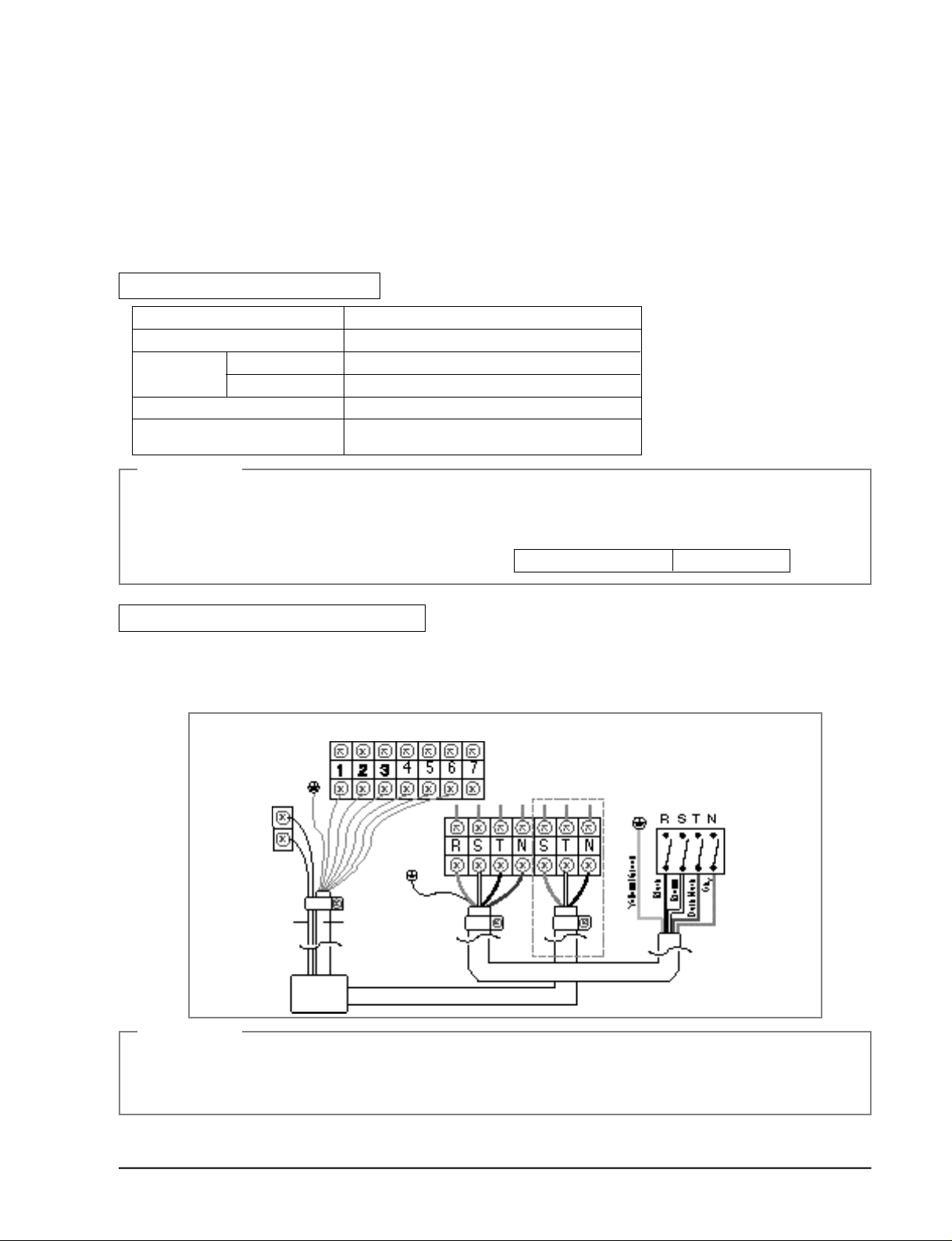
When connecting 3Phase 4wires 380V AC
1. Remove cover of electric box on side panel of outdoor unit.
2. Connect electric input wires (R,S,T,N) to each terminal (R,S,T,N) of the electric box on outdoor
unit re s p e c t i v e l y.
3 . Connect electric wires to each terminal on indoor and outdoor unit re s p e c t i v e l y.
OUTDOOR SIDE
1:Thin Brown
2:Sky
3:Brown
4:Black
5:Thin sky
6:Dark Black
Wire of sensor
Indoor/outdoor unit
connecting wire
Inoor
unit
Heater cable
Power cable
CAUTION
• Be sure to connect electrical wires correctly, if not it can cause a trouble.
* Be sure to fix wires from/to the indoor and outdoor unit on the piping insulated.
Avoid wires contact to bare pipe or valve directly without any insulated spacer.
* Must be use the approval wire according to IEC or EN requirement.
Samsung Electronics
Knife switch or
automatic circuit
breaker
3-5
 Loading...