

Samsung APH450, APH450PG0K-AFR Block Diagram
7. Block Diagrams
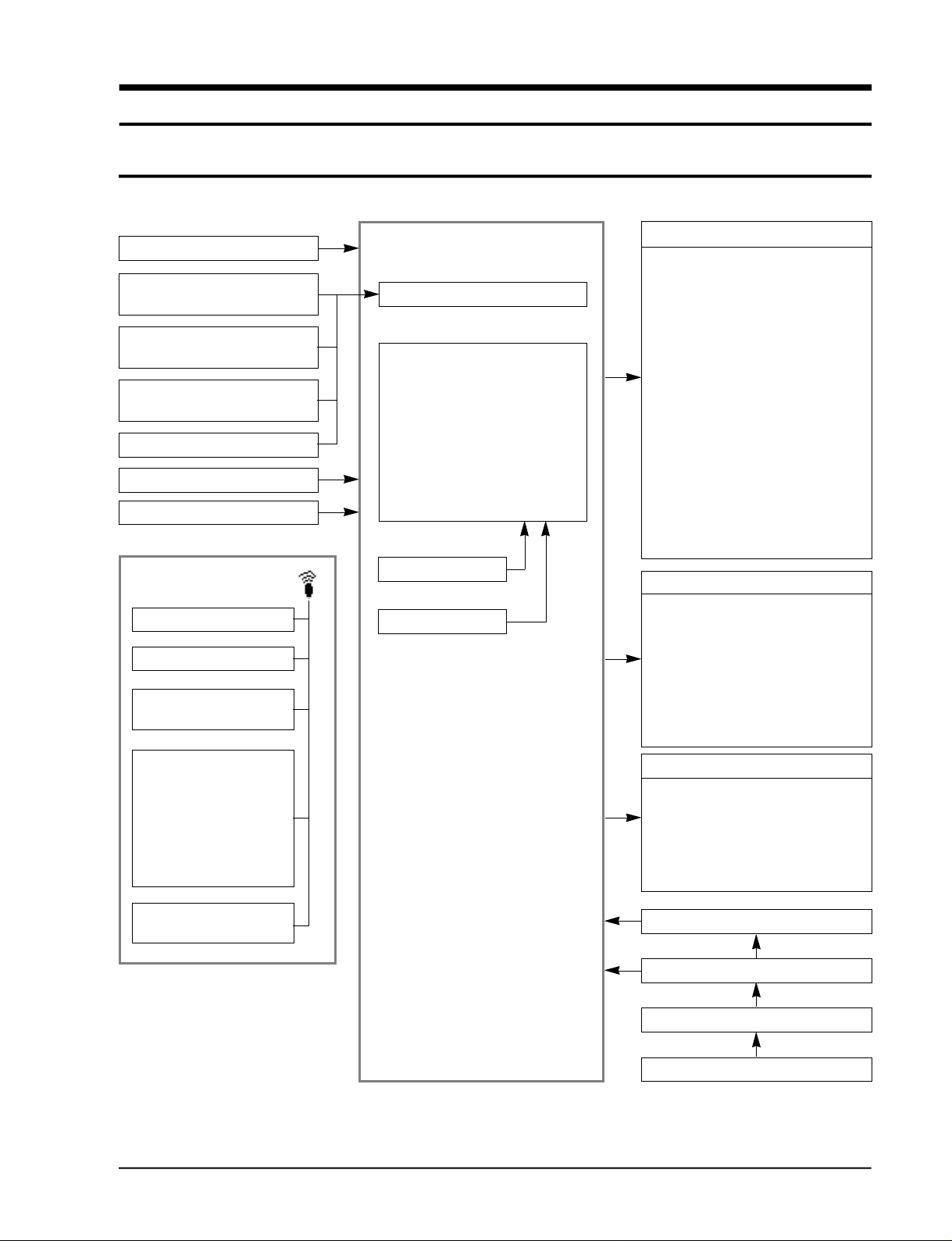
7-1 Micro Computer Block Diagram
Time condensor
Real temperature
perception sensor(R-TH)
Evaporating temperature
perception sensor
Condensing temperature
perception sensor
Over heat perception sensor
Remote control receiver
Lamp examiner
REMOTE CONTROLLER
On/Off
Left-right turn
Fan Speed selector-
high, medium, low
INDOOR CONTROL PANEL
A/D transformer
Temperature controller
Compressor controller
Heater controller
Indoor fan controller
Outdoor fan controller
Left-right motor controller
4-way valve controller
Buzzer controller
Reset circuit
Oscillator circuit
Indoor indicators
•Temperature lamp
•Cooling lamp
•Heating lamp
•Low-medium-high turbo lamp
•Timer lamp
•Power lamp
•Mode selector lamp: Auto, Heat,
cool, fan
•Outdoor unit motion lamp
•Defrosting lamp
•Lamp to indicate desired temperature
•Lamp to indicate present temperature
•Timer lamp to indicate reservation
•Lamp to indicate present time
•Turbo lamp
Operation of room switches
•On/Off
•Temperature(time) - high,
temperature(time) - low
•Function selector
•Convenience reservation
•Fan selector selector
•Change indicator
•Selector of Heater On/Off
Function selector
Heat
Cool
Fan
Turbo
Temperature control:
low, high
Samsung Electronics
Workload operation
•Indoor fan motor - low, medium, high,
turbo
•Left-right motor
•Compressor
•Outdoor fan motor
•4-way valve
Electric circuit(DC+5V)
Electric circuit(DC+12V)
Electric transformer
Electric power input
7-1
High
Pressure
switch
Capillary tube
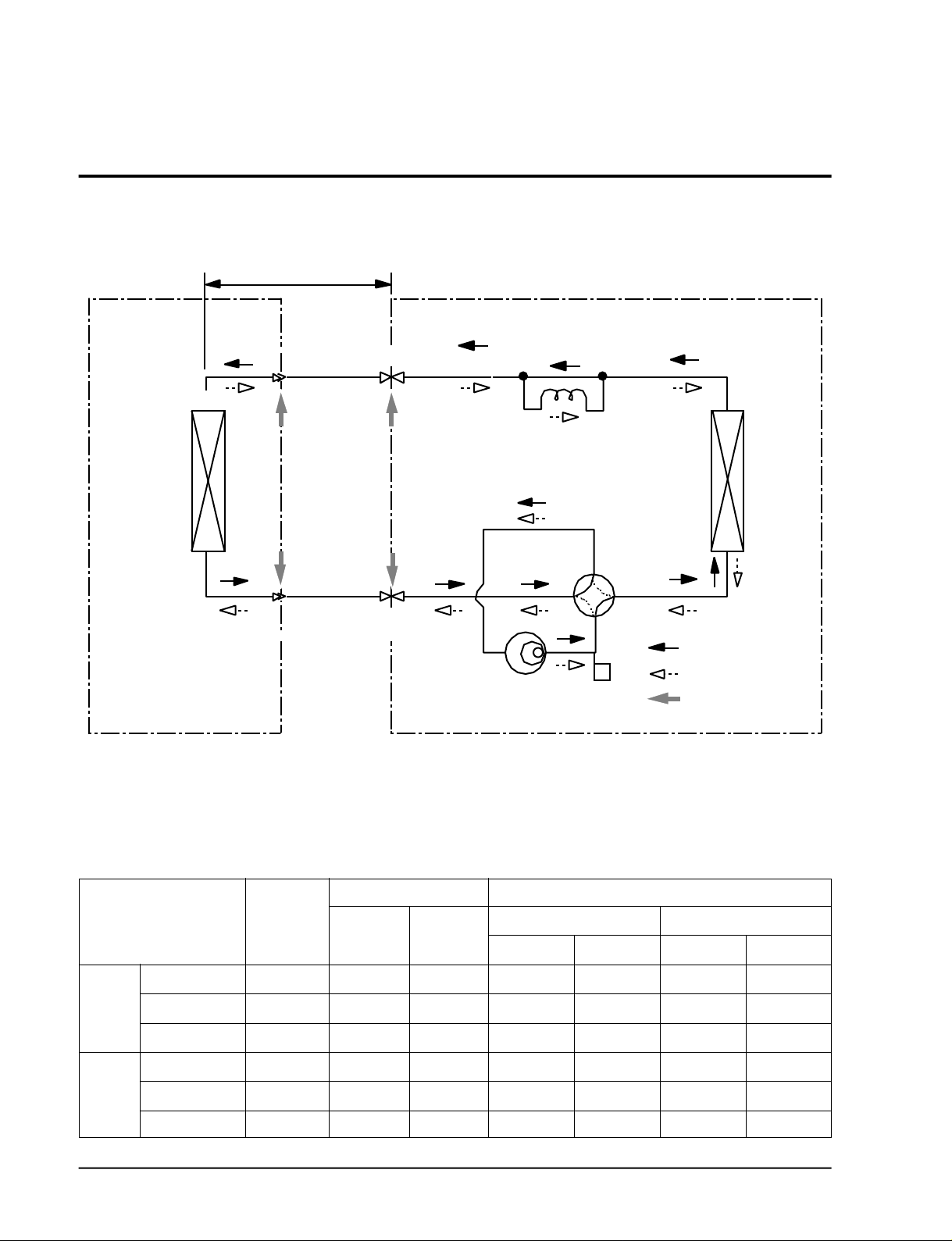
7-2 Refrigerating Cycle Block Diagram
INDOOR UNIT
Allowable pipe drop distance:Maximum 15m
Heat
exchanger
(Evaporator)
Allowavle pipe length:Maximum 25m
3-way valve
Liquid side
Gas side
3-way valve
OUTDOOR UNIT
Check valve
Capillary tube
Heat
exchanger
(Condenser)
4-way valve
Cooling
Compressor
Heating
Gas leak check point
* Amount of refilling per extension length of 1m;
When extending the pipe length by more than 5m, 50g of R-22 refrigerant should be re f i l l e d
per extension length of 1m.
Refrigerating cycle temperature and pressure
Piping Temp.(˚C) UseTemp. Condition (°C)
Indoor Outdoor
T1 T2
40~45
50~55
30~35
32~36
36~40
28~32
9~12
14~18
1~4
65~75
70~80
40~45
DB
27
32
21
20
27
20
WB
19
23
16
-
-
-
Operating Condition
Standard
Cooling
Max over load
Low temp
Standard
Heating
Max over load
Deice
STD Pressure
(kg/cm2G)
(GAS SIDE)
4.5~5.5
6.5~7.5
3~4
18.5~20.5
-
-
DB
35
43
21
21
WB
24
26
16
7
6
16
2
1
7-2
Samsung Electronics
 Loading...