

Samsung AN15V Alignment and Adjustments

4-1-1 Before Making Adjustments
4-1-1 (a) ORIENTATION
When servicing, always face the monitor to the
east.
4-1-1 (b) WARM-UP TIME
The monitor must be on for 30 minutes before
starting alignment. Warm-up time is especially
critical in color temperature and white balance
adjustments.
4-1-1 (c) SIGNAL
Analog, 0.7 Vp-p positive at 75 ohm, internal
termination
Sync: TTL level, negative/positive
4-1-1 (d) SCANNING FREQUENCY
Horizontal: 30 KHz ~ 55 KHz (Automatic)
Vertical: 50 Hz ~ 120 Hz (Automatic)
Unless otherwise specified, adjust at the
800 x 600 mode (54 KHz/85 Hz).
4-1-2 Required Equipment
The following equipment may be necessary for
adjustment procedures:
4-1-2 (a) DISPLAY CONTROL ADJUSTMENT
1. Non-metallic (–) screwdriver:
1.5, 2.5, 3 mm
2. Non-metallic (+) screwdriver:
1.5, 2.5, 3 mm
3. Digital Multimeter (DMM), or
Digital Voltmeter
4. Signal generator, or
DM200 software
5. Personal computer
4-1-2 (b) COLOR ADJUSTMENTS
1. All equipment listed in 4-1-2 (a), above
2. Color analyzer, or any luminance
measurement equipment
AN15V* 4-1
4 Alignment and Adjustments
This section of the service manual explains how to make permanent adjustments to the monitor. Directions
are given for adjustments using the monitor Interface Board Ver. 1.1 and software (Softjig).
4-1 Adjustment Conditions
Caution: Changes made without the Softjig are saved only to the user mode settings. As such, the
settings are not permanently stored and may be inadvertently deleted by the user.
CONFIDENTIAL
4 Alignment and Adjustments
4-2 AN15V*
CONFIDENTIAL
4-2-1
HIGH VOLTAGE
Signal: 800 x 600 (54 KHz/85 Hz)
Display image: Full White Pattern
Contrast: Maximum
Brightness: Maximum
Limit: 25.0 kV ± 0.2 kV
Measure the hight voltage level at the anode cap.
High voltage should be within the limit as above.
4-2-2 CENTER RASTER
Adjust VR401 so that the back raster comes to the
center when you apply each basic mode.
SCREEN VOLTAGE ADJUSTMENT
❈ This can only SDI CRT conditions.
Signal: 800 x 600 (54 KHz/85 Hz)
Display image: Don’t care
Contrast: Minimum
Brightness: Minimum
Limit: 480 ± 10V
Adjust screen VR of T501.
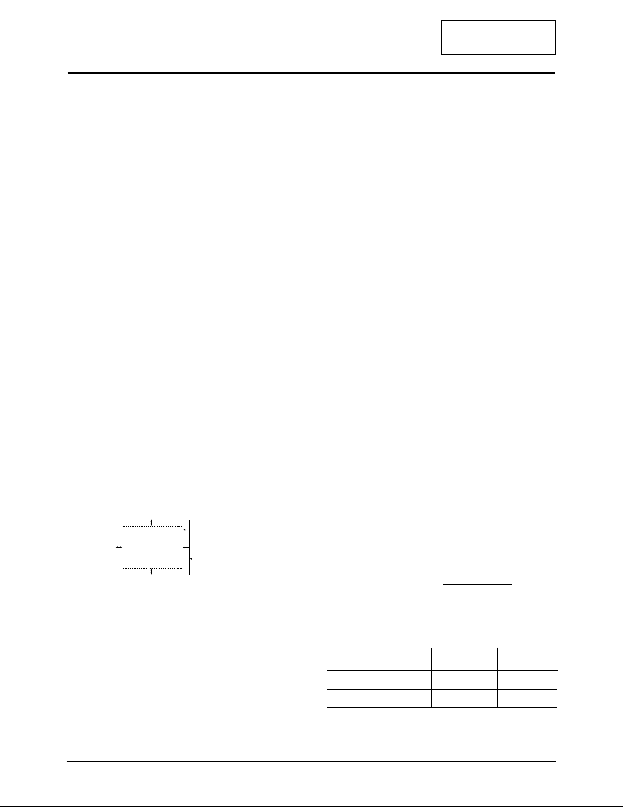
4-2-3 Centering
Centering means to position the center point of
the display in the middle of the display area.
Horizontal size and position and vertical size and
position control the centering of the display.
Adjust the horizontal size and vertical size to their
optimal settings: 267 mm (H) x 200 mm.
Adjust the horizontal position and vertical
position to ≤ 5.0 mm of the center point of the
screen.
|A – B| ≤ 5.0 mm. |C – D| ≤ 5.0 mm.
Figure 4-3. Centering
4-2-3 (a-1) HORIZONTAL SIZE ADJUSTMENT
CONDITIONS
Scanning frequency: 54 KHz/85 Hz
Display image: Crosshatch pattern
Brightness: Maximum
Contrast: Maximum
Use control bar after selecting “SIZE B+” in left
menu to adjust the horizontal size of the display
pattern to 255 mm . (Tolerance: ± 4 mm.)
4-2-3 (a-2) HORIZONTAL SIZE ADJUSTMENT
Use control bar after selecting “H-SIZE” in left
menu to adjust the horizontal size of the display
pattern to 267 mm . (Tolerance: ± 4 mm.)
4-2-3 (b) VERTICAL SIZE ADJUSTMENT
CONDITIONS
Scanning frequency: 54 KHz/85 Hz
Display image: Crosshatch pattern
Brightness: Maximum
Contrast: Maximum
Use control bar after selecting “V-SIZE” in left
menu to adjust the vertical size of the display
pattern to 200 mm. (Tolerance: ± 4 mm.)
4-2-3 (c) HORIZONTAL POSITION ADJUSTMENT
CONDITIONS
Scanning frequency: 54 KHz/85 Hz
Display image: Crosshatch pattern
Use control bar after selecting “H-POSITION” in
left menu to center the horizontal image on the
raster.
4-2-3 (d) VERTICAL POSITION ADJUSTMENT
CONDITIONS
Scanning frequency: 54 KHz/85 Hz
Display image: Crosshatch pattern
Use control bar after selecting “V-POSITION” in
left menu to center the vertical image on the
raster.
4-2-4 Linearity
Linearity affects the symmetry of images as they
appear on the screen. Unless each row or column
of blocks in a crosshatch pattern is of equal size,
or within the tolerances shown in Table 4-1 an
image appears distorted, elongated or squashed.
Horizontal Linearity = 2x x100
Vertical Linearity = 2x x100
Table 4-1
❈ Preset Mode : 54KHz / 85Hz
Pre-load Mode : Refer to Timing Chart
4-2 Display Control Adjustments
C
A
DISPLAY AREA
EDGE OF BEZEL
B
D
X max-X min
X max+X min
Y max-Y min
Y max+Y min
Preset mode ≤ 4% ≤ 8%
Adjacent Linearity
Entire Linearity
Pre-load mode (48kHz~) ≤ 5% ≤ 14%
 Loading...