

Samsung AM***FN*D series, AM***MN*D series, AM**JNM series User Manual

Air conditioner
User manual
AM
777FN7D77
/ AM
777
JNM77 / AM
777MN7D77
ŷ Thank you for purchasing this Samsung air conditioner.
ŷ Before operating this unit, please read this user manual carefully and retain it for future
reference.


2
A
Contents
Safety precautions ......................................................................................................................................................3
Accessories ....................................................................................................................................................................5
Selecting the installation location ..........................................................................................................................6
Indoor unit installation .......................................................................................................................................... 20
Purging the unit ....................................................................................................................................................... 21
Connecting the refrigerant pipe .......................................................................................................................... 21
Cutting/aring the pipes ........................................................................................................................................ 23
Performing leak test & insulation ........................................................................................................................ 24
Drain pipe and drain hose installation ............................................................................................................... 26
Wiring work ............................................................................................................................................................... 30
Setting an indoor unit address and installation option ................................................................................. 33
Setting temperature control of discharge air ................................................................................................... 44
Final check and trial operation ............................................................................................................................. 44
Providing information for user ............................................................................................................................. 45
Troubleshooting ....................................................................................................................................................... 45
Adjusting air ow ..................................................................................................................................................... 47
Extending the power cable ................................................................................................................................... 53

3
A
ENGLISH
Safety precautions
(Carefully follow the precautions listed below because they are essential to guarantee the safety of the
equipment.)
WARNING
xAlways disconnect the air conditioner from the power supply before servicing it or
accessing its internal components.
x
Verify that installation and testing operations are performed by qualified personnel.
xVerify that the air conditioner is not installed in an easily accessible area.
GENERAL INFORMATION
X Carefully read the content of this manual before installing the air conditioner and store the manual in a safe place in
order to be able to use it as reference after installation.
X For maximum safety, installers should always carefully read the following warnings.
X Store the operation and installation manual in a safe location and remember to hand it over to the new owner if the
air conditioner is sold or transferred.
X This manual explains how to install an indoor unit with a split system with two SAMSUNG units. The use of other types
of units with different control systems may damage the units and invalidate the warranty. The manufacturer shall not
be responsible for damages arising from the use of non compliant units.
X
The manufacturer shall not be responsible for damage originating from unauthorized changes or the improper connection
of electric and hydraulic lines. Failure to comply with these instructions or to comply with the requirements set forth in the
“Operating limits” table, included in the manual, shall immediately invalidate the warranty.
X The air conditioner should be used only for the applications for which it has been designed: the indoor unit is not
suitable to be installed in areas used for laundry.
X Do not use the units if damaged. If problems occur, switch the unit off and disconnect it from the power supply.
X In order to prevent electric shocks, fires or injuries, always stop the unit, disable the protection switch and contact
SAMSUNG’s technical support if the unit produces smoke, if the power cable is hot or damaged or if the unit is very
noisy.
X Always remember to inspect the unit, electric connections, refrigerant tubes and protections regularly.
These operations should be performed by qualified personnel only.
X The unit contains moving parts, which should always be kept out of the reach of children.
X Do not attempt to repair, move, alter or reinstall the unit. If performed by unauthorized personnel, these operations
may cause electric shocks or fires.
X Do not place containers with liquids or other objects on the unit.
X
All the materials used for the manufacture and packaging of the air conditioner are recyclable.
X The packing material and exhaust batteries of the remote control(optional) must be disposed of in accordance with
current laws.
X The air conditioner contains a refrigerant that has to be disposed of as special waste. At the end of its life cycle, the air
conditioner must be disposed of in authorized centers or returned to the retailer so that it can be disposed of correctly
and safely.
INSTALLING THE UNIT
IMPORTANT: When installing the unit, always remember to connect first the refrigerant tubes, then the electrical lines.
Always disassemble the electric lines before the refrigerant tubes.
X Upon receipt, inspect the product to verify that it has not been damaged during transport. If the product appears
damaged, DO NOT INSTALL it and immediately report the damage to the carrier or retailer (if the installer or the
authorized technician has collected the material from the retailer.)
X After completing the installation, always carry out a functional test and provide the instructions on how to operate
the air conditioner to the user.
X Do not use the air conditioner in environments with hazardous substances or close to equipment that release free
flames to avoid the occurrence of fires, explosions or injuries.
X The air conditioner should be used only for the applications for which it has been designed: the indoor unit is not
suitable to be installed in areas used for laundry.
4
A
X Our units must be installed in compliance with the spaces indicated in the installation manual to ensure either
accessibility from both sides or ability to perform routine maintenance and repairs. The units’ components must be
accessible and that can be disassembled in conditions of complete safety either for people or things.
For this reason, where it is not observed as indicated into the Installation Manual, the cost necessary to reach and repair
the unit (in safety, as required by current regulations in force) with slings, trucks, scaffolding or any other means of
elevation won’t be considered in-warranty and charged to end user.
POWER SUPPLY LINE, FUSE OR CIRCUIT BREAKER
X Always make sure that the power supply is compliant with current safety standards. Always install the air conditioner in
compliance with current local safety standards.
X Always verify that a suitable grounding connection is available.
X Verify that the voltage and frequency of the power supply comply with the specifications and that the installed power is
sufficient to ensure the operation of any other domestic appliance connected to the same electric lines.
X Always verify that the cut-off and protection switches are suitably dimensioned.
X Verify that the air conditioner is connected to the power supply in accordance with the instructions provided in the
wiring diagram included in the manual.
X Always verify that electric connections (cable entry, section of leads, protections…) are compliant with the electric
specifications and with the instructions provided in the wiring scheme. Always verify that all connections comply with
the standards applicable to the installation of air conditioners.
X Make sure that you earth the cables.
- Do not connect the earth wire to the gas pipe, water pipe, lighting rod or telephone wire.
If earthing is not complete, electric shock or fire may occur.
X
Install the circuit breaker.
- If the circuit breaker is not installed, electric shock or fire may occur.
X
Make sure that the condensed water dripping from the drain hose runs out properly and safely.
X Install the power cable and communication cable of the indoor and outdoor unit at least 1m
away from the electric appliance.
X
Install the indoor unit away from lighting apparatus using the ballast.
- If you use the wireless remote control, reception error may occur due to the ballast of the
lighting apparatus.
X
Do not install the air conditioner in following places.
- Place where there is mineral oil or arsenic acid.
Resin parts flame and the accessories may drop or water may leak.
The capacity of the heat exchanger may reduce or the air conditioner may be out of order.
- The place where corrosive gas such as sulfurous acid gas generates from the vent pipe or air
outlet.
The copper pipe or connection pipe may corrode and refrigerant may leak.
- The place where there is a machine that generates electromagnetic waves.
The air conditioner may not operate normally due to control system.
- The place where there is a danger of existing combustible gas, carbon fiber or flammable
dust.
The place where thinner or gasoline is handled.
Gas may leak and it may cause fire.
Safety precautions
Caution
5
A
ENGLISH
Accessories
The following accessories are supplied with the indoor unit.
The type and quantity may differ depending on the specifications.
❈ Only AM018JNMPCH/AA include the last four accessories.
Insulation cover Thermal insulation A
(use for refrigerant pipe)
Thermal insulation B
(use for refrigerant pipe)
Thermal insulation
(use for drain hose)
User's manual Installation manual Flexible hose clamp Grommet
Cable tie Flexible hose Reducer
NIPPLE-CONNECTOR
(3/8"ĺ1/4")
NIPPLE-CONNECTOR
(5/8"ĺ1/2")
FASTENER-NUT FLARE
(1/4")
FASTENER-NUT FLARE
(1/2")
6
A
Selecting the installation location
X There must be no obstacles near the air inlet and outlet.
X Install the indoor unit on a ceiling that can support its weight.
X Maintain sufficient clearance around the indoor unit.
X Make sure that the water dripping from the drain hose runs away correctly and safely.
X The indoor unit must be installed in this way, that they are out of public access. (Not touchable by the
users)
X
After connecting a chamber, insulate the connection part between the indoor unit and the chamber
with T0.39"(10) or thicker insulation. Otherwise, there can be air leak or dew from the connection part.
X Rigid wall without vibration.
X Where it is not exposed to direct sunshine.
X Where the air filter can be removed and cleaned easily.
z You must have 0.79inch (20mm) or more space between the ceiling and the bottom of indoor unit. Otherwise, the
noise from the vibration of indoor unit may bother the user.When the ceiling is under construction, the hole for
check-up must be made to take service, clean and repair the unit.
z It is possible to install the unit at an height of between 7.3~8.3ft(2.2~2.5m) from the ground, if the unit has a duct
with a well defined lenght (11.81inch(300mm) or more), to avoid fan motor blower contact.
X
Construction Standard for Inspection Hole.
1) In case, the ceiling is textile, Inspection hole dose not need.
2) In case, the ceiling is plaster board, Inspection hole depends on Inside height of the ceiling.
a. Height is more than 1.64ft(0.5m) : Only “B” [Inspection for PBA] is applied.
b. Height is less than 1.64ft(0.5m) : Both “A” & ”B” are applied.
c. “A” & ”B” are inspection holes.
Unit Width(W)
“A”=W+
3.94inch(100mm)
“B”=19.7inch(500mm)
Unit Depth(D)
0.79inch(20mm)
or more
0.79inch(20mm)
or more
"
'SPOU
$
#
#BDL
%
X I nsulate the end of the pipe and some curved area by using separate insulator.
X I nsulate the discharge and suction part at the same time when you insulate connection duct.
X
If the humidity is over 80%, it is required to add 0.39inch(10mm) polyethylene foam or other
similar insulation to the indoor unit when installing belt or pipe type indoor unit on the ceiling.
Indoor Unit
Space requirements for installation & service
Insulation Guide
7
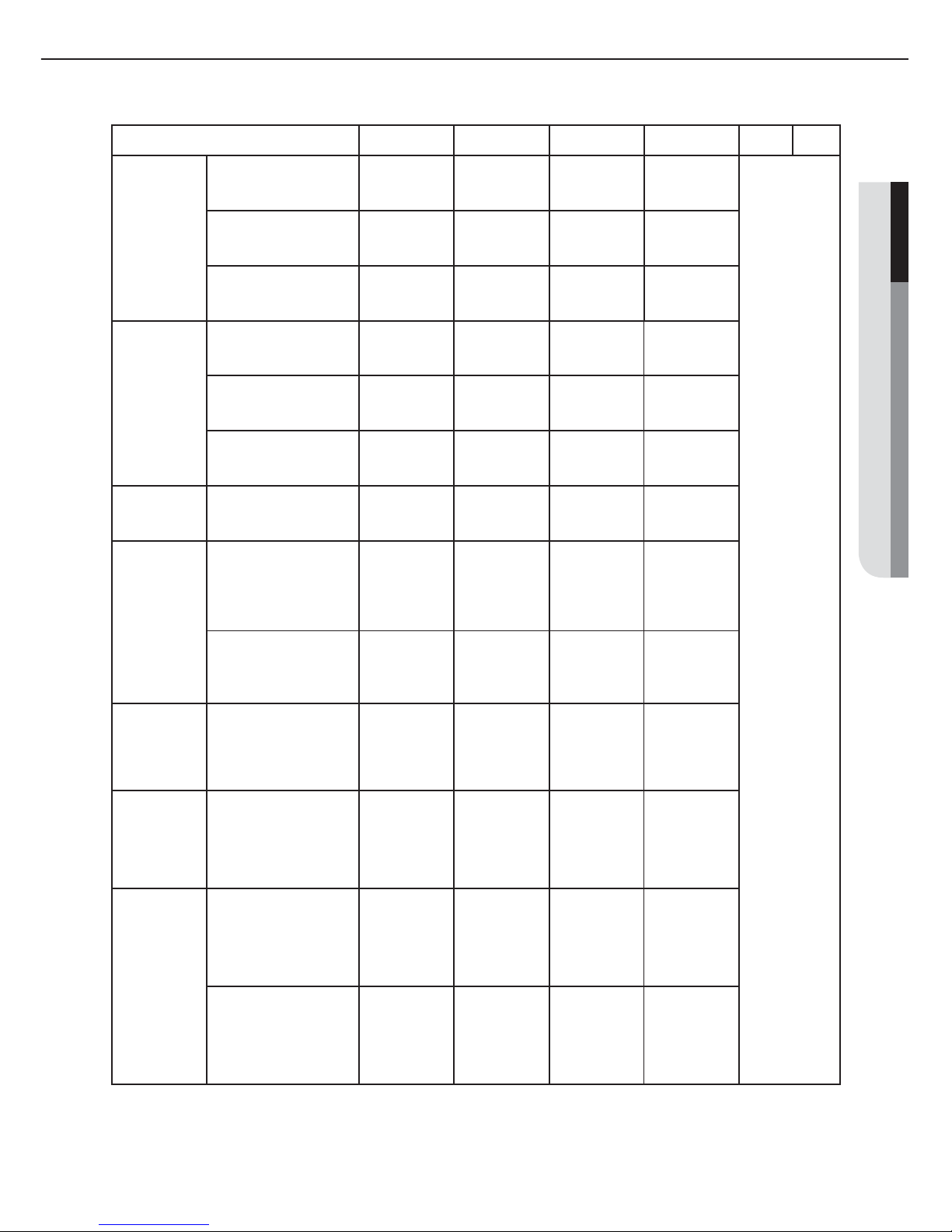
ENGLISH
Thickness:more than 0.39inch (10mm)
Indoor unit A B C D Front Back
Slim Duct
AM7FNLD7
7
0077/70097/7012
7
35.43"x7.83"23.62"
(900x199x600)
35.43"×23.62"
(900x600)
35.43"×23.62"
(900x600)
23.62"×7.87"
(600x200)
23.62"×7.87"
(600x200)
Insulate the front
and back side
in proper size at
the same time
when insulating
the suction duct
and discharge
duct.
7
0187/7024
7
43.31"x7.83"x23.62"
(1100x199x600)
43.31"×23.62"
(1100x600)
43.31"×23.62"
(1100x600)
23.62"×7.87"
(600x200)
23.62"×7.87"
(600x200)
7
0307/70367/7048
7
51.18"x11.61"27.17"
(1300x295x690)
51.18"×27.17"
(1300x690)
51.18"×27.17"
(1300x690)
27.17"×11.81"
(690x300)
27.17"×11.81"
(690x300)
MSP Duct
AM7FNMD7
7
0187/7024
7
35.43"×18.90"x10.24"
(900x480x260)
35.43"×18.90"
(900x480)
35.43"×18.90"
(900x480)
18.90"×10.24"
(480x260)
18.90"×10.24"
(480x260)
7
0307/70367
45.28"×18.90"x12.60"
(1150x480x320)
45.28"×18.90"
(1150x480)
45.28"×18.90"
(1150x480)
18.90"×12.60"
(480x320)
18.90"×12.60"
(480x320)
7
048
7
47.24"x25.59"×14.17"
(1200x650x360)
47.24"×25.59"
(1200x650)
47.24"×25.59"
(1200x650)
25.59"×14.17"
(650x360)
25.59"×14.17"
(650x360)
HSP Duct
AM7FNHD7
7
0367/
7
048
7
47.24"x25.59"×14.17"
(1200x650x360)
47.24"×25.59"
(1200x650)
47.24"×25.59"
(1200x650)
25.59"×14.17"
(650x360)
25.59"×14.17"
(650x360)
MSP Duct
AM7JNMD7
AM7JNMP7
(Drain pump
built-in)
7D7:7
0077/70097/
7
0127/70157/70187
7P7:7
006
7
45.28"×18.90"x12.60"
(1150x480x320)
45.28"×18.90"
(1150x480)
45.28"×18.90"
(1150x480)
18.90"×12.60"
(480x320)
18.90"×12.60"
(480x320)
7P7:7
0187/70287/
7
042
7
47.24"x25.59"×14.17"
(1200x650x360)
47.24"×25.59"
(1200x650)
47.24"×25.59"
(1200x650)
25.59"×14.17"
(650x360)
25.59"×14.17"
(650x360)
HSP Duct
AM7JNHD7
(Drain pump
built-in)
7
0247/70277/70307/
7
0367/70487/7054
7
47.24"x25.59"×14.17"
(1200x650x360)
47.24"×25.59"
(1200x650)
47.24"×25.59"
(1200x650)
25.59"×14.17"
(650x360)
25.59"×14.17"
(650x360)
Duct S
AM7MNMD
7
(Drain pump
built-in)
7
0077/7009/70127/
0157/70187*
33.46x27.56x9.84
(850x700x250)
33.46"x27.56
"
(850x700)
33.46"x27.56
"
(850x700)
27.56"x9.84
"
(700x250)
27.56"x9.84
"
(700x250)
Duct S
AM7MNHD
7
(Drain pump
built-in)
7
0247/70277/7030
7
47.24x27.56x9.84
(1200x700x250)
47.24"x27.5
"
(1200x700)
47.24"x27.5
"
(1200x700)
27.56"x9.84
"
(700x250)
27.56"x9.84
"
(700x250)
7
0367/7048
7
51.18*27.56*11.81
(1300x700x300)
51.18"x27.56
"
(1300x700)
51.18"x27.56
"
(1300x700)
27.56"x11.81
"
(700x300)
27.56"x11.81
"
(700x300)
8
Selecting the installation location
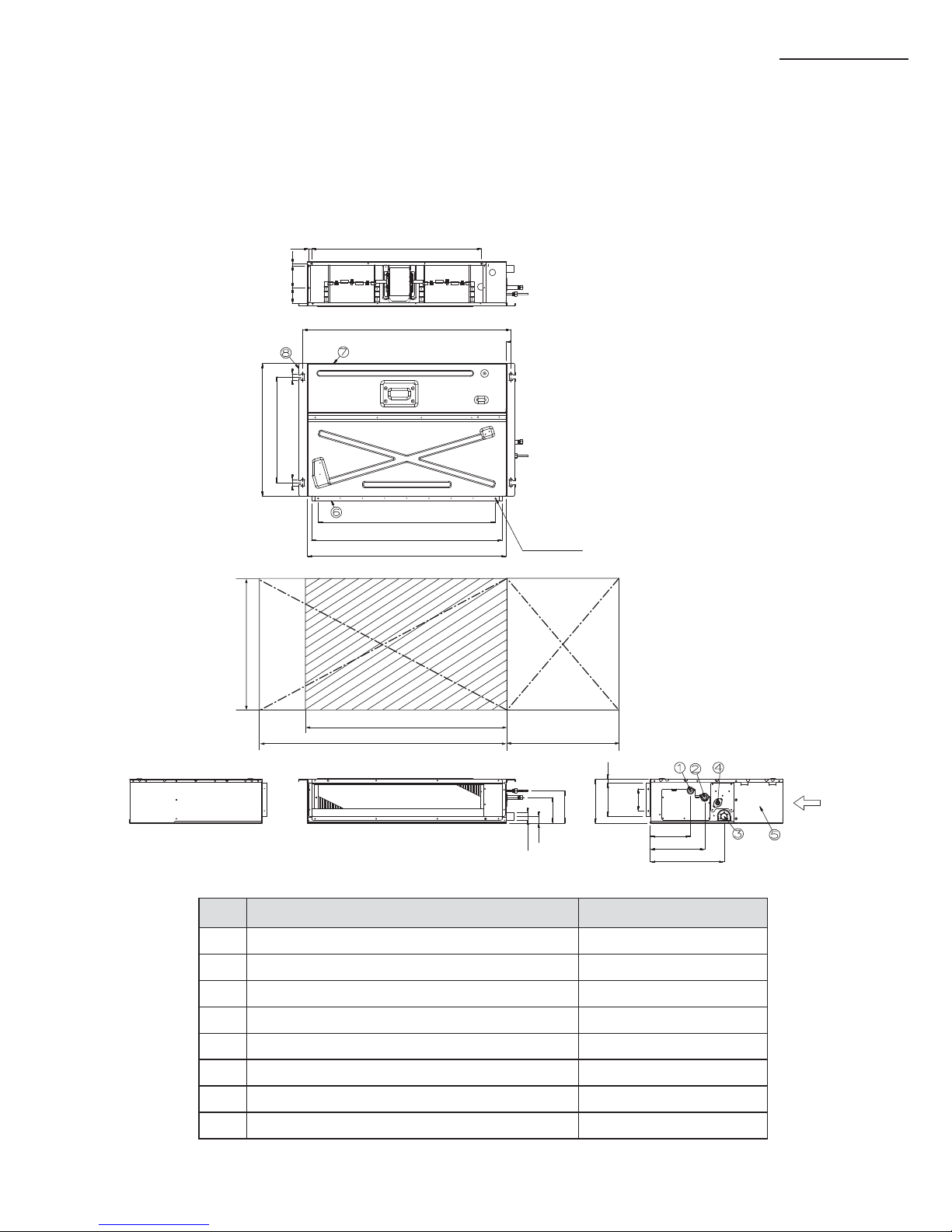
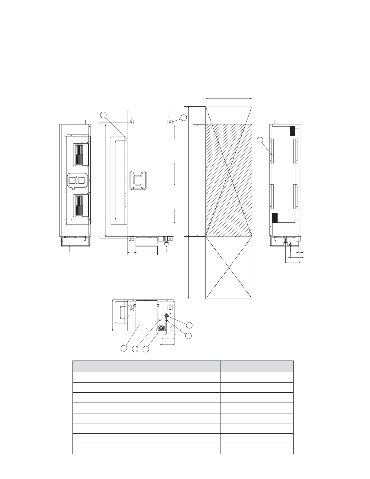
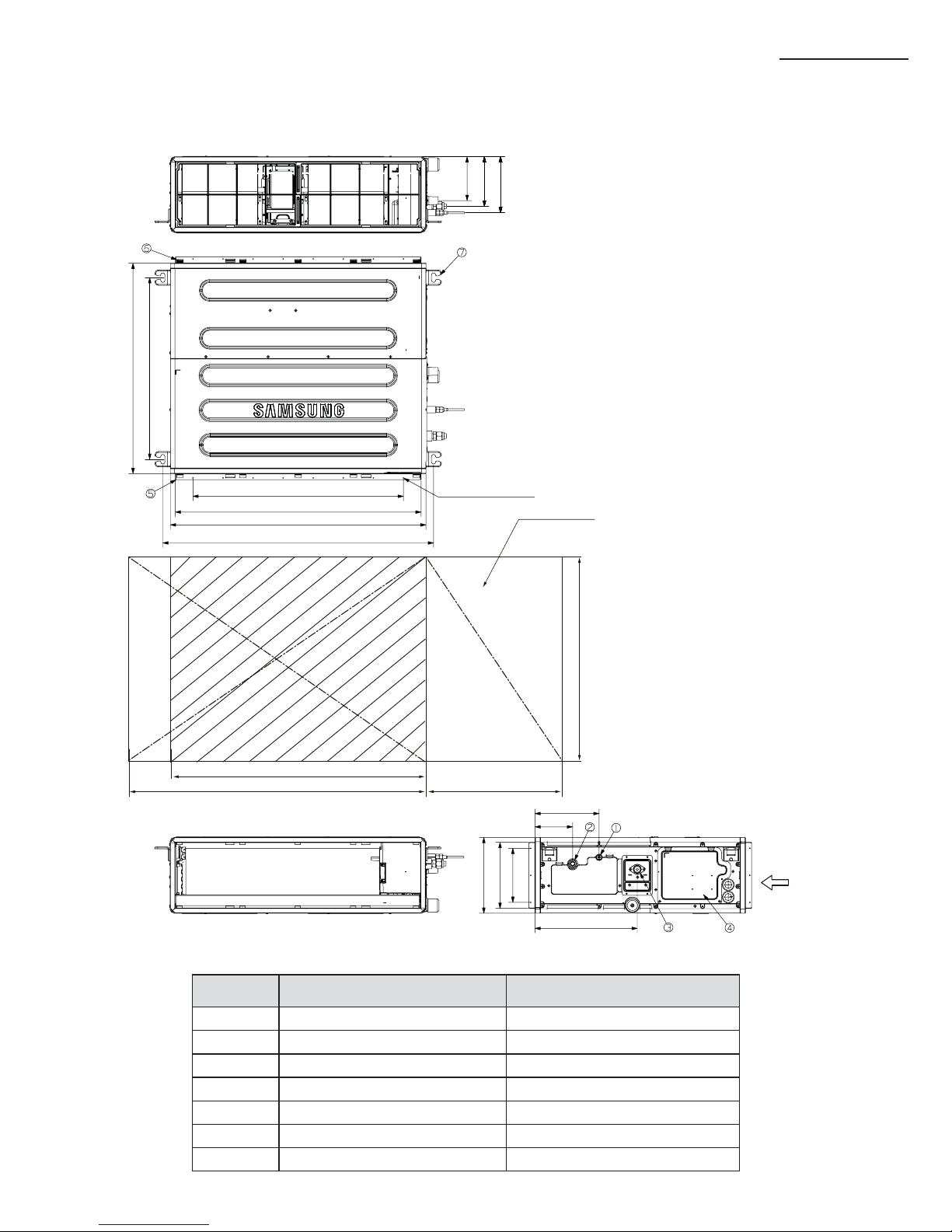
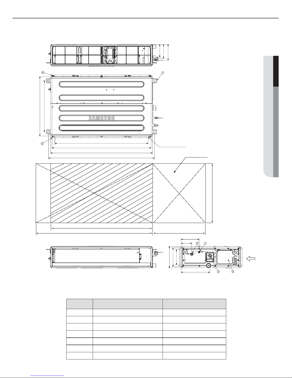
AM007/009/012FNLD777
No. Name Description
1 Liquid pipe connection ø6.35
(1/4”)
2 Gas pipe connection ø12.70
(1/2”)
3 Drain pipe connection
3/4"(ODØ1.05"(26.67))
4 Drain pipe connection (Option drain pump)
3/4"(ODØ1.05"(26.67))
5 Power supply/Communication connection --
6 Power supply connection --
7 Air discharge grille flange --
8 Hook ø9.52(
3/8” )
or M10
11.9(0.47'')
3256=768(30.14'')
(2.80'')
71
(3.94'')
100
(0.39'')
10
938.4(36.94'') Suspension position
600(23.62'')
477(18.78'') Suspension position
8100=800(31.50'')
860(33.86'') Air outlet duct flange
900(35.43'')
22(0.87'')-ø3.2(0.13'') Hole
28(1.1'')
All around
Discharge side Suction side
199(7.83'')
151.6(5.97'')
100(3.94'')
182(7.17'')
246(9.69'')
18(0.71'')
OD32(1.26'')
30.5(1.20'')
115.5(4.55'')
145.5(5.73'')
333(13.11'')
28(1.1'')
650(25.59'')
900(35.43'')
1000(39.37'')
500(19.69'')
Unit : mm(inch)
9
ENGLISH
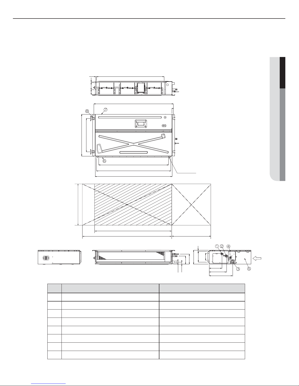
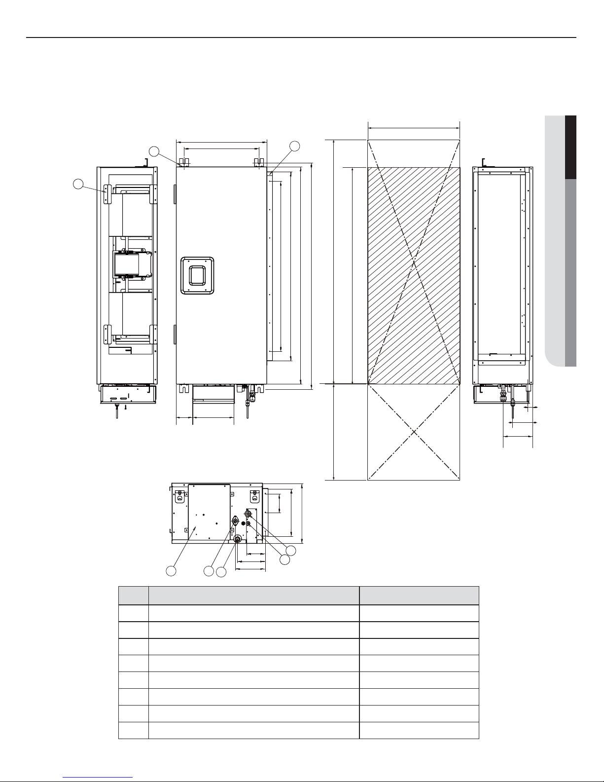
No. Name Description
1 Liquid pipe connection
601866:ø6.35(1/4") ,602466:ø9.52(3/8")
2 Gas pipe connection
601866:ø12.7(1/2") ,602466:ø15.88(5/8")
3 Drain pipe connection
3/4"(ODØ1.05"(26.67))
4 Drain pipe connection (Option drain pump)
3/4"(ODØ1.05"(26.67))
5 Power supply/Communication connection --
6 Power supply connection --
7 Air discharge grille flange --
8 Hook ø9.52(
3/8” )
or M10
AM018/024FNLD777
12.9(0.51'')
3322=966(38.03'')
1138(44.80'') Suspension position
477(18.78'') Suspension position
10100=1000(39.37'')
1060(41.73'') Air outlet duct flange
1100(43.31'')
26(1.02'')-ø3.2(0.13'') Hole
All around
Discharge side Suction side
(2.80'')
71
(3.94'')
100
(0.39'')
10
600(23.62'')
28(1.1'') 28(1.1'')
199(7.83'')
151.6(5.97'')
100(3.94'')
182(7.17'')
246(9.69'')
18(0.71'')
OD32(1.26'')
30.5(1.20'')
115.5(4.55'')
144.5(5.69'')
333(13.11'')
650(25.59'')
1100(43.31'')
1200(47.24'')
500(19.69'')
Unit : mm(inch)
10
A
Selecting the installation location
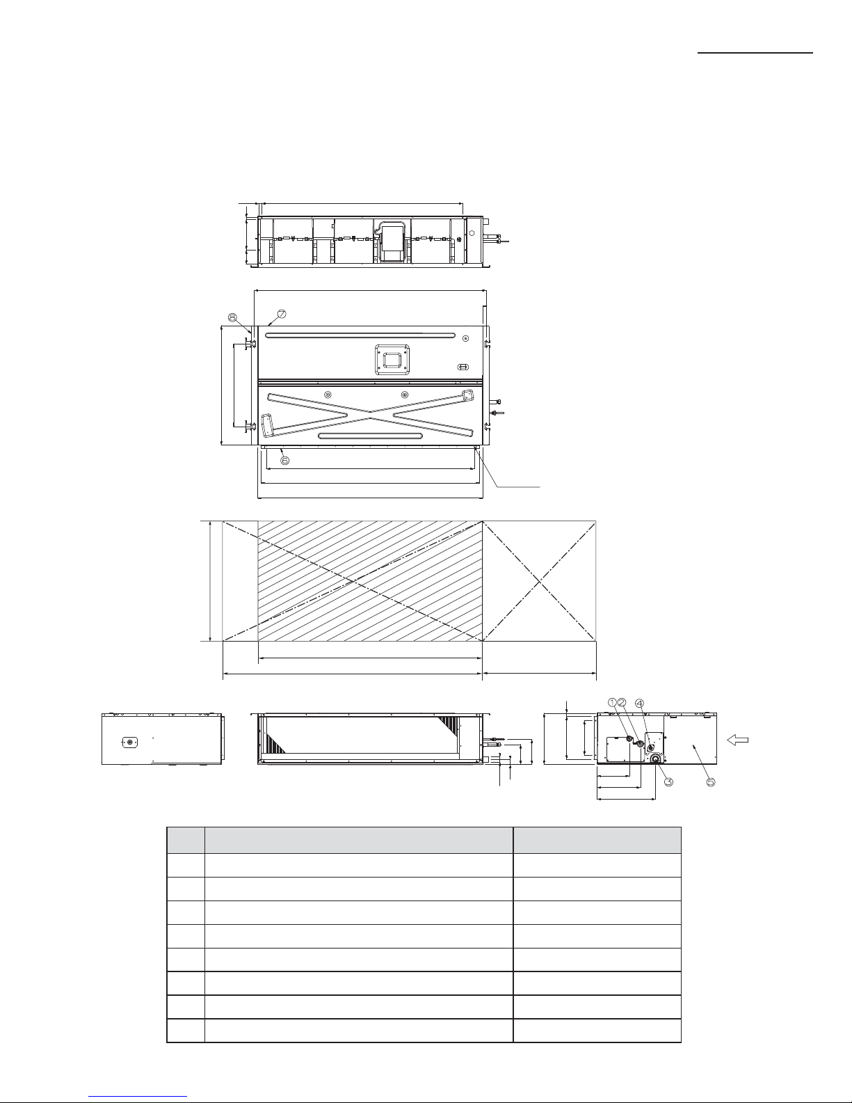
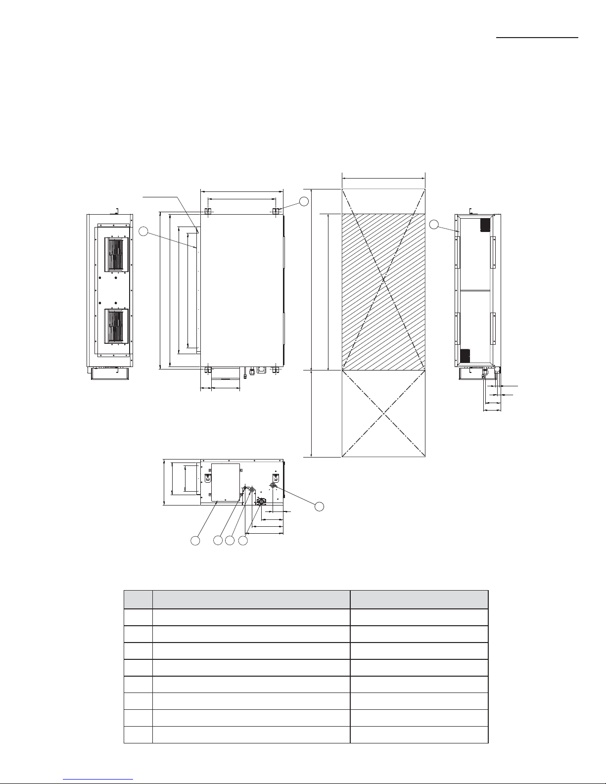
No. Name Description
1 Liquid pipe connection ø9.52
(3/8”)
2 Gas pipe connection ø15.88
(5/8”)
3 Drain pipe connection
3/4"(ODØ1.05"(26.67))
4 Drain pipe connection (Option drain pump)
3/4"(ODØ1.05"(26.67))
5 Power supply/Communication connection --
6 Power supply connection --
7 Air discharge grille flange --
8 Hook ø9.52(
3/8” )
or M10
AM030/036/048FNLD777
15.9(0.63'')
4290=1160(45.67'')
(3.27'')
83
2
88=176
(6.93'')
(0.39'')
10
1338(52.68'') Suspension position
690(27.17'')
477(18.78'') Suspension position
12100=1200(47.24'')
1260(49.61'') Air outlet duct flange
1300(51.18'')
32(1.26'')-ø3.2(0.13'') Hole
All around
Discharge side Suction side
295(11.61'')
247.6(9.75'')
2
100=200
(7.87'')
186(7.32'')
250(9.84'')
337(13.27'')
18(0.71'')
29(1.14'')
28(1.1'') 28(1.1'')
OD32(1.26'')
115.5(4.55'')
145.5(5.73'')
740(29.13'')
1300(51.18'')
1400(55.12'')
500(19.69'')
Unit : mm(inch)
11
ENGLISH
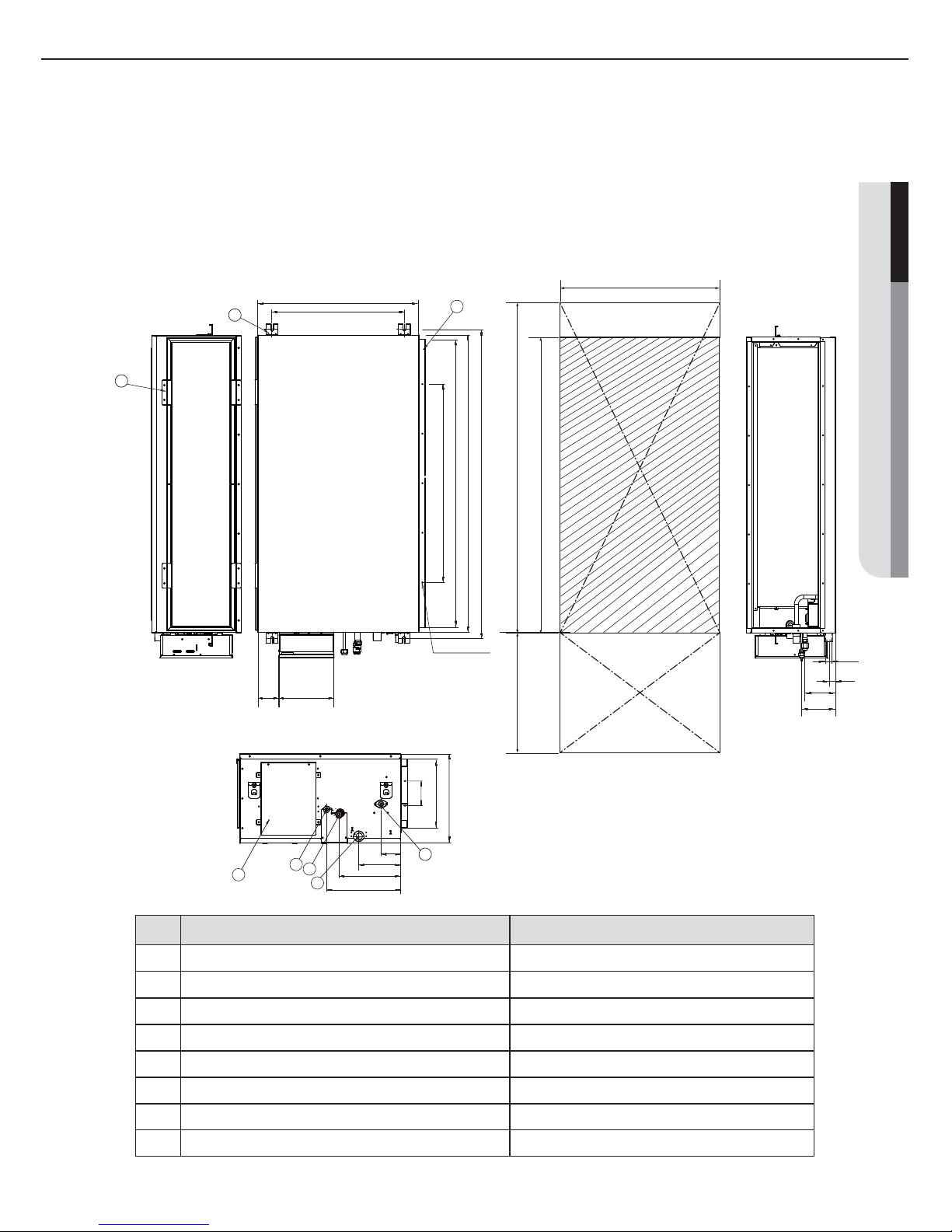
AM018/024FNMD777
No. Name Description
1 Liquid pipe connection
601866:ø6.35(1/4") ,602466:ø9.52(3/8")
2 Gas pipe connection
601866:ø12.7(1/2") ,602466:ø15.88(5/8")
3 Drain pipe connection
3/4"(ODØ1.05"(26.67))
4 Drain pipe connection (Option drain pump)
3/4"(ODØ1.05"(26.67))
5 Power supply/Communication connection --
6 Air discharge grille flange --
7 Suction flange --
8 Hook ø9.52(
3/8” )
or M10
76(2.99”)
132(5.19”)
139(5.47)
480(18.90")
397(15.63")(Suspension position)
260(10.23”)
185(7.28)
90(3.54)
936(36.85")(Suspension position)
900(35.43")
844(33.23")(Air outlet duct flange)
135x5=675(26.57")
12(0.47")
77(3.00")
117(4.61")
6
8
7
5 4
3
2
1
530(20.87")
900(35.43")
1000(39.37")500(19.68")
97(3.82")
87(3.43”)
222(8.74")
Discharge side
Suction side
Unit : mm(inch)
12
A
Selecting the installation location
AM030/036FNMD777
No. Name Description
1 Liquid pipe connection ø9.52
(3/8”)
2 Gas pipe connection ø15.88
(5/8”)
3 Drain pipe connection
3/4"(ODØ1.05"(26.67))
4 Drain pipe connection (Option drain pump)
3/4"(ODØ1.05"(26.67))
5 Power supply/Communication connection --
6 Air discharge grille flange --
7 Suction flange --
8 Hook ø9.52(
3/8” )
or M10
2
1
3
4
5
6
7
8
397(15.63'')(Suspension position)
Suction side
Discharge side
1186(46.69'')(Suspension position)
1150(45.28'')
902(35.51'')(Air outlet duct flange)
135×6=810(31.89'')
222(8.74'')
82
(3.23'')
137
(5.39'')
149
(5.87'')
480(18.90'')
27(1.06'')
107(4.21'')
157
(6.18'')
320(12.60'')
229(9.02'')
125(4.92'')
87
(3.43'')
1250(49.21’’)
1150(45.28’’)
500(19.69’’)
530(20.87’’)
Unit : mm(inch)
13
ENGLISH
8
54
2
1
3
7
6
AM007/009/012/015/018JNMD777
AM006JNMP777
(Drain pump built-in)
No. Name Description
1 Liquid pipe connection ø6.35
(1/4”)
2 Gas pipe connection ø12.70
(1/2”)
3 Drain pipe connection(Without drain pump)
3/4"(ODØ1.05"(26.67))
4 Drain pipe connection(With drain pump)
3/4"(ODØ1.05"(26.67))
5 Power supply/Communication connection --
6 Air discharge grille flange --
7 Suction flange --
8 Hook ø9.52(
3/8” )
or M10
Suction side
Discharge side
1186(46.69'')(Suspension position)
1150(45.28'')
1000(39.37'')(Air outlet duct flange)
6×150=900(35.43'')
Unit : mm(inch)
397(15.63'')(Suspension position)
480(18.90'')
530(20.87’’)
1250(49.21’’)
1150(45.28’’)
222(8.74'')
87
(3.43'')
500(19.69’’)
27(1.06'')
107(4.21'')
157(6.18'')
320(12.60'')
252(9.92'')
100(43.94'')
82(3.23'')
137(5.39'')
149(5.87'')
14
A
No. Name Description
1 Liquid pipe connection ø9.52
(3/8”)
2 Gas pipe connection ø15.88
(5/8”)
3 Drain pipe connection
3/4"(ODØ1.05"(26.67))
4 Drain pipe connection (Option drain pump)
3/4"(ODØ1.05"(26.67))
5 Power supply/Communication connection --
6 Air discharge grille flange --
7 Suction flange --
8 Hook ø9.52(
3/8” )
or M10
AM048FNMD 777
AM036/048FNHD 777
Unit : mm(inch)
7
8
6
4
3
2
1
5
534(21.02'') (Suspension position)
Suction sideDischarge side
360(14.17'')
253(9.96'')
(Air outlet duct flange)
2×100=200
(7.87'')
80(3.15'')
170(6.69'')
244(9.61'')
299(11.77'')
OD32(1.26'')
28(1.10'')
121(4.76'')
137(5.39'')
20(0.79'')-ø3.2(0.13'')hole
(All around)
1236(48.66'') (Suspension position)
1200(47.24'')
1000(39.37'') (Air outlet duct flange)
6×150=900(35.43'')
222(8.74'')
86
(3.39'')
1300(51.18’’)
1200(47.24’’)
500(19.69’’)
700(27.56’’)
650(25.59’’)
Selecting the installation location
15
ENGLISH
No. Name Description
1 Liquid pipe connection
ø9.52
(3/8”) (
7018JNMP7: ø6.35
(1/4”))
2 Gas pipe connection
ø15.88
(5/8”) (
7018JNMP7: ø12.70
(1/2”))
3 Drain pipe connection(Without drain pump)
3/4"(ODØ1.05"(26.67))
4 Drain pipe connection(With drain pump)
3/4"(ODØ1.05"(26.67))
5 Power supply/Communication connection --
6 Air discharge grille flange --
7 Suction flange --
8 Hook ø9.52(
3/8” )
or M10
AM024/027/030/036/048/054JNHD 777
AM018/028/042JNMP 777
(Drain pump built-in)
Unit : mm(inch)
7
6
8
5
4
1
2
3
534(21.02'') (Suspension position)
Suction side
1236(48.66'') (Suspension position)
1200(47.24'')
1162(45.75'') (Air outlet duct flange)
4×200=800(31.50'')
650(25.59’’)
700(27.56’’)
1300(51.18’’)
1200(47.24’’)
500(19.69’’)
Discharge side
222(8.74'')
86
(3.39'')
80(3.15'')
170(6.69'')
244(9.61'')
299(11.77'')
360(14.17'')
278(10.94'')
(Air outlet duct flange)
2×100=200
(7.87'')
20(0.79'')-ø3.2(0.13'')hole
(All around)
OD32(1.26'')
28(1.10'')
121(4.76'')
137(5.39'')
16
A
Selecting the installation location
No. Name Description
1 Liquid pipe connection ø1/4"(6.35)
2 Gas pipe connection ø1/2"(12.70)
3 Drain pipe connection 3/4"(ODØ1.05"(26.67))
4 Power supply connection
5 Air discharge flange
6 Air filter
7 Hook M8~M10
Unit : inch(mm)
7.28(185)
6.22(158)
5.75(146)
27.56(700)
7x3.937=27.56(7x100=700)
32.17(817)
33.46(850)
22-ø0.13(3.2)
35.43(900)
23.78(604)
27.56(700)
19.69(500)
33.46(850)
37.40(950)
8.66(220)
2x3.543=7.09(2x90=180)
9.84(250)
8.39(213)
4.92(125)
13.39(340)
Inspection hole
(Air outlet duct flange)
(Suspension position)
Discharge side Suction side
hole
(Air around)
(Suspension position)
AM007/009/012/015/018MNMD 777
(Drain pump built-in)
17
ENGLISH
Unit : inch(mm)
No. Name Description
1 Liquid pipe connection ø3/8"(9.52)
2 Gas pipe connection ø5/8"(15.88)
3 Drain pipe connection 3/4"(ODØ1.05"(26.67))
4 Power supply connection
5 Air discharge flange
6 Air filter
7 Hook M8~M10
7.28(185)
6.22(158)
5.83(148)
27.56(700)
23.78(604)
11x3.937=43.31(11x100=1100)
45.94(1167)
47.24(1200)
30-ø0.13(3.2)
49.21(1250)
27.56(700)
19.69(500)
47.24(1200)
51.18(1300)
8.66(220)
2x3.543=7.09(2x90=180)
9.84(250)
8.39(213)
4.92(125)
13.39(340)
Inspection hole
(Air outlet duct flange)
(Suspension position)
Discharge side
Suction side
hole
(Air around)
(Suspension position)
AM024/027/030MNHD 777
(Drain pump built-in)
 Loading...