

Page 1
Air conditioner
User manual
AM
777FN7D77
/ AM
777
JNM77 / AM
777MN7D77
ŷ Thank you for purchasing this Samsung air conditioner.
ŷ Before operating this unit, please read this user manual carefully and retain it for future
reference.
Page 2

Page 3
2
A
Contents
Safety precautions ......................................................................................................................................................3
Accessories ....................................................................................................................................................................5
Selecting the installation location ..........................................................................................................................6
Indoor unit installation .......................................................................................................................................... 20
Purging the unit ....................................................................................................................................................... 21
Connecting the refrigerant pipe .......................................................................................................................... 21
Cutting/aring the pipes ........................................................................................................................................ 23
Performing leak test & insulation ........................................................................................................................ 24
Drain pipe and drain hose installation ............................................................................................................... 26
Wiring work ............................................................................................................................................................... 30
Setting an indoor unit address and installation option ................................................................................. 33
Setting temperature control of discharge air ................................................................................................... 44
Final check and trial operation ............................................................................................................................. 44
Providing information for user ............................................................................................................................. 45
Troubleshooting ....................................................................................................................................................... 45
Adjusting air ow ..................................................................................................................................................... 47
Extending the power cable ................................................................................................................................... 53
Page 4
3
A
ENGLISH
Safety precautions
(Carefully follow the precautions listed below because they are essential to guarantee the safety of the
equipment.)
WARNING
xAlways disconnect the air conditioner from the power supply before servicing it or
accessing its internal components.
x
Verify that installation and testing operations are performed by qualified personnel.
xVerify that the air conditioner is not installed in an easily accessible area.
GENERAL INFORMATION
X Carefully read the content of this manual before installing the air conditioner and store the manual in a safe place in
order to be able to use it as reference after installation.
X For maximum safety, installers should always carefully read the following warnings.
X Store the operation and installation manual in a safe location and remember to hand it over to the new owner if the
air conditioner is sold or transferred.
X This manual explains how to install an indoor unit with a split system with two SAMSUNG units. The use of other types
of units with different control systems may damage the units and invalidate the warranty. The manufacturer shall not
be responsible for damages arising from the use of non compliant units.
X
The manufacturer shall not be responsible for damage originating from unauthorized changes or the improper connection
of electric and hydraulic lines. Failure to comply with these instructions or to comply with the requirements set forth in the
“Operating limits” table, included in the manual, shall immediately invalidate the warranty.
X The air conditioner should be used only for the applications for which it has been designed: the indoor unit is not
suitable to be installed in areas used for laundry.
X Do not use the units if damaged. If problems occur, switch the unit off and disconnect it from the power supply.
X In order to prevent electric shocks, fires or injuries, always stop the unit, disable the protection switch and contact
SAMSUNG’s technical support if the unit produces smoke, if the power cable is hot or damaged or if the unit is very
noisy.
X Always remember to inspect the unit, electric connections, refrigerant tubes and protections regularly.
These operations should be performed by qualified personnel only.
X The unit contains moving parts, which should always be kept out of the reach of children.
X Do not attempt to repair, move, alter or reinstall the unit. If performed by unauthorized personnel, these operations
may cause electric shocks or fires.
X Do not place containers with liquids or other objects on the unit.
X
All the materials used for the manufacture and packaging of the air conditioner are recyclable.
X The packing material and exhaust batteries of the remote control(optional) must be disposed of in accordance with
current laws.
X The air conditioner contains a refrigerant that has to be disposed of as special waste. At the end of its life cycle, the air
conditioner must be disposed of in authorized centers or returned to the retailer so that it can be disposed of correctly
and safely.
INSTALLING THE UNIT
IMPORTANT: When installing the unit, always remember to connect first the refrigerant tubes, then the electrical lines.
Always disassemble the electric lines before the refrigerant tubes.
X Upon receipt, inspect the product to verify that it has not been damaged during transport. If the product appears
damaged, DO NOT INSTALL it and immediately report the damage to the carrier or retailer (if the installer or the
authorized technician has collected the material from the retailer.)
X After completing the installation, always carry out a functional test and provide the instructions on how to operate
the air conditioner to the user.
X Do not use the air conditioner in environments with hazardous substances or close to equipment that release free
flames to avoid the occurrence of fires, explosions or injuries.
X The air conditioner should be used only for the applications for which it has been designed: the indoor unit is not
suitable to be installed in areas used for laundry.
Page 5
4
A
X Our units must be installed in compliance with the spaces indicated in the installation manual to ensure either
accessibility from both sides or ability to perform routine maintenance and repairs. The units’ components must be
accessible and that can be disassembled in conditions of complete safety either for people or things.
For this reason, where it is not observed as indicated into the Installation Manual, the cost necessary to reach and repair
the unit (in safety, as required by current regulations in force) with slings, trucks, scaffolding or any other means of
elevation won’t be considered in-warranty and charged to end user.
POWER SUPPLY LINE, FUSE OR CIRCUIT BREAKER
X Always make sure that the power supply is compliant with current safety standards. Always install the air conditioner in
compliance with current local safety standards.
X Always verify that a suitable grounding connection is available.
X Verify that the voltage and frequency of the power supply comply with the specifications and that the installed power is
sufficient to ensure the operation of any other domestic appliance connected to the same electric lines.
X Always verify that the cut-off and protection switches are suitably dimensioned.
X Verify that the air conditioner is connected to the power supply in accordance with the instructions provided in the
wiring diagram included in the manual.
X Always verify that electric connections (cable entry, section of leads, protections…) are compliant with the electric
specifications and with the instructions provided in the wiring scheme. Always verify that all connections comply with
the standards applicable to the installation of air conditioners.
X Make sure that you earth the cables.
- Do not connect the earth wire to the gas pipe, water pipe, lighting rod or telephone wire.
If earthing is not complete, electric shock or fire may occur.
X
Install the circuit breaker.
- If the circuit breaker is not installed, electric shock or fire may occur.
X
Make sure that the condensed water dripping from the drain hose runs out properly and safely.
X Install the power cable and communication cable of the indoor and outdoor unit at least 1m
away from the electric appliance.
X
Install the indoor unit away from lighting apparatus using the ballast.
- If you use the wireless remote control, reception error may occur due to the ballast of the
lighting apparatus.
X
Do not install the air conditioner in following places.
- Place where there is mineral oil or arsenic acid.
Resin parts flame and the accessories may drop or water may leak.
The capacity of the heat exchanger may reduce or the air conditioner may be out of order.
- The place where corrosive gas such as sulfurous acid gas generates from the vent pipe or air
outlet.
The copper pipe or connection pipe may corrode and refrigerant may leak.
- The place where there is a machine that generates electromagnetic waves.
The air conditioner may not operate normally due to control system.
- The place where there is a danger of existing combustible gas, carbon fiber or flammable
dust.
The place where thinner or gasoline is handled.
Gas may leak and it may cause fire.
Safety precautions
Caution
Page 6
5
A
ENGLISH
Accessories
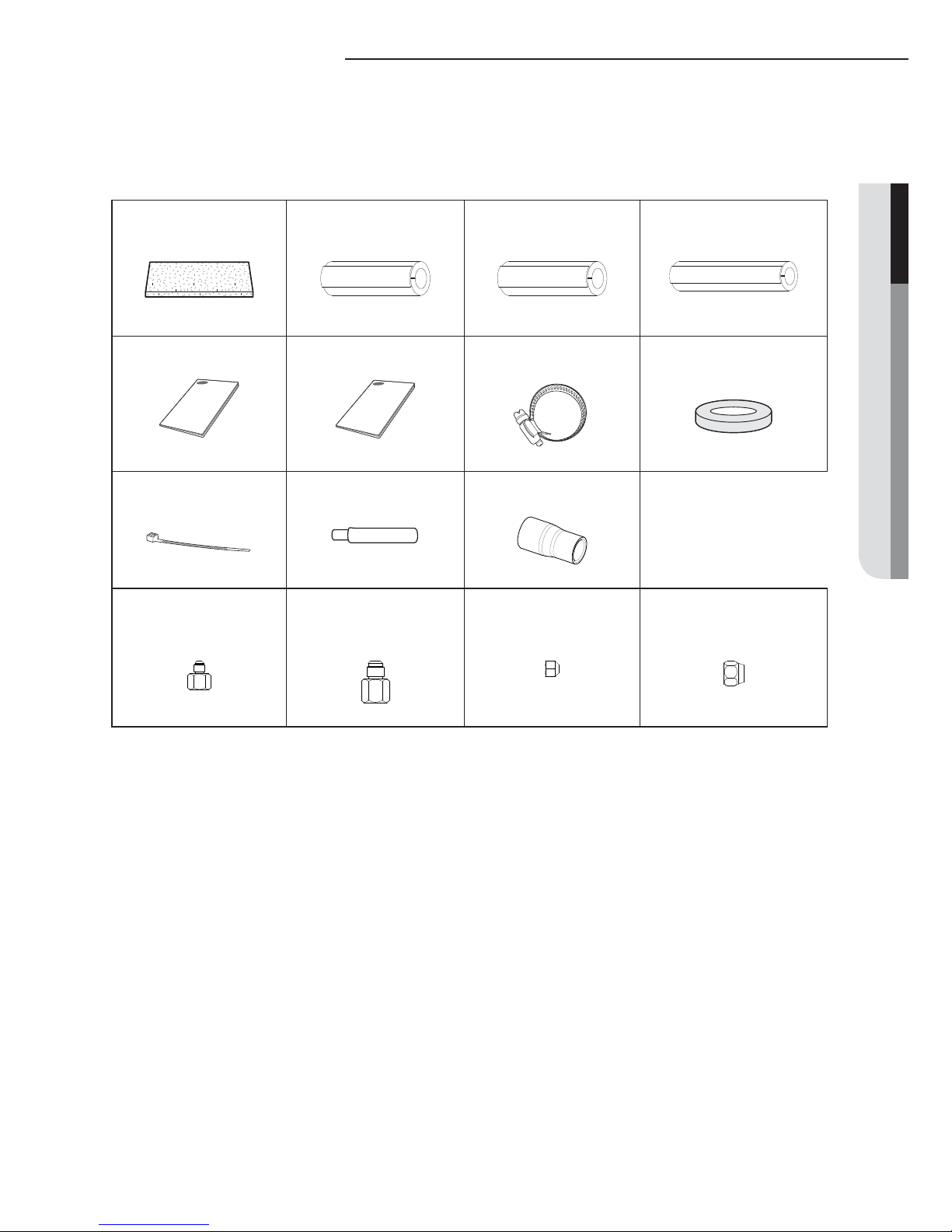
The following accessories are supplied with the indoor unit.
The type and quantity may differ depending on the specifications.
❈ Only AM018JNMPCH/AA include the last four accessories.
Insulation cover Thermal insulation A
(use for refrigerant pipe)
Thermal insulation B
(use for refrigerant pipe)
Thermal insulation
(use for drain hose)
User's manual Installation manual Flexible hose clamp Grommet
Cable tie Flexible hose Reducer
NIPPLE-CONNECTOR
(3/8"ĺ1/4")
NIPPLE-CONNECTOR
(5/8"ĺ1/2")
FASTENER-NUT FLARE
(1/4")
FASTENER-NUT FLARE
(1/2")
Page 7
6
A
Selecting the installation location
X There must be no obstacles near the air inlet and outlet.
X Install the indoor unit on a ceiling that can support its weight.
X Maintain sufficient clearance around the indoor unit.
X Make sure that the water dripping from the drain hose runs away correctly and safely.
X The indoor unit must be installed in this way, that they are out of public access. (Not touchable by the
users)
X
After connecting a chamber, insulate the connection part between the indoor unit and the chamber
with T0.39"(10) or thicker insulation. Otherwise, there can be air leak or dew from the connection part.
X Rigid wall without vibration.
X Where it is not exposed to direct sunshine.
X Where the air filter can be removed and cleaned easily.
z You must have 0.79inch (20mm) or more space between the ceiling and the bottom of indoor unit. Otherwise, the
noise from the vibration of indoor unit may bother the user.When the ceiling is under construction, the hole for
check-up must be made to take service, clean and repair the unit.
z It is possible to install the unit at an height of between 7.3~8.3ft(2.2~2.5m) from the ground, if the unit has a duct
with a well defined lenght (11.81inch(300mm) or more), to avoid fan motor blower contact.
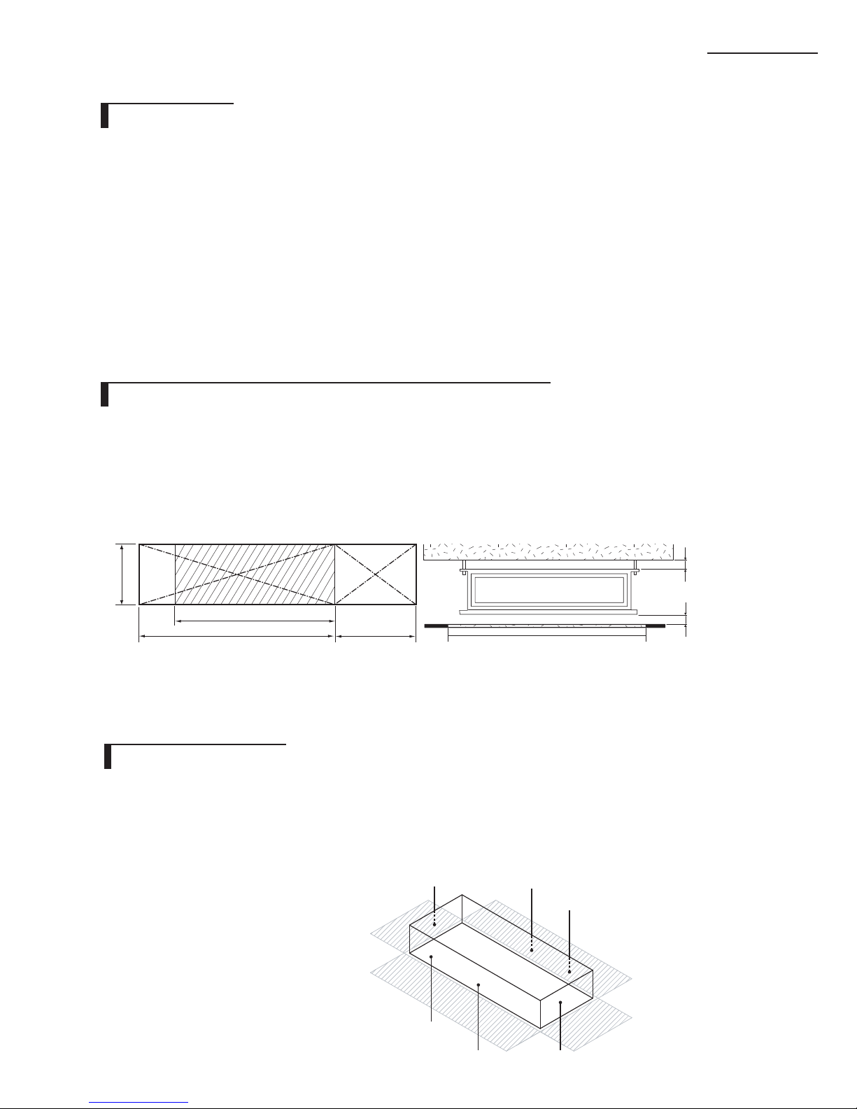
X
Construction Standard for Inspection Hole.
1) In case, the ceiling is textile, Inspection hole dose not need.
2) In case, the ceiling is plaster board, Inspection hole depends on Inside height of the ceiling.
a. Height is more than 1.64ft(0.5m) : Only “B” [Inspection for PBA] is applied.
b. Height is less than 1.64ft(0.5m) : Both “A” & ”B” are applied.
c. “A” & ”B” are inspection holes.
Unit Width(W)
“A”=W+
3.94inch(100mm)
“B”=19.7inch(500mm)
Unit Depth(D)
0.79inch(20mm)
or more
0.79inch(20mm)
or more
"
'SPOU
$
#
#BDL
%
X I nsulate the end of the pipe and some curved area by using separate insulator.
X I nsulate the discharge and suction part at the same time when you insulate connection duct.
X
If the humidity is over 80%, it is required to add 0.39inch(10mm) polyethylene foam or other
similar insulation to the indoor unit when installing belt or pipe type indoor unit on the ceiling.
Indoor Unit
Space requirements for installation & service
Insulation Guide
Page 8
7
ENGLISH
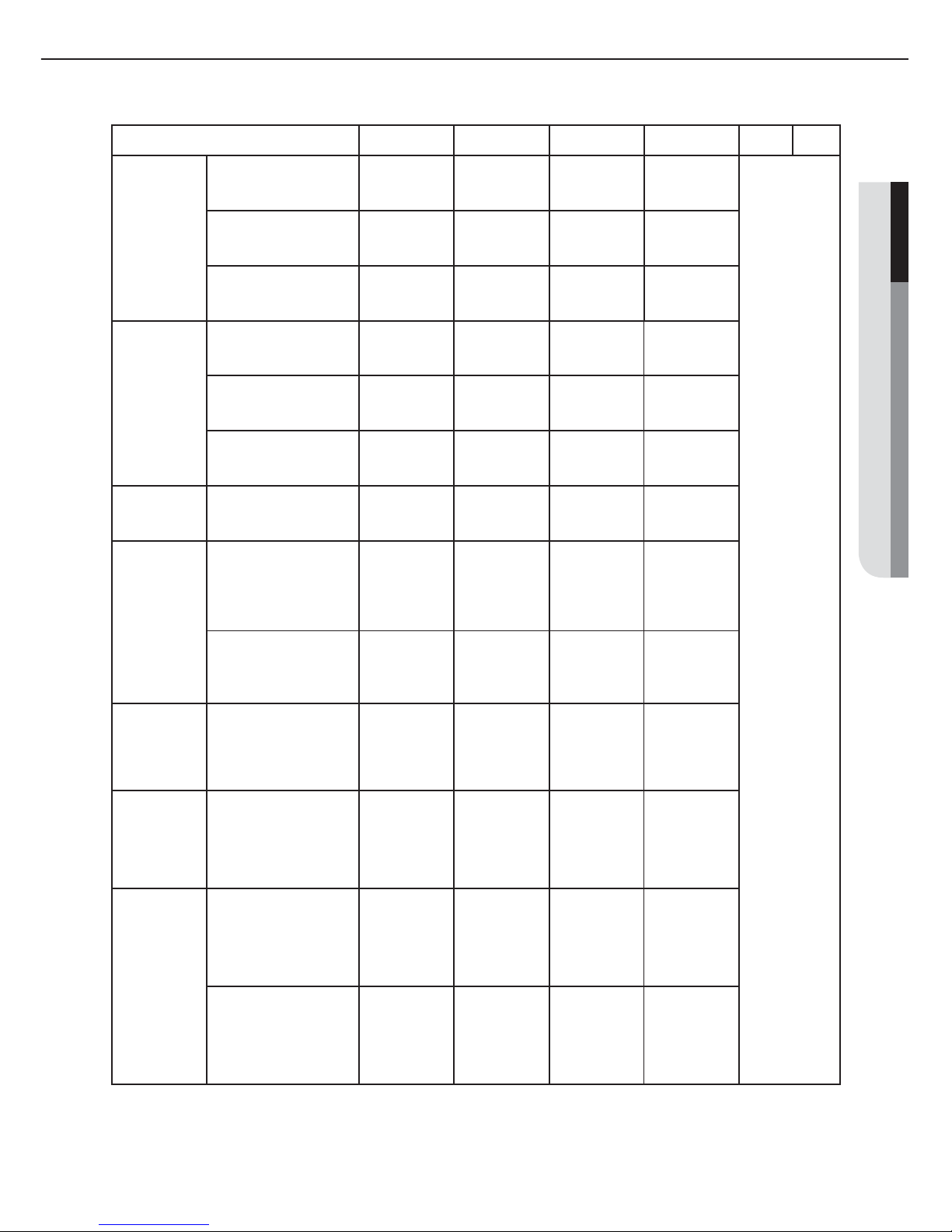
Thickness:more than 0.39inch (10mm)
Indoor unit A B C D Front Back
Slim Duct
AM7FNLD7
7
0077/70097/7012
7
35.43"x7.83"23.62"
(900x199x600)
35.43"×23.62"
(900x600)
35.43"×23.62"
(900x600)
23.62"×7.87"
(600x200)
23.62"×7.87"
(600x200)
Insulate the front
and back side
in proper size at
the same time
when insulating
the suction duct
and discharge
duct.
7
0187/7024
7
43.31"x7.83"x23.62"
(1100x199x600)
43.31"×23.62"
(1100x600)
43.31"×23.62"
(1100x600)
23.62"×7.87"
(600x200)
23.62"×7.87"
(600x200)
7
0307/70367/7048
7
51.18"x11.61"27.17"
(1300x295x690)
51.18"×27.17"
(1300x690)
51.18"×27.17"
(1300x690)
27.17"×11.81"
(690x300)
27.17"×11.81"
(690x300)
MSP Duct
AM7FNMD7
7
0187/7024
7
35.43"×18.90"x10.24"
(900x480x260)
35.43"×18.90"
(900x480)
35.43"×18.90"
(900x480)
18.90"×10.24"
(480x260)
18.90"×10.24"
(480x260)
7
0307/70367
45.28"×18.90"x12.60"
(1150x480x320)
45.28"×18.90"
(1150x480)
45.28"×18.90"
(1150x480)
18.90"×12.60"
(480x320)
18.90"×12.60"
(480x320)
7
048
7
47.24"x25.59"×14.17"
(1200x650x360)
47.24"×25.59"
(1200x650)
47.24"×25.59"
(1200x650)
25.59"×14.17"
(650x360)
25.59"×14.17"
(650x360)
HSP Duct
AM7FNHD7
7
0367/
7
048
7
47.24"x25.59"×14.17"
(1200x650x360)
47.24"×25.59"
(1200x650)
47.24"×25.59"
(1200x650)
25.59"×14.17"
(650x360)
25.59"×14.17"
(650x360)
MSP Duct
AM7JNMD7
AM7JNMP7
(Drain pump
built-in)
7D7:7
0077/70097/
7
0127/70157/70187
7P7:7
006
7
45.28"×18.90"x12.60"
(1150x480x320)
45.28"×18.90"
(1150x480)
45.28"×18.90"
(1150x480)
18.90"×12.60"
(480x320)
18.90"×12.60"
(480x320)
7P7:7
0187/70287/
7
042
7
47.24"x25.59"×14.17"
(1200x650x360)
47.24"×25.59"
(1200x650)
47.24"×25.59"
(1200x650)
25.59"×14.17"
(650x360)
25.59"×14.17"
(650x360)
HSP Duct
AM7JNHD7
(Drain pump
built-in)
7
0247/70277/70307/
7
0367/70487/7054
7
47.24"x25.59"×14.17"
(1200x650x360)
47.24"×25.59"
(1200x650)
47.24"×25.59"
(1200x650)
25.59"×14.17"
(650x360)
25.59"×14.17"
(650x360)
Duct S
AM7MNMD
7
(Drain pump
built-in)
7
0077/7009/70127/
0157/70187*
33.46x27.56x9.84
(850x700x250)
33.46"x27.56
"
(850x700)
33.46"x27.56
"
(850x700)
27.56"x9.84
"
(700x250)
27.56"x9.84
"
(700x250)
Duct S
AM7MNHD
7
(Drain pump
built-in)
7
0247/70277/7030
7
47.24x27.56x9.84
(1200x700x250)
47.24"x27.5
"
(1200x700)
47.24"x27.5
"
(1200x700)
27.56"x9.84
"
(700x250)
27.56"x9.84
"
(700x250)
7
0367/7048
7
51.18*27.56*11.81
(1300x700x300)
51.18"x27.56
"
(1300x700)
51.18"x27.56
"
(1300x700)
27.56"x11.81
"
(700x300)
27.56"x11.81
"
(700x300)
Page 9
8
Selecting the installation location
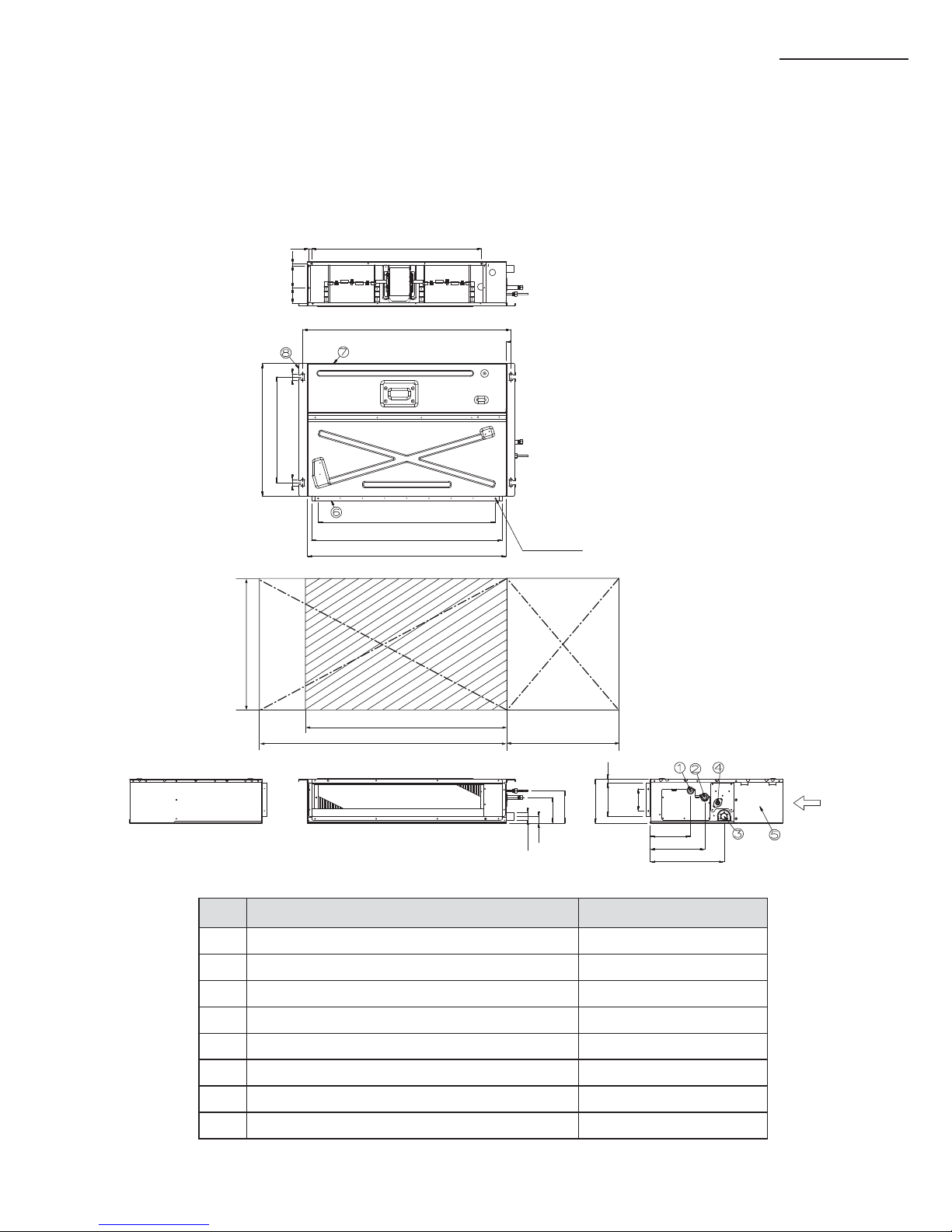
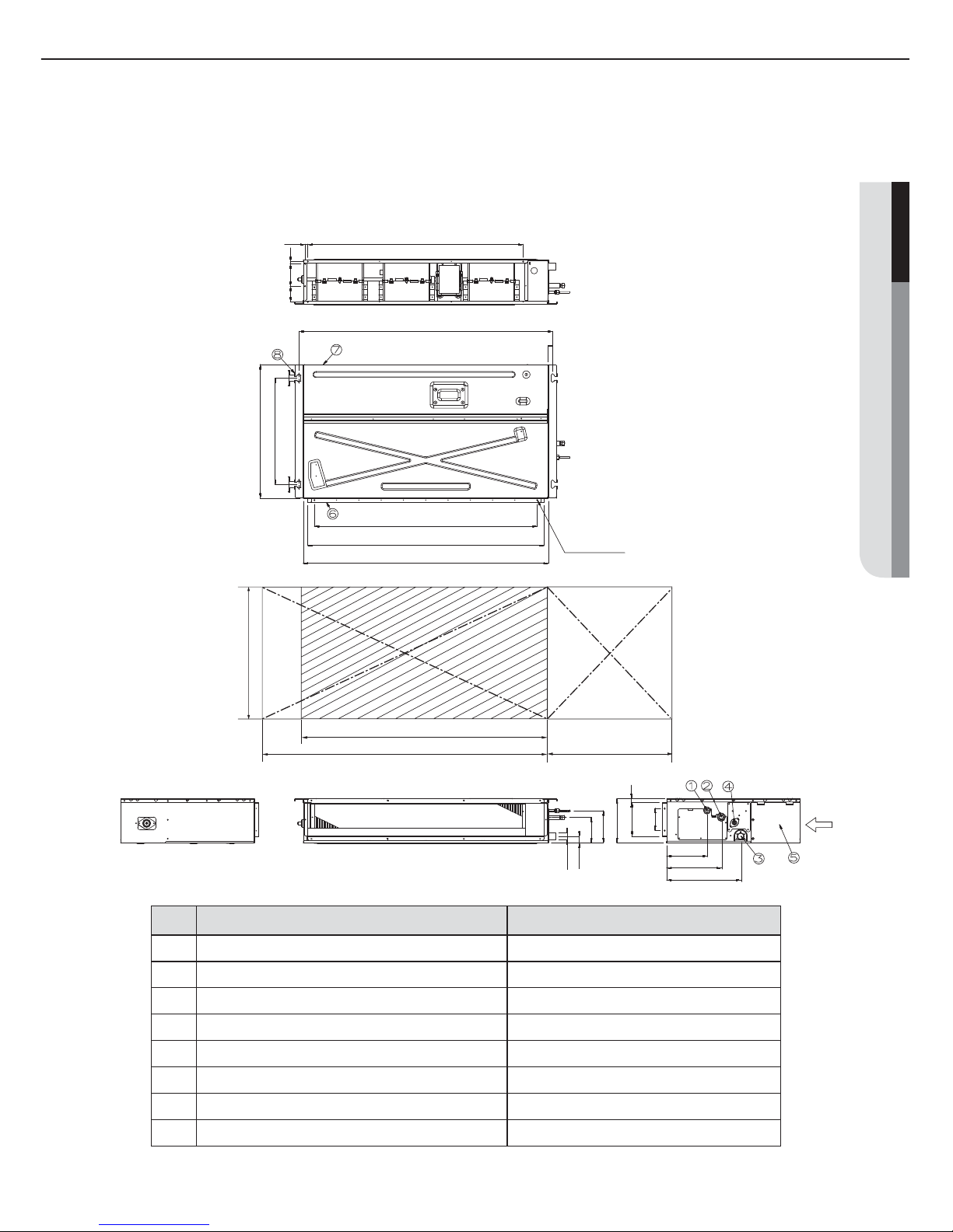
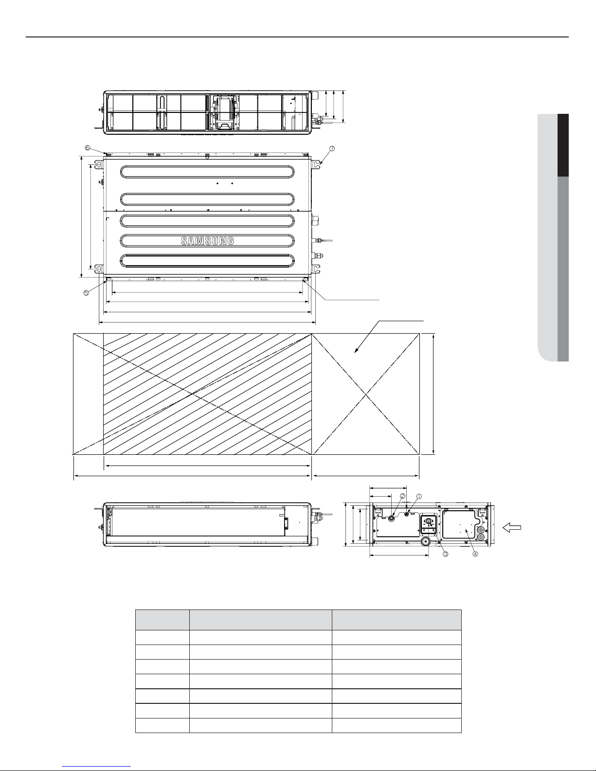
AM007/009/012FNLD777
No. Name Description
1 Liquid pipe connection ø6.35
(1/4”)
2 Gas pipe connection ø12.70
(1/2”)
3 Drain pipe connection
3/4"(ODØ1.05"(26.67))
4 Drain pipe connection (Option drain pump)
3/4"(ODØ1.05"(26.67))
5 Power supply/Communication connection --
6 Power supply connection --
7 Air discharge grille flange --
8 Hook ø9.52(
3/8” )
or M10
11.9(0.47'')
3256=768(30.14'')
(2.80'')
71
(3.94'')
100
(0.39'')
10
938.4(36.94'') Suspension position
600(23.62'')
477(18.78'') Suspension position
8100=800(31.50'')
860(33.86'') Air outlet duct flange
900(35.43'')
22(0.87'')-ø3.2(0.13'') Hole
28(1.1'')
All around
Discharge side Suction side
199(7.83'')
151.6(5.97'')
100(3.94'')
182(7.17'')
246(9.69'')
18(0.71'')
OD32(1.26'')
30.5(1.20'')
115.5(4.55'')
145.5(5.73'')
333(13.11'')
28(1.1'')
650(25.59'')
900(35.43'')
1000(39.37'')
500(19.69'')
Unit : mm(inch)
Page 10
9
ENGLISH
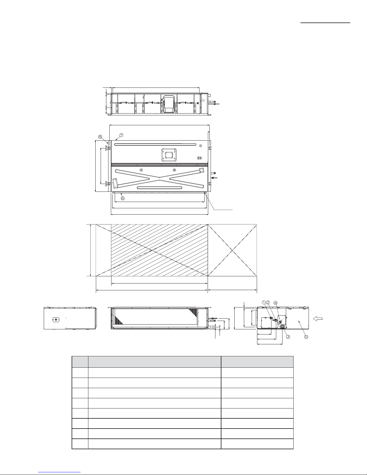
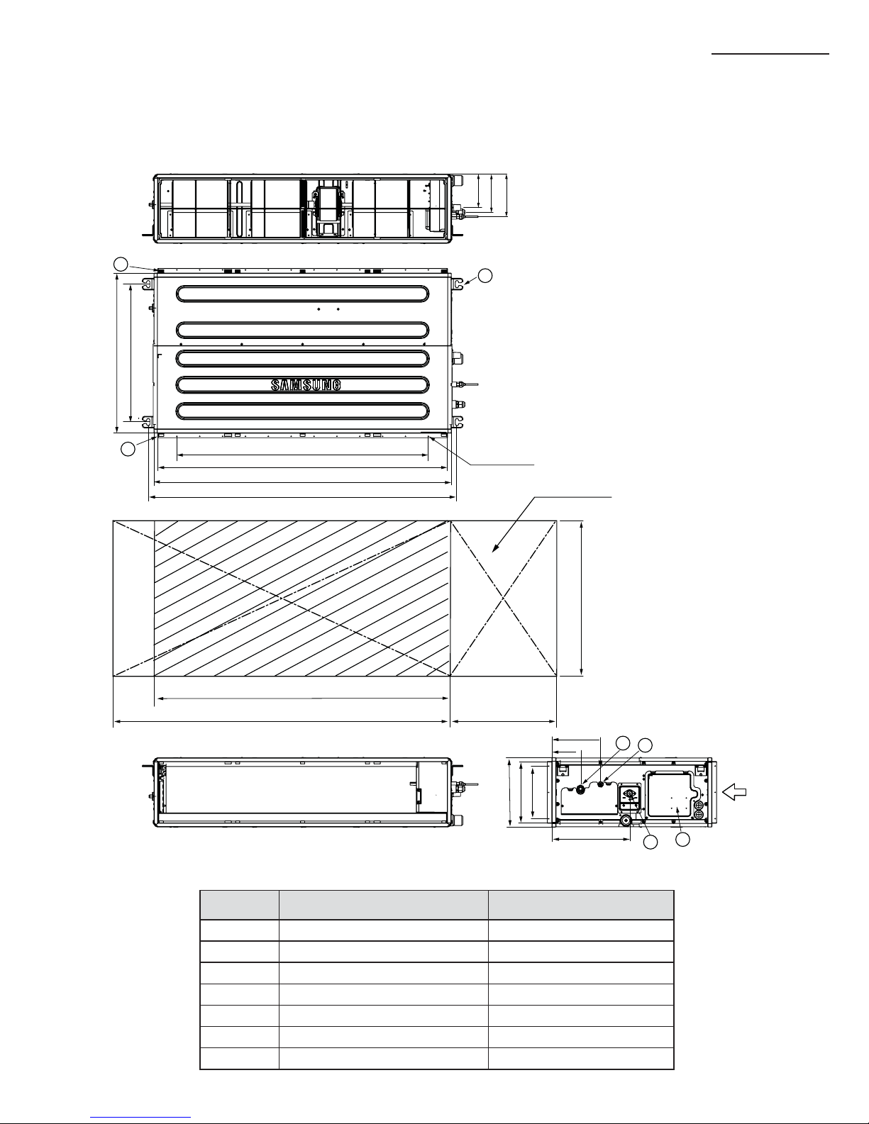
No. Name Description
1 Liquid pipe connection
601866:ø6.35(1/4") ,602466:ø9.52(3/8")
2 Gas pipe connection
601866:ø12.7(1/2") ,602466:ø15.88(5/8")
3 Drain pipe connection
3/4"(ODØ1.05"(26.67))
4 Drain pipe connection (Option drain pump)
3/4"(ODØ1.05"(26.67))
5 Power supply/Communication connection --
6 Power supply connection --
7 Air discharge grille flange --
8 Hook ø9.52(
3/8” )
or M10
AM018/024FNLD777
12.9(0.51'')
3322=966(38.03'')
1138(44.80'') Suspension position
477(18.78'') Suspension position
10100=1000(39.37'')
1060(41.73'') Air outlet duct flange
1100(43.31'')
26(1.02'')-ø3.2(0.13'') Hole
All around
Discharge side Suction side
(2.80'')
71
(3.94'')
100
(0.39'')
10
600(23.62'')
28(1.1'') 28(1.1'')
199(7.83'')
151.6(5.97'')
100(3.94'')
182(7.17'')
246(9.69'')
18(0.71'')
OD32(1.26'')
30.5(1.20'')
115.5(4.55'')
144.5(5.69'')
333(13.11'')
650(25.59'')
1100(43.31'')
1200(47.24'')
500(19.69'')
Unit : mm(inch)
Page 11
10
A
Selecting the installation location
No. Name Description
1 Liquid pipe connection ø9.52
(3/8”)
2 Gas pipe connection ø15.88
(5/8”)
3 Drain pipe connection
3/4"(ODØ1.05"(26.67))
4 Drain pipe connection (Option drain pump)
3/4"(ODØ1.05"(26.67))
5 Power supply/Communication connection --
6 Power supply connection --
7 Air discharge grille flange --
8 Hook ø9.52(
3/8” )
or M10
AM030/036/048FNLD777
15.9(0.63'')
4290=1160(45.67'')
(3.27'')
83
2
88=176
(6.93'')
(0.39'')
10
1338(52.68'') Suspension position
690(27.17'')
477(18.78'') Suspension position
12100=1200(47.24'')
1260(49.61'') Air outlet duct flange
1300(51.18'')
32(1.26'')-ø3.2(0.13'') Hole
All around
Discharge side Suction side
295(11.61'')
247.6(9.75'')
2
100=200
(7.87'')
186(7.32'')
250(9.84'')
337(13.27'')
18(0.71'')
29(1.14'')
28(1.1'') 28(1.1'')
OD32(1.26'')
115.5(4.55'')
145.5(5.73'')
740(29.13'')
1300(51.18'')
1400(55.12'')
500(19.69'')
Unit : mm(inch)
Page 12
11
ENGLISH
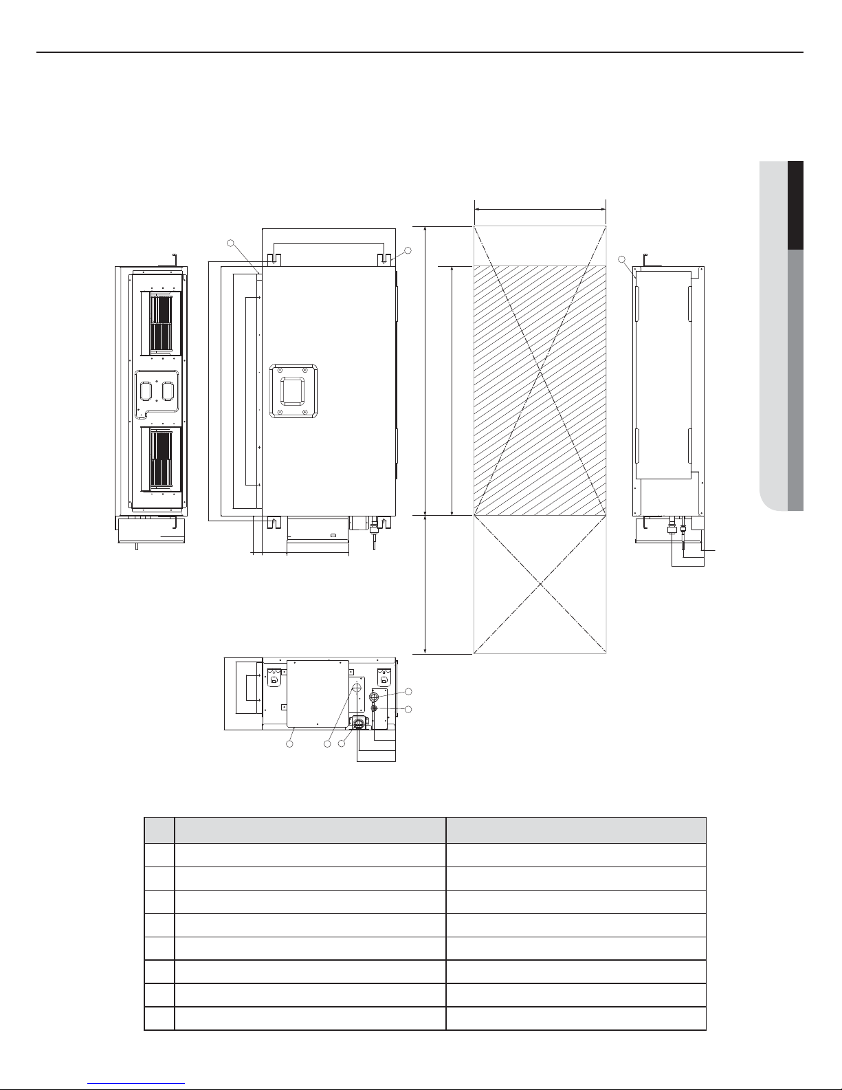
AM018/024FNMD777
No. Name Description
1 Liquid pipe connection
601866:ø6.35(1/4") ,602466:ø9.52(3/8")
2 Gas pipe connection
601866:ø12.7(1/2") ,602466:ø15.88(5/8")
3 Drain pipe connection
3/4"(ODØ1.05"(26.67))
4 Drain pipe connection (Option drain pump)
3/4"(ODØ1.05"(26.67))
5 Power supply/Communication connection --
6 Air discharge grille flange --
7 Suction flange --
8 Hook ø9.52(
3/8” )
or M10
76(2.99”)
132(5.19”)
139(5.47)
480(18.90")
397(15.63")(Suspension position)
260(10.23”)
185(7.28)
90(3.54)
936(36.85")(Suspension position)
900(35.43")
844(33.23")(Air outlet duct flange)
135x5=675(26.57")
12(0.47")
77(3.00")
117(4.61")
6
8
7
5 4
3
2
1
530(20.87")
900(35.43")
1000(39.37")500(19.68")
97(3.82")
87(3.43”)
222(8.74")
Discharge side
Suction side
Unit : mm(inch)
Page 13
12
A
Selecting the installation location
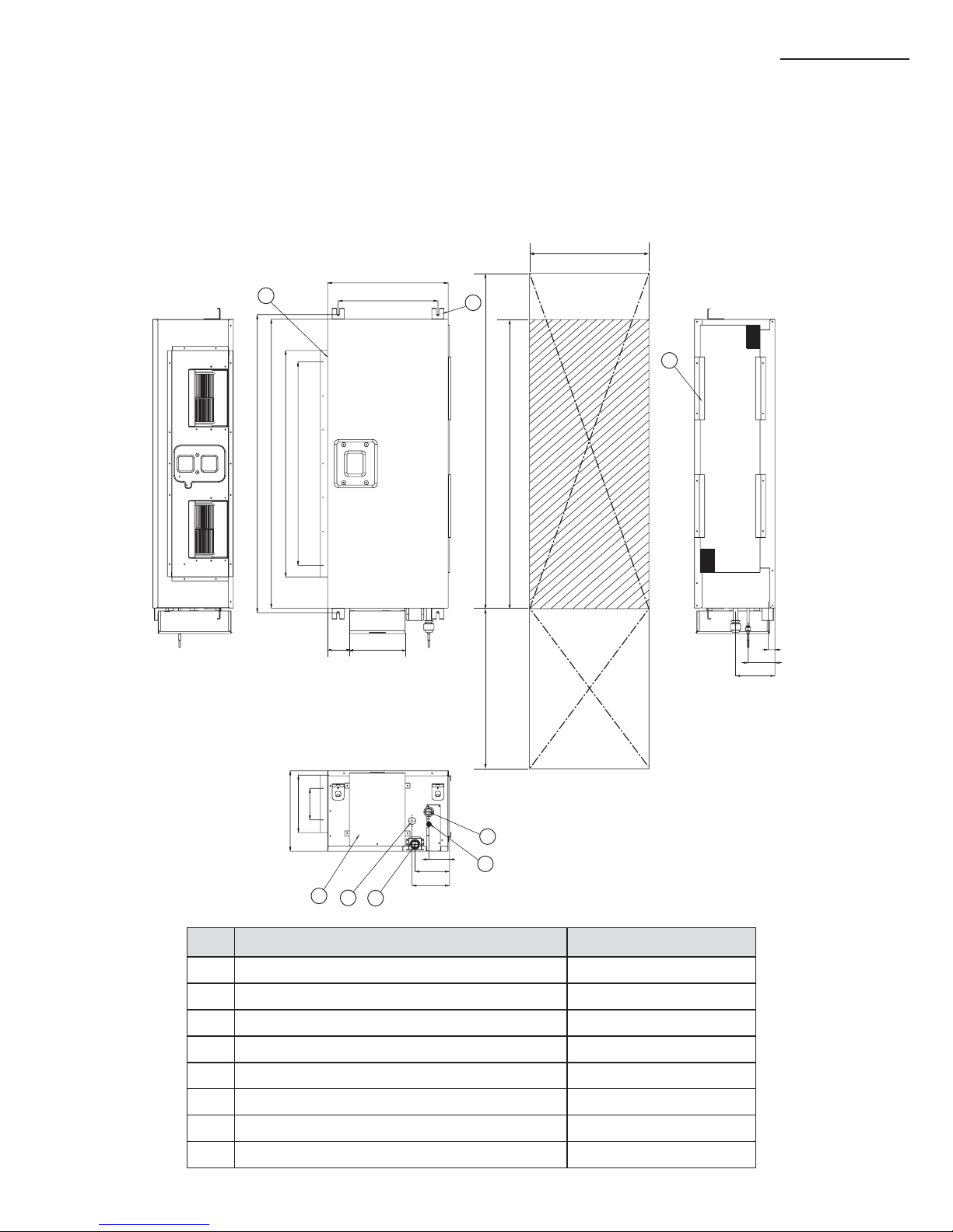
AM030/036FNMD777
No. Name Description
1 Liquid pipe connection ø9.52
(3/8”)
2 Gas pipe connection ø15.88
(5/8”)
3 Drain pipe connection
3/4"(ODØ1.05"(26.67))
4 Drain pipe connection (Option drain pump)
3/4"(ODØ1.05"(26.67))
5 Power supply/Communication connection --
6 Air discharge grille flange --
7 Suction flange --
8 Hook ø9.52(
3/8” )
or M10
2
1
3
4
5
6
7
8
397(15.63'')(Suspension position)
Suction side
Discharge side
1186(46.69'')(Suspension position)
1150(45.28'')
902(35.51'')(Air outlet duct flange)
135×6=810(31.89'')
222(8.74'')
82
(3.23'')
137
(5.39'')
149
(5.87'')
480(18.90'')
27(1.06'')
107(4.21'')
157
(6.18'')
320(12.60'')
229(9.02'')
125(4.92'')
87
(3.43'')
1250(49.21’’)
1150(45.28’’)
500(19.69’’)
530(20.87’’)
Unit : mm(inch)
Page 14
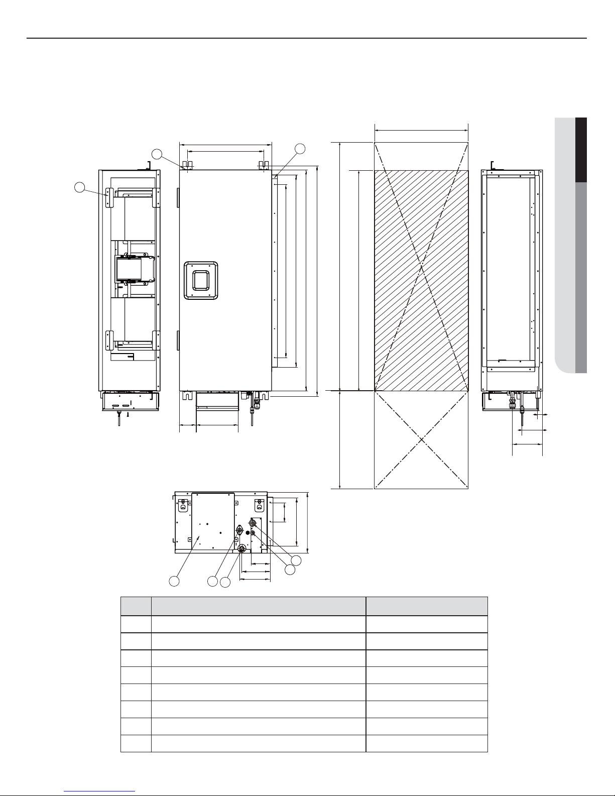
13
ENGLISH
8
54
2
1
3
7
6
AM007/009/012/015/018JNMD777
AM006JNMP777
(Drain pump built-in)
No. Name Description
1 Liquid pipe connection ø6.35
(1/4”)
2 Gas pipe connection ø12.70
(1/2”)
3 Drain pipe connection(Without drain pump)
3/4"(ODØ1.05"(26.67))
4 Drain pipe connection(With drain pump)
3/4"(ODØ1.05"(26.67))
5 Power supply/Communication connection --
6 Air discharge grille flange --
7 Suction flange --
8 Hook ø9.52(
3/8” )
or M10
Suction side
Discharge side
1186(46.69'')(Suspension position)
1150(45.28'')
1000(39.37'')(Air outlet duct flange)
6×150=900(35.43'')
Unit : mm(inch)
397(15.63'')(Suspension position)
480(18.90'')
530(20.87’’)
1250(49.21’’)
1150(45.28’’)
222(8.74'')
87
(3.43'')
500(19.69’’)
27(1.06'')
107(4.21'')
157(6.18'')
320(12.60'')
252(9.92'')
100(43.94'')
82(3.23'')
137(5.39'')
149(5.87'')
Page 15
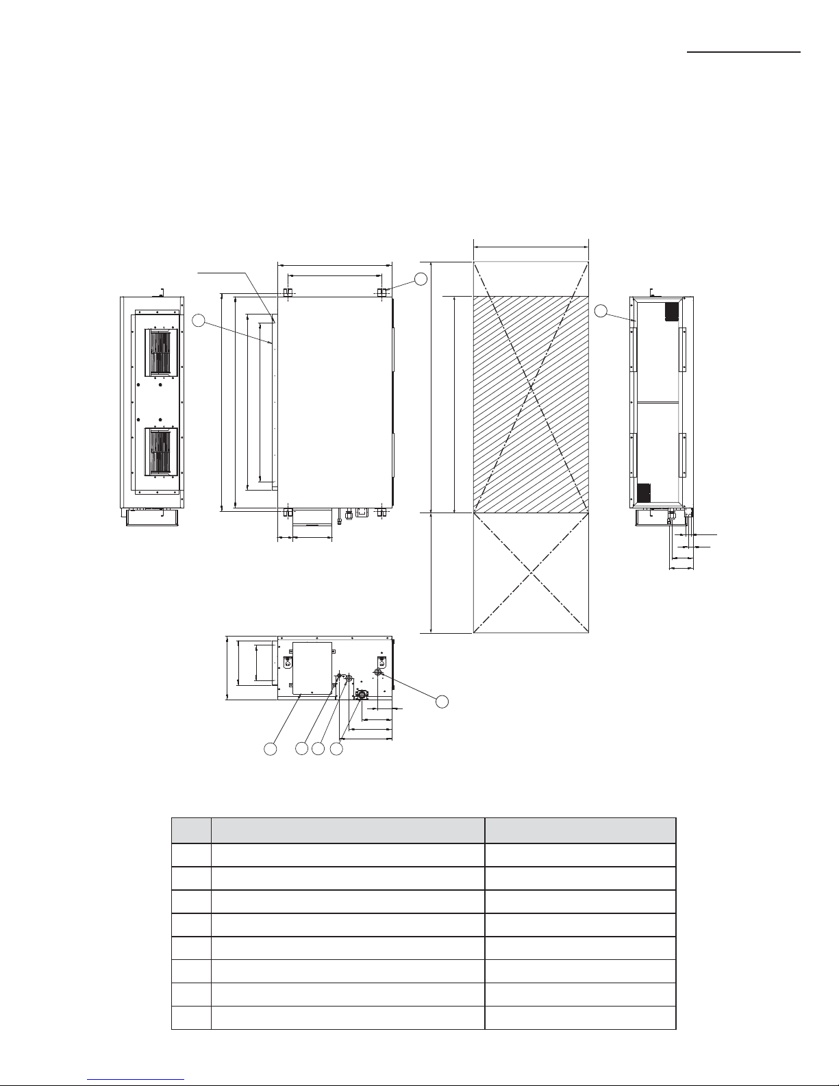
14
A
No. Name Description
1 Liquid pipe connection ø9.52
(3/8”)
2 Gas pipe connection ø15.88
(5/8”)
3 Drain pipe connection
3/4"(ODØ1.05"(26.67))
4 Drain pipe connection (Option drain pump)
3/4"(ODØ1.05"(26.67))
5 Power supply/Communication connection --
6 Air discharge grille flange --
7 Suction flange --
8 Hook ø9.52(
3/8” )
or M10
AM048FNMD 777
AM036/048FNHD 777
Unit : mm(inch)
7
8
6
4
3
2
1
5
534(21.02'') (Suspension position)
Suction sideDischarge side
360(14.17'')
253(9.96'')
(Air outlet duct flange)
2×100=200
(7.87'')
80(3.15'')
170(6.69'')
244(9.61'')
299(11.77'')
OD32(1.26'')
28(1.10'')
121(4.76'')
137(5.39'')
20(0.79'')-ø3.2(0.13'')hole
(All around)
1236(48.66'') (Suspension position)
1200(47.24'')
1000(39.37'') (Air outlet duct flange)
6×150=900(35.43'')
222(8.74'')
86
(3.39'')
1300(51.18’’)
1200(47.24’’)
500(19.69’’)
700(27.56’’)
650(25.59’’)
Selecting the installation location
Page 16
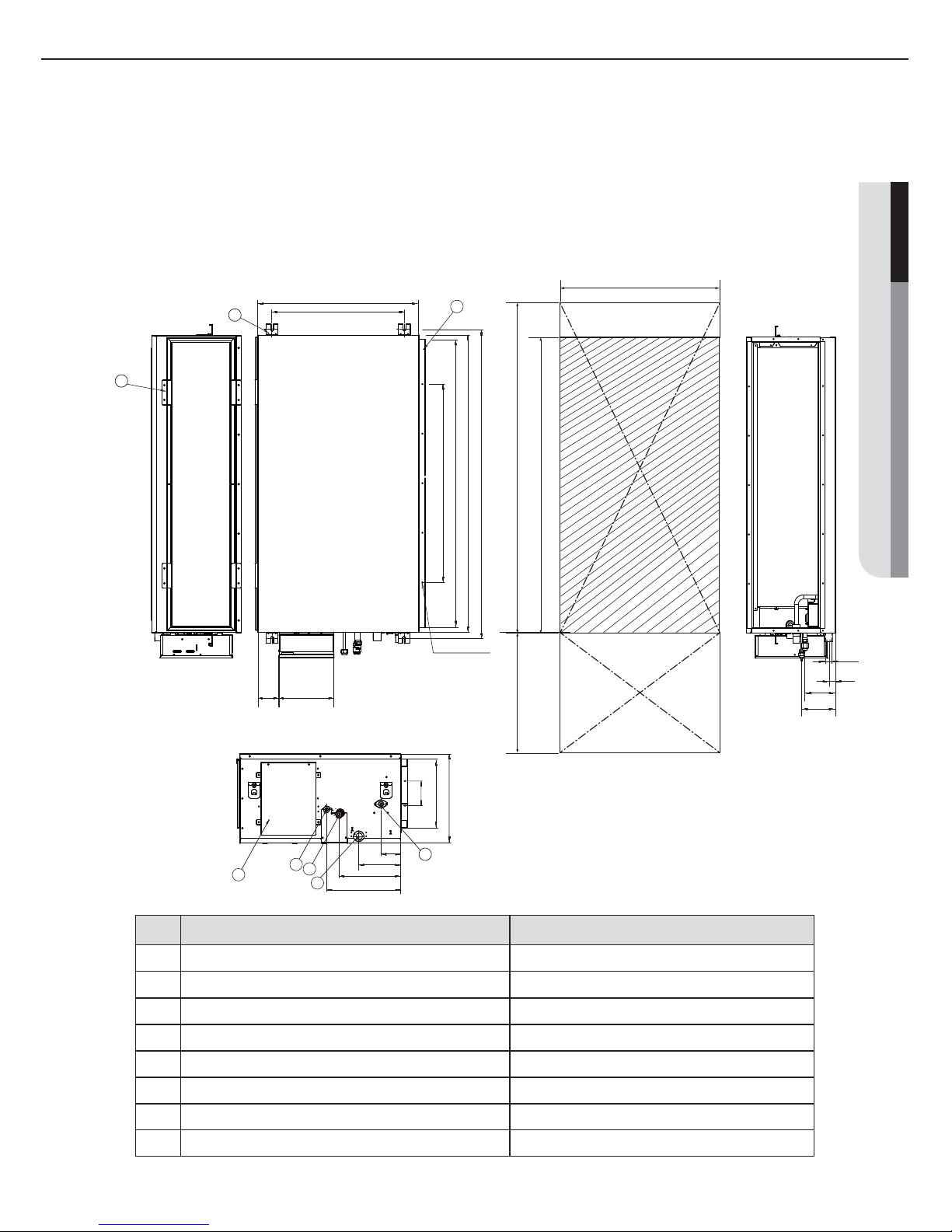
15
ENGLISH
No. Name Description
1 Liquid pipe connection
ø9.52
(3/8”) (
7018JNMP7: ø6.35
(1/4”))
2 Gas pipe connection
ø15.88
(5/8”) (
7018JNMP7: ø12.70
(1/2”))
3 Drain pipe connection(Without drain pump)
3/4"(ODØ1.05"(26.67))
4 Drain pipe connection(With drain pump)
3/4"(ODØ1.05"(26.67))
5 Power supply/Communication connection --
6 Air discharge grille flange --
7 Suction flange --
8 Hook ø9.52(
3/8” )
or M10
AM024/027/030/036/048/054JNHD 777
AM018/028/042JNMP 777
(Drain pump built-in)
Unit : mm(inch)
7
6
8
5
4
1
2
3
534(21.02'') (Suspension position)
Suction side
1236(48.66'') (Suspension position)
1200(47.24'')
1162(45.75'') (Air outlet duct flange)
4×200=800(31.50'')
650(25.59’’)
700(27.56’’)
1300(51.18’’)
1200(47.24’’)
500(19.69’’)
Discharge side
222(8.74'')
86
(3.39'')
80(3.15'')
170(6.69'')
244(9.61'')
299(11.77'')
360(14.17'')
278(10.94'')
(Air outlet duct flange)
2×100=200
(7.87'')
20(0.79'')-ø3.2(0.13'')hole
(All around)
OD32(1.26'')
28(1.10'')
121(4.76'')
137(5.39'')
Page 17
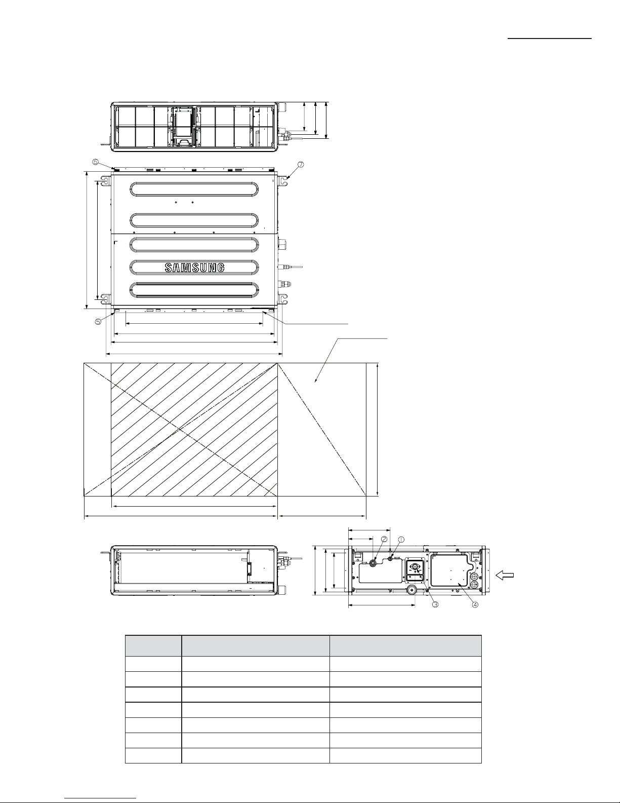
16
A
Selecting the installation location
No. Name Description
1 Liquid pipe connection ø1/4"(6.35)
2 Gas pipe connection ø1/2"(12.70)
3 Drain pipe connection 3/4"(ODØ1.05"(26.67))
4 Power supply connection
5 Air discharge flange
6 Air filter
7 Hook M8~M10
Unit : inch(mm)
7.28(185)
6.22(158)
5.75(146)
27.56(700)
7x3.937=27.56(7x100=700)
32.17(817)
33.46(850)
22-ø0.13(3.2)
35.43(900)
23.78(604)
27.56(700)
19.69(500)
33.46(850)
37.40(950)
8.66(220)
2x3.543=7.09(2x90=180)
9.84(250)
8.39(213)
4.92(125)
13.39(340)
Inspection hole
(Air outlet duct flange)
(Suspension position)
Discharge side Suction side
hole
(Air around)
(Suspension position)
AM007/009/012/015/018MNMD 777
(Drain pump built-in)
Page 18
17
ENGLISH
Unit : inch(mm)
No. Name Description
1 Liquid pipe connection ø3/8"(9.52)
2 Gas pipe connection ø5/8"(15.88)
3 Drain pipe connection 3/4"(ODØ1.05"(26.67))
4 Power supply connection
5 Air discharge flange
6 Air filter
7 Hook M8~M10
7.28(185)
6.22(158)
5.83(148)
27.56(700)
23.78(604)
11x3.937=43.31(11x100=1100)
45.94(1167)
47.24(1200)
30-ø0.13(3.2)
49.21(1250)
27.56(700)
19.69(500)
47.24(1200)
51.18(1300)
8.66(220)
2x3.543=7.09(2x90=180)
9.84(250)
8.39(213)
4.92(125)
13.39(340)
Inspection hole
(Air outlet duct flange)
(Suspension position)
Discharge side
Suction side
hole
(Air around)
(Suspension position)
AM024/027/030MNHD 777
(Drain pump built-in)
Page 19
18
A
19.69(500)
51.18(1300)
55.12(1400)
27.56(700)
7
7.28(185)
6.30(160)
5.75(146)
27.56(700)
23.78(604)
5
6
11x3.937=43.31(11x100=1100)
49.92(1268)
51.18(1300)
53.15(1350)
30-ø0.13(3.2)
10.63(270)
11.81(300)
8.39(213)
4.92(125)
13.39(340)
1
2
3
4
2x4.53=7.06(2x115=230)
Inspection hole
(Air outlet duct flange)
(Suspension position)
Discharge side
Suction side
hole
(Air around)
(Suspension position)
Unit : inch(mm)
No. Name Description
1 Liquid pipe connection ø3/8"(9.52)
2 Gas pipe connection ø5/8"(15.88)
3 Drain pipe connection 3/4"(ODØ1.05"(26.67))
4 Power supply connection
5 Air discharge flange
6 Air filter
7 Hook M8~M10
Selecting the installation location
AM036/048MNHD 777
(Drain pump built-in)
Page 20
19
A
ENGLISH
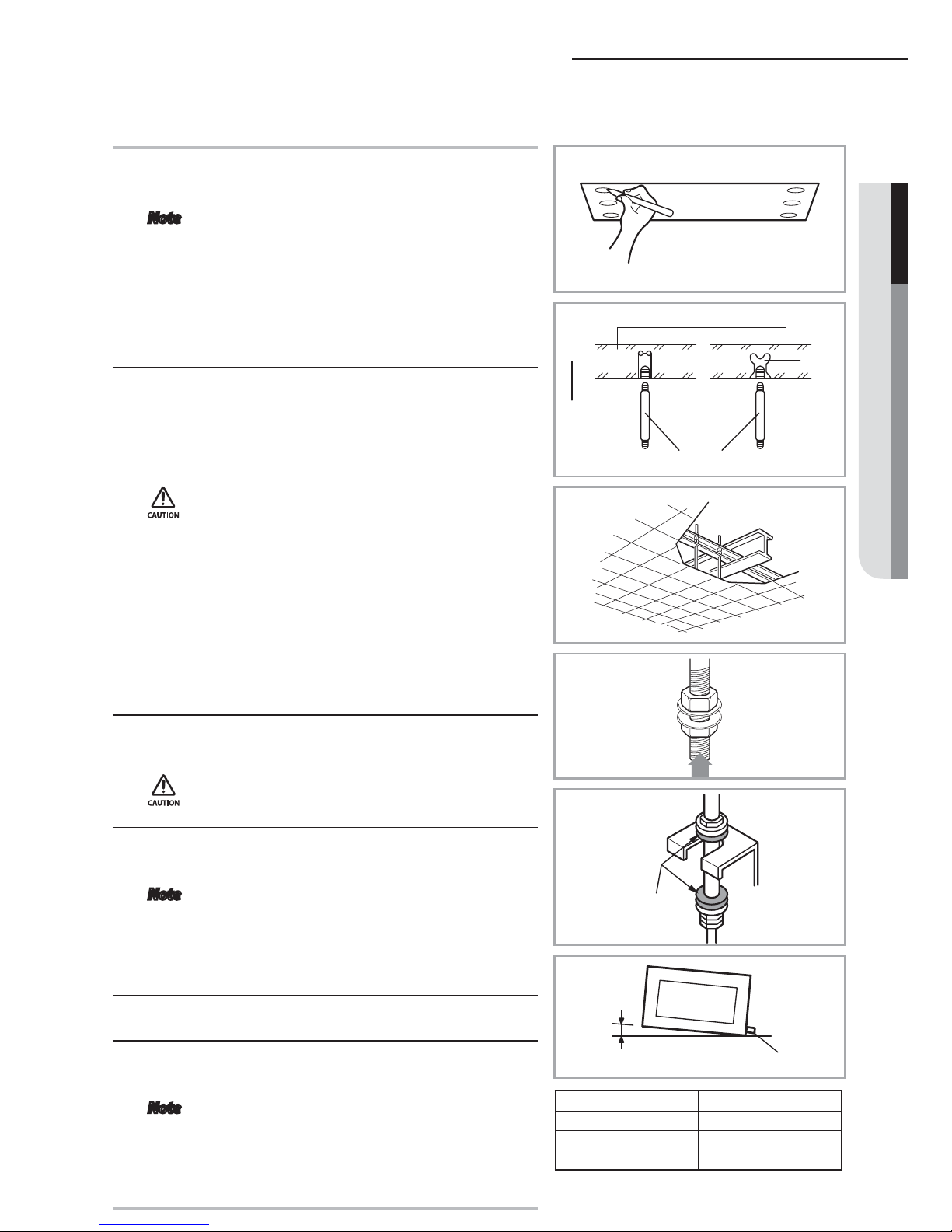
Indoor unit installation
Concrete
Suspension bolt(
ø9.52
(3/8”)
or M10)
Hole in anchor
Hole in plug
Insert
Drain hose port
A
Rubber
Ceiling support
It is recommended to install theY-joint before installing the
indoor unit.
1
Place the pattern sheet on the ceiling at the spot where
you want to install the indoor unit.
Note XSince the diagram is made of paper, it may
shrink or stretch slightly due to temperature
or humidity. For this reason, before drilling
the holes maintain the correct dimensions
between the markings.
X
Pattern sheet is supplied depending on the
model type.
2
Insert bolt anchors, use existing ceiling supports or
construct a suitable support as shown in figure.
3
Install the suspension bolts depending on the ceiling
type.
X
Ensure that the ceiling is strong enough to
support the weight of the indoor unit.
Before hanging the unit, test the strength of
each attached suspension bolt.
X
If the length of suspension bolt is more
than
4.92ft(1.5m)
, it is required to prevent vibra-
tion.
XIf this is not possible, create an opening on
the false ceiling in order to be able to use it
to perform the required operations on the
indoor unit.
4
Screw eight nuts to the suspension bolts making space
for hanging the indoor unit.
X
You must install the suspension bolts more
than four when installing the indoor unit.
5
Hang the indoor unit to the suspension bolts between
two nuts.
Note Piping must be laid and connected inside
the ceiling when suspending the unit. If the
ceiling is already constructed, lay the piping
into position for connection to the unit
before placing the unit inside the ceiling.
6
Screw the nuts to suspend the unit.
7
Adjust level of the unit by using measurement plate for
all 4 sides.
Note For proper drainage of condensate, give a
'A' slant to the left or right side of the unit
which will be connected with the drain hose,
as shown in the figure. Make a tilt when you
wish to install the drain pump, too.
Unit A
Slim Duct/Duct S
0.12inch (
3mm)
MSP Duct
HSP Duct
0.39inch (
10mm)
Page 21
20
A
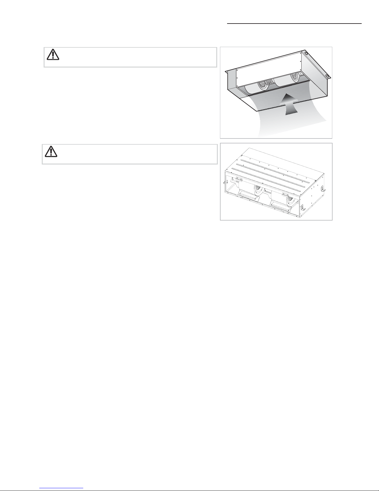
For HSP Duct (AM024/027/030/036/048JNHDCH),2 PadCushion should be removed before installing air conditioner.
Caution
Noise will increase 3~6 dB(A) when the air flow enters
from the bottom side (Only for Slim Duct Type product).
Caution
Air Flow
Indoor unit installation
Page 22
21
A
ENGLISH
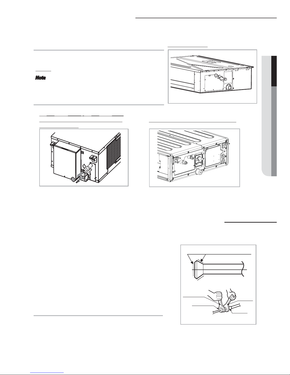
On delivery, the indoor unit is loaded with inert gas.
All this gas must therefore be purged before connecting the
assembly piping. To purge the inert gas, proceed as follows.
Unscrew the pinch pipe at the end of each refrigerant pipe.
Result: All inert gas escapes from the indoor unit.
Note To prevent dirt or foreign objects from getting
into the pipes during installation, do NOT remove
the pinch pipe completely until you are ready to
connect the piping.
K The designs and shape are subject to change
according to the model.
AM77FNLD777
AM77FNMD777/AM77FNHD777
AM77JNMD777/AM77JNHD777
AM77JNMP777
Purging the unit
AM77MNMD777/AM77MNHD777
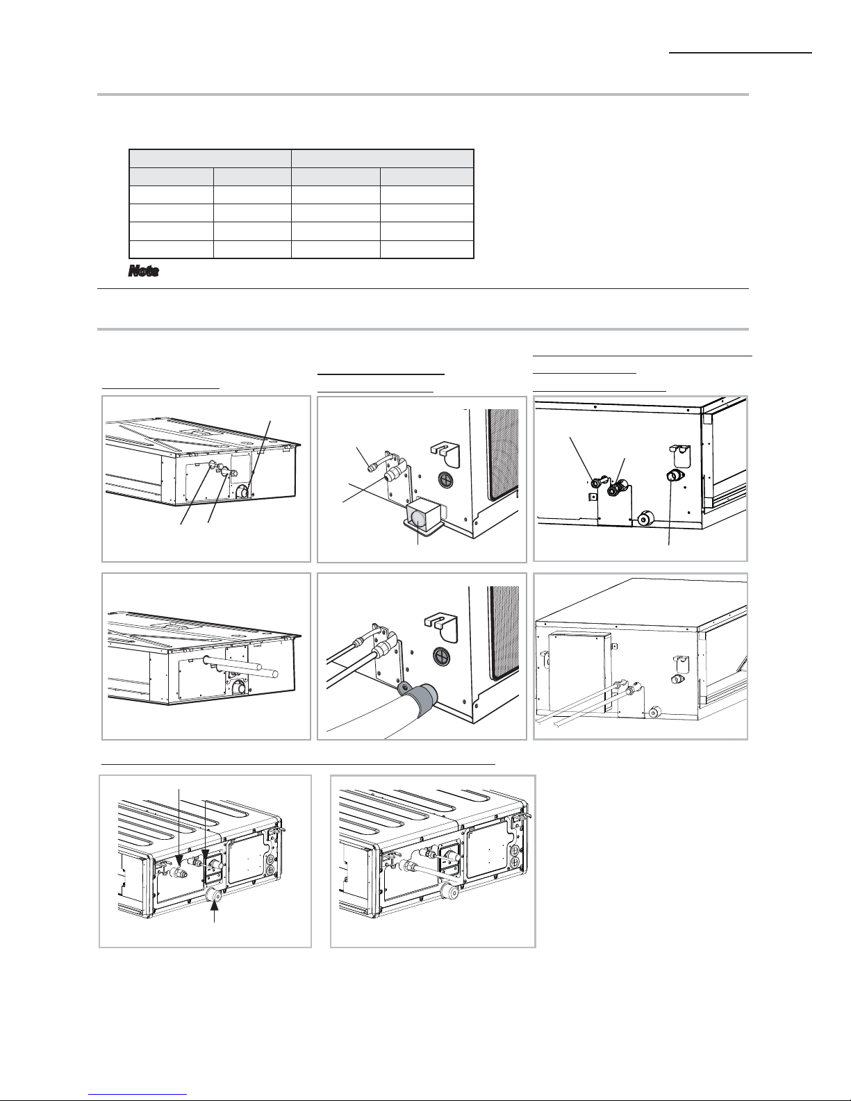
There are two refrigerant pipes of differing diameters:
X A smaller one for the liquid refrigerant
X A larger one for the gas refrigerant
X The inside of copper pipe must be clean & has no dust.
The connection procedure for the refrigerant pipes varies
according to the exit position of the pipes from the indoor unit,
as seen when facing the indoor in the “A” side.
X Liquid refrigerant port
X Gas refrigerant port
X Drain hose port
Refrigerant oil
Torque wrench
Flare nut
Union
Spanner
Connecting the refrigerant pipe
Page 23
22
A
Connecting the refrigerant pipe
1
Remove the pinch pipe on the pipes and connect the assembly pipes to each pipe, tightening the nuts, first
manually and then with a torque wrench, a spanner applying the following torque.
Outer Diameter
Torque
mm inch /tN MCGtGU
6.35 1/4 14~18 10.3~13.3
9.52 3/8 34~42 25.1~31.0
12.7 1/2 49~61 36.1~45.0
15.88 5/8 68~82 50.2~60.5
Note Must apply refrigerant oil on the flaring area to prevent a leak.
2
Be sure that there must be no crack or kink on the bended area.
K The designs and shape are subject to change according to the model.
A
Liquid refrigerant
port
Gas refrigerant port
Drain hose connection port
A
Gas
refrigerant port
Liquid refrigerant port
Drain hose connection port
AM77FNLD777
AM77FNMD777/
AM77FNHD777
AM77JNMD777/AM77JNHD777
AM77JNMP777
(Drain pump built-in)
Liquid refrigerant port
Gas
refrigerant port
Drain hose connection port
Drain hose connection port
Liquid refrigerant port
Gas refrigerant port
AM77MNMD777/AM77MNHD777(Drain pump built-in)
Page 24
23
A
ENGLISH
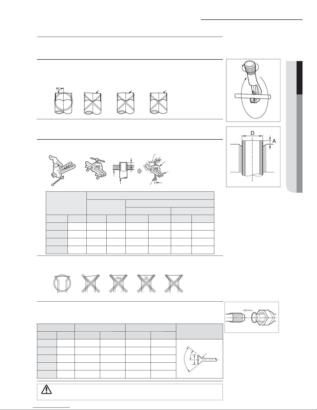
Cutting/aring the pipes
Inclined Damaged Surface Cracked Uneven Thickness
1
Make sure that you prepared the required tools.
(pipe cutter, reamer, flaring tool and pipe holder)
2
If you want to shorten the pipe, cut it using a pipe cutter ensuring that the
cut edge remains at 90° with the side of the pipe. There are some examples of
correctly and incorrectly cut edges below.
Oblique Rough Burr
3
To prevent a gas leak, remove all burrs at the cut edge of the pipe using a reamer.
4
Carry out flaring work using flaring tool as shown below.
Flaring tool
Clutch type Wing nut type
A
Die
Copper pipe
Yor k
Die
Copper
pipe
Flare nut
5
Check if you flared the pipe correctly. There are some examples of incorrectly
flared pipes below.
6
Align the pipes and tighten the flare nuts first manually and then with a torque
wrench, applying the following torque.
Outer diameter (D)
Depth of aring part (A)
Using aring tool
for R-410A
Using conventional aring tool
Clutch type Wing nut type
mm inch mm inch mm inch mm inch
6.35 1/4 0~0.5 0~0.02 1.0~1.5 0.04~0.06 1.5~2.0 0.06~0.08
9.52 3/8 0~0.5 0~0.02 1.0~1.5 0.04~0.06 1.5~2.0 0.06~0.08
12.70 1/2 0~0.5 0~0.02 1.0~1.5 0.04~0.06 1.5~2.0 0.06~0.08
15.88 5/8 0~0.5 0~0.02 1.0~1.5 0.04~0.06 1.5~2.0 0.06~0.08
Outer diameter Connection Torque Flare dimension
Flare shape
[mm(inch)]
mm inch N·m Ibf·ft mm inch
6.35 1/4 14~18 10.3~13.3 8.7~9.1 0.34~0.36
90° ±2°
45°
±2°
R 0.4~0.8
(0.016~0.032)
9.52 3/8 34~42 25.1~31.0 12.8~13.2 0.50~0.52
12.70 1/2 49~61 36.1~45.0 16.2~16.6 0.64~0.65
15.88 5/8 68~82 50.2~60.5 19.3~19.7 0.76~0.78
19.05 3/4 100~120 73.8~88.5 23.6~24.0 0.93~0.94
In case of needing brazing, you must work with Nitrogen gas blowing.
Caution
Page 25
24
A
Performing leak test & insulation
LEAK TEST WITH NITROGEN (before opening valves)
In order to detect basic refrigerant leaks, before recreating the vacuum and recirculating the R410A, it’s
responsible of installer to pressurize the whole system with nitrogen (using a pressure regulator) at a pressure
above 4.1MPa(594.7 psig) (gauge).
LEAK TEST WITH R410A (after opening valves)
Before opening valves, discharge all the nitrogen into the system and create vacuum. After opening valves
check leaks using a leak detector for refrigerant R410A.
K The designs and shape are subject to change according to the model.
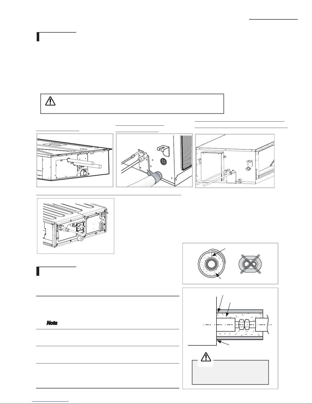
AM77FNLD777
AM77FNMD777/
AM77FNHD777
Leak test
Insulation
AM77JNMD777/AM77JNHD777
AM77JNMP777(Drain pump built-in)
No gap
NBR(T13.0(0.51") or thicker)
Insulation cover pipe
Indoor unit
Be sure to overlap
the insulation
Insulation pipe
Must fit tightly against body
without any gap.
Caution
Discharge all the nitrogen to create a vacuum and charge the system.
Caution
Once you have checked that there are no leaks in the system,
you can insulate the piping and hose.
1
To avoid condensation problems, place T13.0(0.51") or
thicker Acrylonitrile Butadien Rubber separately around
each refrigerant pipe.
Note Always make the seam of pipes face upwards.
2
Wind insulating tape around the pipes and drain hose
avoiding to compress the insulation too much.
3
inish wrapping insulating tape around the rest of the pipes
leading to the outdoor unit.
4
The pipes and electrical cables connecting the indoor unit
with the outdoor unit must be fixed to the wall with suitable
ducts.
AM77MNMD777/AM77MNHD777(Drain pump built-in)
Page 26
25
ENGLISH
5
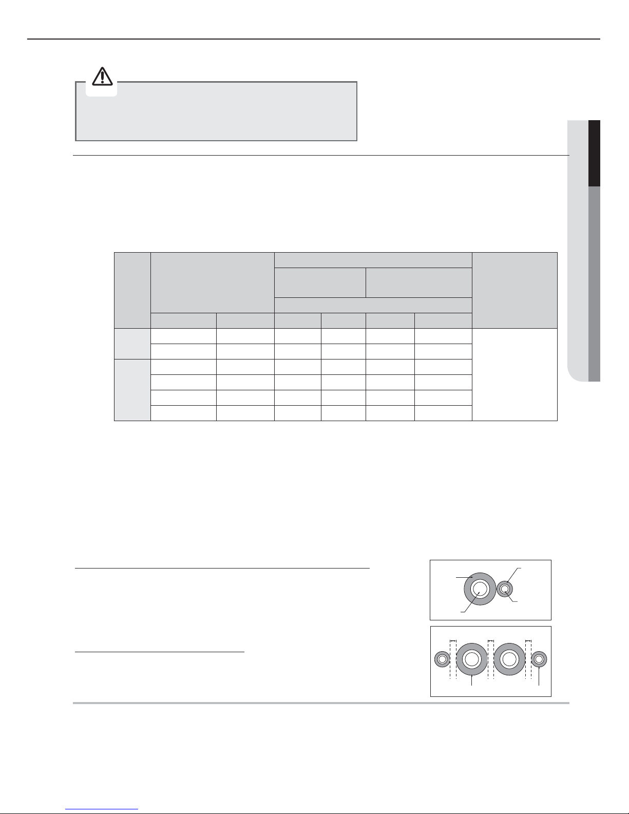
Select the insulator of the refrigerant pipe.
X Insulate the gas side and liquid side pipe referring to the thickness according to the pipe size.
X Indoor temperature of 30°C(86°F) and humidity of 85% is the standard condition.
If install in a high humidity condition,use one grade thicker insulator by
referring to the table below.
If installing in an unfavorable conditions, use thicker one.
X Insulator’s heat-resistance temperature should be more than 120°C(248°F).
X When installing insulation in places and conditions below, use the same insulation that is used for high
humidity conditions.
<Geological condition>
- High humidity places such as shoreline, hot spring, near lake or river, and ridge (when the part of the building
is covered by earth and sand.)
<Operation purpose condition>
- Restaurant ceiling, sauna, swimming pool etc.
<Building construction condition>
- The ceiling frequently exposed to moisture and cooling is not covered.
e.g. The pipe installed at a corridor of a dormitory and studio or near an exit that opens and closes frequently.
- The place where the pipe is installed is highly humid due to the lack of ventilation system.
Refrigerant pipe before EEV kit and MCU or without EEV kit and MCU
X You can contact the gas side and liquid side pipes but the
pipes should not be pressed.
X
When contacting the gas side and gas side pipe, use 1 grade
thicker insulator.
Refrigerant pipe after EEV kit
and MCU
X
Install the gas side and liquid side pipes, leave 10mm of space.
X
When contacting the gas side and liquid side pipe, use 1 grade
thicker insulator.
Gas pipe
Liquid pipe
Insulation
Insulation
Pipe
Pipe size
Insulation Type (Heating/Cooling)
Remarks
General
[30°C(86°F), 85%]
High humidity
[30°C(86°F), over 85%]
EPDM,NBR
mm inch mm inch mm inch
Liquid
pipe
6.35 ~ 9.52 1/4~3/8 9 3/8 9 3/8
Heating resisting
temperature over
120°C(248°F)
12.7 ~ 50.80 1/2~2 13 1/2 13 1/2
Gas
pipe
6.35 1/4 13 1/2 19 3/4
9.52 ~ 25.40 3/8~1 19 3/4 25 1
28.58 ~ 44.45 1 1/8~1 3/4 19 3/4 32 1 1/4
50.80 2 25 1 38 1 1/2
Gas pipe Liquid pipe
0.39"(10mm)
0.39"(10mm) 0.39"(10mm)
All refrigerant connection must be accessible, in order
to permit either unit maintenance or removing it
completely.
Caution
Page 27
26
A
Drain pipe and drain hose installation
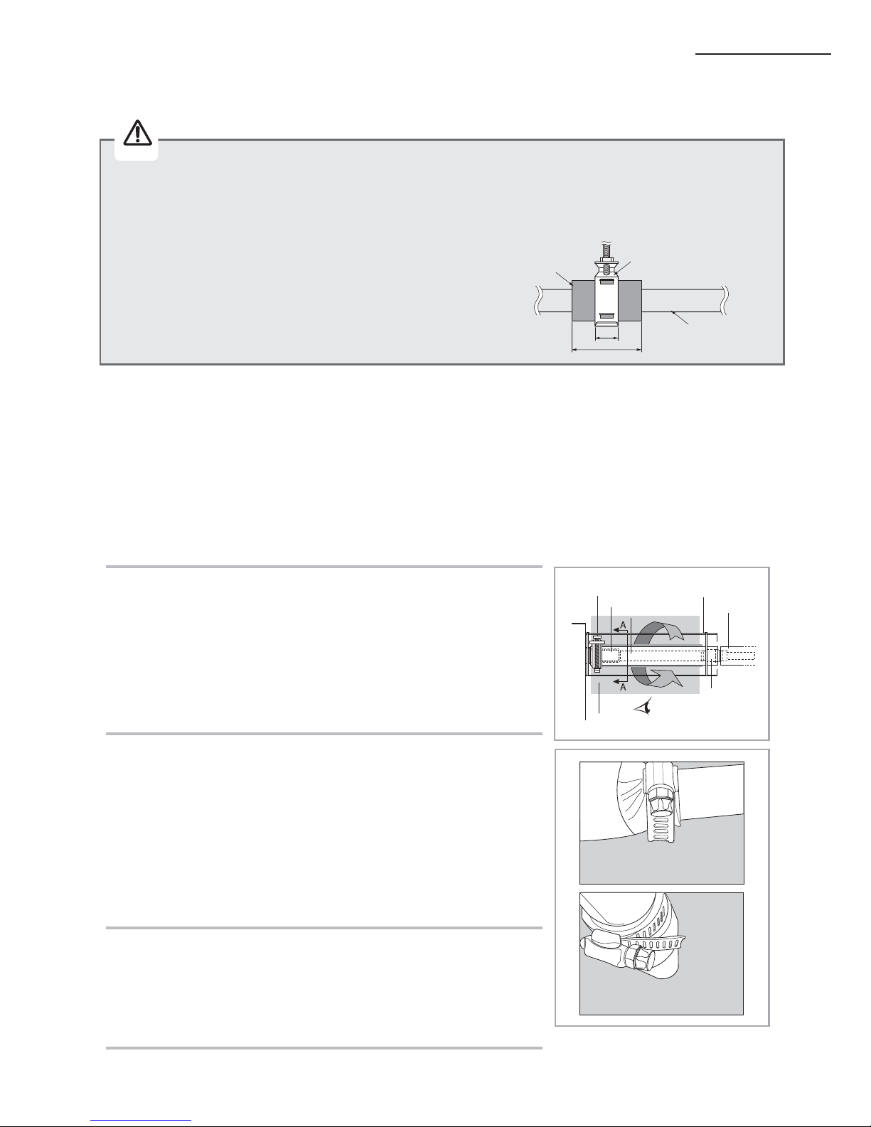
A-A’
Large sealing pad
Metal clamp
Drain socket
Drain hose
Cable tie
Drain piping
Indoor
unit
Tighten the clamp to the maximum.
1
Install the drain hose as short as possible.
note
X
In order to discharge condensation water, the drain hose should
keep tilted.
X
Secure the drain hose with the cable-tie not to be separated from
the unit.
X
The drain pump connection port is used when using a drain pump.
2
When there is no draining pump, insulate the drain hose and
then fix it as a picture.
note
XInsert the drain hose to bottom of the outfall of water basin.
X
Lock steel ring of the drain hose according to the figure.
X
Wind and wrap steel ring and drain hose fully with thermal
insulation sponge; fix both ends of external layer with ribbon for
thermal insulation.
X
After being installed, drain hose must be insulated fully by heat
insulating material.(To be provided at site.)
3
While using draining pump, insulate the drain hose with heat
insulating material according to the gure.
note
X
Check if the rubber ring is installed properly on the draining
pump.
X
Check if the drain cap blocks the outfall of drain pan properly.
Care must be taken when installing the drain hose for the indoor unit to ensure that any condensate
water is correctly drained outside. The drain hose can be installed to the right or left side of the base pan.
X Install the insulation not to get wider and use the adhesives on the connection part of it to
prevent moisture from entering.
X Wind the refrigerant pipe with insulation tape if it is exposed to outside sunlight.
X Install the refrigerant pipe respecting that the insulation does not
get thinner on the bent part or hanger of pipe.
X Add the additional insulation if the insulation plate
gets thinner.
Additional insulation
Hanger
Refrigerant pipe insulation
a×3
a
Caution
Performing leak test & insulation
Reducer
Page 28
27
A
ENGLISH
Drain pipe and drain hose installation
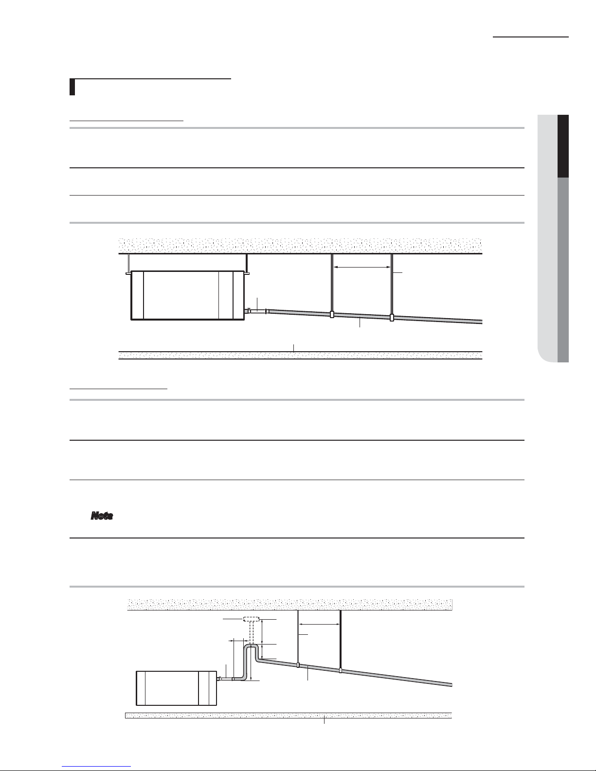
1
The drain pipe should be installed within 11.81inch(300mm) to 21.65inch(550mm) from the flexible hose
and then lift down 0.79inch(20mm) or more.
2
Install horizontal drainpipe with a slope of 1/100 or more and fix it by hanger space of
3.28~4.92ft(1.0~1.5m).
3
Install the air vent in the horizontal drainpipe to prevent water flow back to the indoor unit.
You may not need to install it if there were proper slope in the horizontal drainpipe.
Note
4
The flexible hose should not be installed upward position, it may cause water flow back to the
indoor unit.
With the drain pump
1
Install horizontal drainpipe with a slope of 1/100 or more and fix it by hanger space of
3.28~4.92ft(1~1.5m).
2
Install U-trap at the end of the drainpipe to prevent a nasty smell to reach the indoor unit.
3
Do not install the drainpipe to upward position. It may cause water flow back to the unit.
Without the drain pump
3.28~4.92ft
(1~1.5m)
Horizontal drainpipe
more than 1/100 slope
Ceiling
Hanger
Flexible hose
Flexible hose
Air vent
11.8inch(300mm) or less
Horizontal drainpipe
more than 1/100 slope
Within
11.81~21.65inch
(300~550mm)
3.28~4.92ft
(1~1.5m )
7.87inch
(200mm)
or more
Ceiling
Hanger
0.79inch
(20mm)or more
Drainpipe Connection
Page 29
28
A
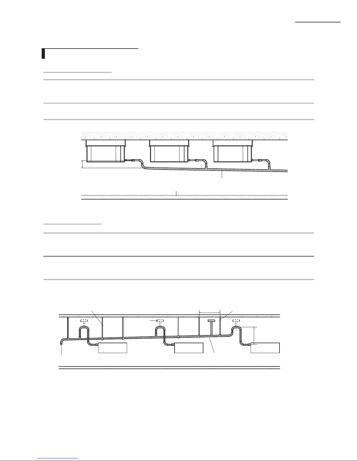
1
Install horizontal drainpipe with a slope of 1/100 or more and fix it by hanger space of
3.28~4.92ft(1~1.5m).
2
Install U-trap at the end of the drainpipe to prevent a nasty smell to reach the indoor unit.
Without the drain pump
1
Install main air vent at the front of the farthest indoor unit from the main drain when installed
indoor units are more than 3.
2
You may need to install individual air vent to prevent water flow back at the top of each indoor unit
drainpipe.
With the drain pump
Drain pipe and drain hose installation
3.94inch(100mm)
or more
Ceiling
Horizontal drainpipe
more than 1/100 slope
Main drainpipe
Hanger
Main air vent
Centralized horizontal drainpipe
(more than 1/100 slope)
21.65inch
(550mm) or less
3.28~4.92ft
(1~1.5m)
Individual
air vent
Centralized Drainage
Page 30
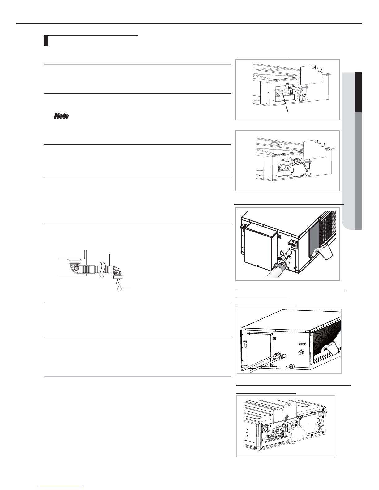
29
ENGLISH
Water supply intake
Prepare a little water about 2 liters.
Loosen screws and take out the side cover plate.
1
Confirm that the water flows out through the drain hose.
3
When the drain pump is installed, operate the unit as cooling mode
and check a drain pump pumping.
4
Pour water into the the indoor unit as shown in figure.
2
Drainage test should be done after installation has
been finished. To avoid water overflow from the
indoor unit because the drain tube is blocked.
Note
Reinstall the side cover plate.
7
Check drain water drops at the end of the drain pipe.
5
Make sure there is no water leak at the drainage.
6
Drainpipe
Drain water drops
AM77FNLD777
AM77FNMD777/AM77FNHD777
K The designs and shape are subject to change
according to the model.
Testing the drainage
AM77JNMD777/AM77JNHD777
AM77JNMP777
(Drain pump built-in)
AM77MNMD777/AM77MNHD777
(Drain pump built-in)
Page 31
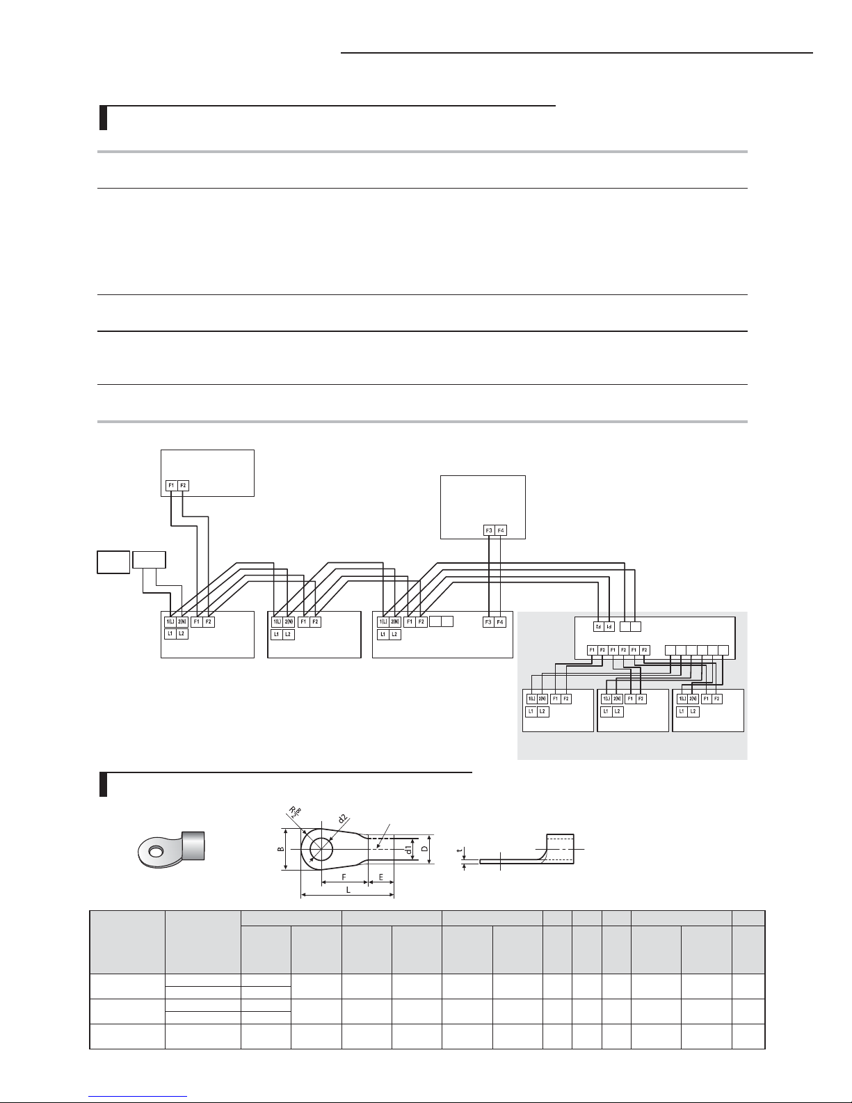
30
A
Wiring work
Silver solder
1
Before wiring work, you must turn off all power source.
2
Indoor unit power should be supplied through the breaker( ELCB or MCCB+ELB ) separated by the
outdoor power.
ELCB:Earth Leakage Circuit Breaker
MCCB:Molded Case Circuit Breaker
ELB:Earth Leakage Breaker
3
The power cable should be used only copper wires.
4
Connect the power cable{1(L), 2(N)} among the units within maximum length and communication
cable(F1, F2) each.
5
Connect F3, F4(for communication) when installing the wired remote control.
Norminal
dimensions for
cable (inch
2
)
Norminal
dimensions for
screw (inch)
BDd1EFLd2t
Standard
dimension
(inch)
Allowance
(inch)
Standard
dimension
(inch)
Allowance
(inch)
Standard
dimension
(inch)
Allowance
(inch)
Min. Min. Max.
Standard
dimension
(inch)
Allowance
(inch)
Min.
0.0023
0.16 0.26
±0.0079 0.13
+0.012
-0.0079
0.067 ±0.0079 0.16 0.24 0.63 0.17
+0.0079
0
0.028
0.16 0.31
0.0039
0.16 0.26
±0.0079 0.17
+0.012
-0.0079
0.091 ±0.0079 0.24 0.24 0.69 0.17
+0.0079
0
0.031
0.16 0.33
0.0062 0.16 0.37 ±0.0079 0.22
+0.012
-0.0079
0.134 ±0.0079 0.24 0.20 0.79 0.17
+0.0079
0
0.035
NL
NLNLNL
ELCB
MCCB+
ELB
V1 V2
Indoor Unit 1 Indoor Unit 2 Indoor Unit 3
Indoor Unit 4 Indoor Unit 5 Indoor Unit 6
Outdoor Unit
Wired Remote
Controller
EEV kit
K
Ceiling, wall-mounted indoor unit.
K
ELCB : Essential Installation
WARNING :
Power off before connecting any wires;
Indoor PBA will be damaged while V1,V2,F3,F4 short each
other.
208-230V~
or
Power and communication cable connection
Selecting compressed ring terminal
Page 32
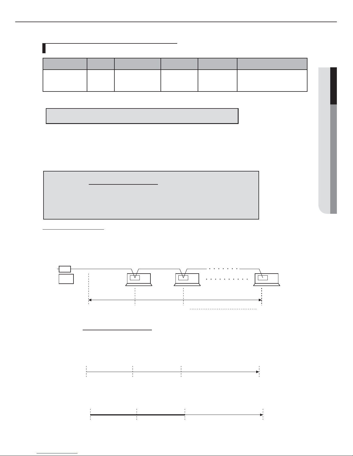
31
ENGLISH
Power supply MCCB ELB or ELCB Power cable Earth cable Communication cable
Max : 242V
Min : 198V
XA
X A, 30mA
0.1 sec
0.0039inch
2
(2.5mm2)
0.0039inch
2
(2.5mm2)
0.0012~0.0023inch
2
(0.75~1.5mm2)
X Decide the capacity of ELCB(or MCCB+ELB) by below formula.
The capacity of ELCB(or MCCB+ELB) X [A] = 1.25 X 1.1 X ∑ A i
7X
: The capacity of ELCB(or MCCB+ELB).
7∑Ai : Sum of Rating currents of each indoor unit.
7
Refer to each installation manual about the rating current of indoor unit.
X Decide the power cable specification and maximum length within 10% power drop among
indoor units.
7
coef: 1.55
7
Lk: Distance among each indoor unit[m(ft)], Ak: Power cable specification[mm2 (inch2)]
ik: Running current of each unit[A]
∑ (
Coef×35.6×Lk×ik
)<
10% of input voltage[V]
1000×A
k
n
k=1
Example of Installation
- Total power cable length L = 328ft(100m) , Running current of each units 1[A]
- Total 10 indoor units were installed
X
Apply following equation.
∑ (
Coef×35.6×L
k×ik
)<
10% of input
voltage[V]
1000×A
k
n
k=1
K Calculation
OInstalling with 1 sort wire.
OInstalling with 2 different sort wire.
10[A]
Indoor unit10
65.6ft(20m)32.8ft(10m)
0ft(0m)
9[A] 1[A]
328ft(100m)
Indoor unit2Indoor unit1
ELCB
220[V ]
-2.2[V ] -2.0[V ]
0.0039inch
2
(2.5mm2)
208.8[V](Within 198V~242V)
-(2.2+2.0+1.8+1.5+1.3+1.1+0.9+0.7+0.4+0.2) =-11.2[V ]
it's okay
0.0039inch2(2.5mm2) 0.0039inch2(2.5mm2)
220[V ]
-1.4[V ] -1.2[V ]
0.0039inch
2
(2.5mm2)
209.5[V](Within 198V~242V)
-(1.4+1.2+1.8+1.5+1.3+1.1+0.9+0.7+0.4+0.2) =-10.5[V ]
it's okay
0.0062inch2(4.0mm2) 0.0062inch2(4.0mm2)
Or
MCCB+
ELB
Specification of electronic wire
Page 33
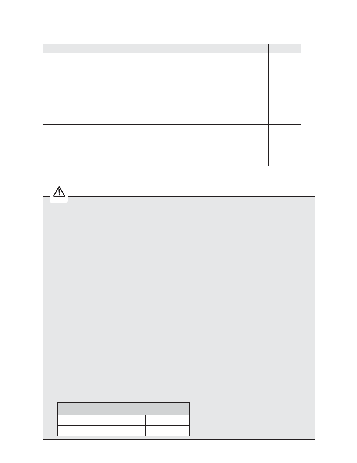
32
A
Wiring work(Cont.)
KRating current
Unit Model Rating current Unit Model Rating current Unit Model Rating current
AM7FNLD7
7
007
7
7
009
7
7
012
7
7
018
7
7
024
7
7
030
7
7
036
7
7
048
7
0.32A
0.40A
0.51A
0.94A
0.98A
0.80A
1.05A
1.40A
AM7FNMD77018
7
7
024
7
7
030
7
7
036
7
7
048
7
1.40A
1.50A
1.50A
1.60A
2.45A
AM7JNMD77007
7
7
009
7
7
012
7
7
015
7
7
018
7
0.24A
0.24A
0.26A
0.32A
0.40A
AM7FNHD7
7
036
7
7
048
7
1.47A
2.38A
AM7JNHD7
7
024
7
7
027
7
7
030
7
7
036
7
7
048
7
7
054
7
0.93A
0.95A
1.11A
1.29A
1.76A
2.10A
AM7MNMD77007
7
7
009
7
7
012
7
7
015
7
7
018
7
0.25A
0.25A
0.26A
0.30A
0.65A
AM7MNHD77024
7
7
027
7
7
030
7
7
036
7
7
048
7
0.81A
0.87A
0.92A
1.13A
1.84A
AM7JNMP7
7
006
7
7
018
7
7
028
7
7
042
7
0.24A
0.40A
0.95A
1.52A
X Select the power cable in accordance with relevant local and national regulations.
X Wire size must comply with local and national code.
X For the power cable, use the grade of H07RN-F or H05RN-F materials.
X You should connect the power cable into the power cable terminal and fasten it with a clamp.
X The unbalanced power must be maintained within 10% of supply rating among whole indoor units.
X
If the power is unbalanced greatly, it may shorten the life of the condenser. If the unbalanced power is
exceeded over 10% of supply rating, the indoor unit is protected, stopped and the error mode indicates.
X To protect the product from water and possible shock, you should keep the power cable and the
connection cord of the indoor and outdoor units in the iron pipe.
X Connect the power cable to the auxiliary circuit breaker.
An all pole disconnection from the power supply must be incorporated in the fixed
wiring[≥1/8"(3mm)].
X You must keep the cable in a protection tube.
X Keep distances of 2"(50mm) or more between power cable and communication cable.
X Maximum length of power cables are decided within 10% of power drop. If it exceeds, you must
consider another power supplying method.
X The circuit breaker(ELCB or MCCB+ELB) should be considered more capacity if many indoor units
are connected from one breaker.
X Use round pressure terminal for connections to the power terminal block.
X For wiring, use the designated power cable and connect it firmly, then secure to prevent outside
pressure being exerted on the terminal board.
X Use an appropriate screwdriver for tightening the terminal screws. A screwdriver with a small head
will strip the head and make proper tightening impossible.
X Over-tightening the terminal screws may break them.
X See the table below for tightening torque for the terminal screws.
Tightening torque
M3.5 0.8~1.2 N·m 0.59~0.89 lbf·ft
M4 1.2~1.8 N·m 0.89~1.33 lbf·ft
Caution
Page 34
33
A
ENGLISH
Setting an indoor unit address and
installation option
Set the indoor unit address and installation option with remote controller option.
Set the each option separately since you cannot set the ADDRESS setting and indoor unit installation setting
option at the same time. You need to set twice when setting indoor unit address and installation option.
Step 1. Entering mode to set option
1. Remove batteries from the remote controller.
2. Insert batteries and enter the option setting mode while pressing High Temp button and Low Temp button.
3. Check if you have entered the option setting status.
Step 2. The procedure of option setting
After entering the option setting status, select the option as listed below.
Option setting is available from SEG1 to SEG 24
X SEG1, SEG7, SEG13, SEG19 are not set as page option.
X Set the SEG2~SEG6, SEG8~SEG12 as ON status and SEG14~18, SEG20~24 as OFF status.
SEG1 SEG2 SEG3 SEG4 SEG5 SEG6 SEG7 SEG8 SEG9 SEG10 SEG11 SEG12
0XXXXX1XXXXX
SEG13 SEG14 SEG15 SEG16 SEG17 SEG18 SEG19 SEG20 SEG21 SEG22 SEG23 SEG24
2XXXXX3XXXXX
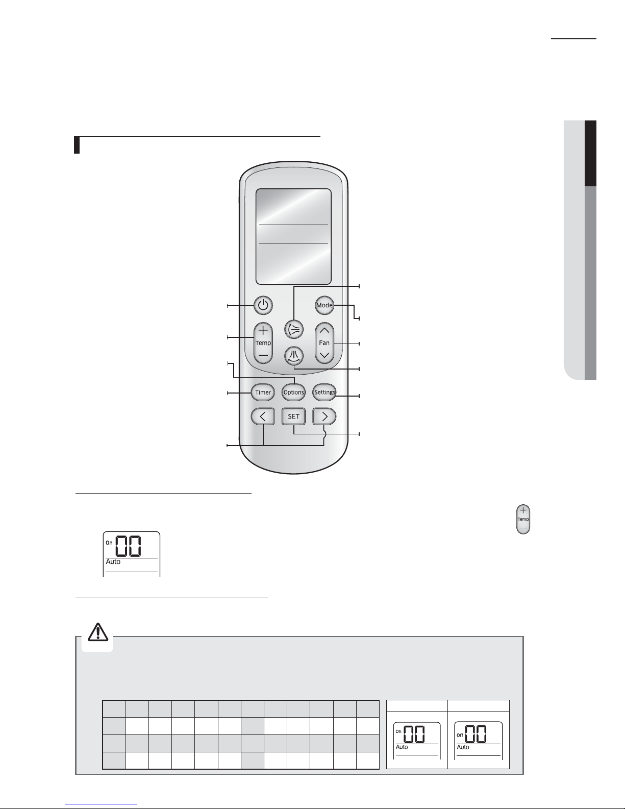
On(SEG1~12) O(SEG13~24)
Mode
Selects operation mode.
Air ow direction (Left and right)
Adjusts the air ow direction left and right.
Fan speed
Adjusts the fan speed.
Air ow direction (Up and down)
Adusts the air ow direction up and down
(Not applicable to Duct type models).
SET
Selects or cancels an option.
Settings
Selects settings.
Power
Turns the air conditioner on or o.
Temperature
Adjusts the temperature.
Options
Selects options during operation.
Direction
Moves to select and set an option.
Timer
Sets timer option.
The procedure of option setting
Caution
Page 35
34
A
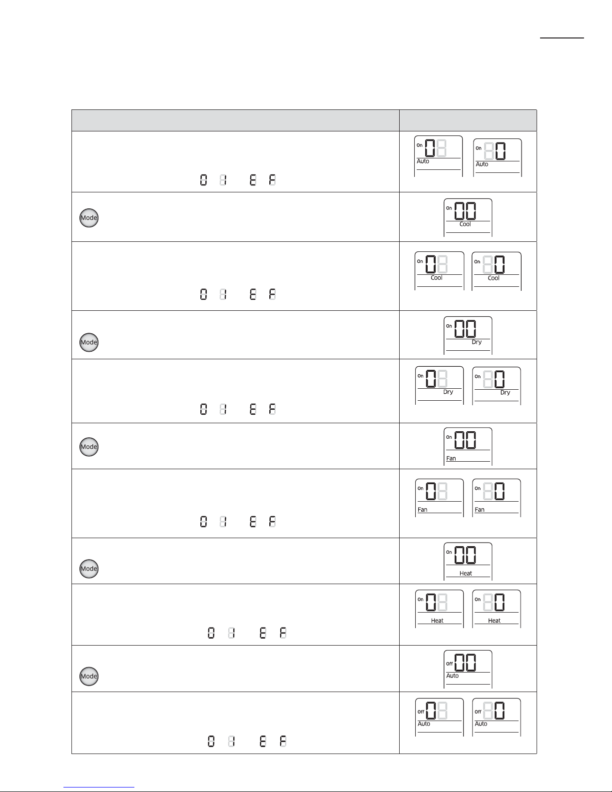
Option setting Status
1. Setting SEG2, SEG3 option
Press Low Fan button(∨) to enter SEG2 value.
Press High Fan button(
∧
) to enter SEG3 value.
Each time you press the button,
⋯ will be selected in rotation.
2. Setting Cool mode
Press Mode button to be changed to Cool mode in the ON status.
3. Setting SEG4, SEG5 option
Press Low Fan button(
∨
) to enter SEG4 value.
Press High Fan button(
∧
) to enter SEG5 value.
Each time you press the button,
⋯ will be selected in rotation.
4. Setting Dry mode
Press Mode button to be changed to DRY mode in the ON status.
5. Setting SEG6, SEG8 option
Press Low Fan button(
∨
) to enter SEG6 value.
Press High Fan button(
∧
) to enter SEG8 value.
Each time you press the button,
⋯ will be selected in rotation.
6. Setting Fan mode
Press Mode button to be changed to FAN mode in the ON status.
7. Setting SEG9, SEG10 option
Press Low Fan button(
∨
) to enter SEG9 value.
Press High Fan button(
∧
) to enter SEG10 value.
Each time you press the button,
⋯ will be selected in rotation.
8. Setting Heat mode
Press Mode button to be changed to HEAT mode in the ON status.
9. Setting SEG11, SEG12 option
Press Low Fan button(
∨
) to enter SEG11 value.
Press High Fan button(
∧
) to enter SEG12 value.
Each time you press the button,
⋯ will be selected in rotation.
10. Setting Auto mode
Press Mode button to be changed to AUTO mode in the OFF status.
11. Setting SEG14, SEG15 option
Press Low Fan button(
∨
) to enter SEG14 value.
Press High Fan button(
∧
) to enter SEG15 value.
Each time you press the button,
⋯ will be selected in rotation.
SEG2 SEG3
SEG4
SEG6
SEG9
SEG11
SEG14
SEG5
SEG8
SEG10
SEG12
SEG15
Setting an indoor unit address and
installation option (Cont.)
Page 36
35
ENGLISH
SEG16
SEG18
SEG21
SEG23
SEG17
SEG20
SEG22
SEG24
Step 4. Input option
Press operation button
with the direction of remote control for set.
For the correct option setting, you must input the option twice.
Step 5. Check operation
1. Reset the indoor unit by pressing the RESET button of indoor unit or outdoor unit.
2. Take the batteries out of the remote controller and insert them again and then press the operation button.
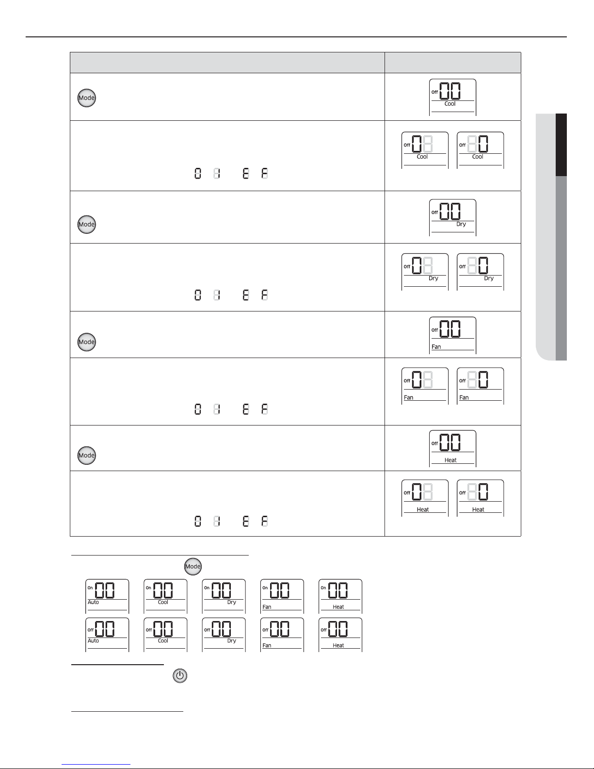
Option setting Status
12. Setting Cool mode
Press Mode button to be change to Cool mode in the OFF status.
13. Setting SEG16, SEG17 option
Press Low Fan button(
∨
) to enter SEG16 value.
Press High Fan button(
∧
) to enter SEG17 value.
Each time you press the button,
⋯ will be selected in rotation.
14. Setting Dry mode
Press Mode button to be change to Dry mode in the OFF status.
15. Setting SEG18, SEG20 option
Press Low Fan button(
∨
) to enter SEG18 value.
Press High Fan button(
∧
) to enter SEG20 value.
Each time you press the button,
⋯ will be selected in rotation.
16. Setting Fan mode
Press Mode button to be change to Fan mode in the OFF status.
17. Setting SEG21, SEG22 option
Press Low Fan button(
∨
) to enter SEG21 value.
Press High Fan button(
∧
) to enter SEG22 value.
Each time you press the button,
⋯ will be selected in rotation.
18. Setting Heat mode
Press Mode button to be change to HEAT mode in the OFF status.
19. Setting SEG23, SEG24 mode
Press Low Fan button(
∨
) to enter SEG23 value.
Press High Fan button(
∧
) to enter SEG24 value.
Each time you press the button,
⋯ will be selected in rotation.
Step 3. Check the option you have set
After setting option, press
button to check whether the option code you input is correct or not.
¤
¤
¤
¤
¤
¤
¤
¤
¤
Page 37
36
A
Setting an indoor unit address and
installation option (Cont.)
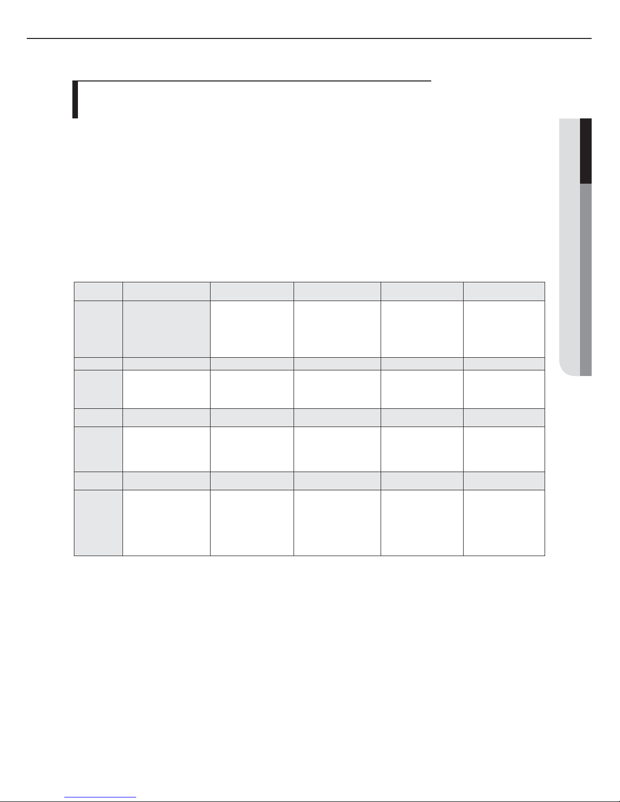
1.
Check whether power is supplied or not.
- When the indoor unit is not plugged in, there should be additional power supply in the indoor unit.
2.
The panel(display) should be connected to an indoor unit to receive option.
3.
Before installing the indoor unit, assign an address to the indoor unit according to the air conditioning system plan.
4. Assign an indoor unit address by wireless remote controller.
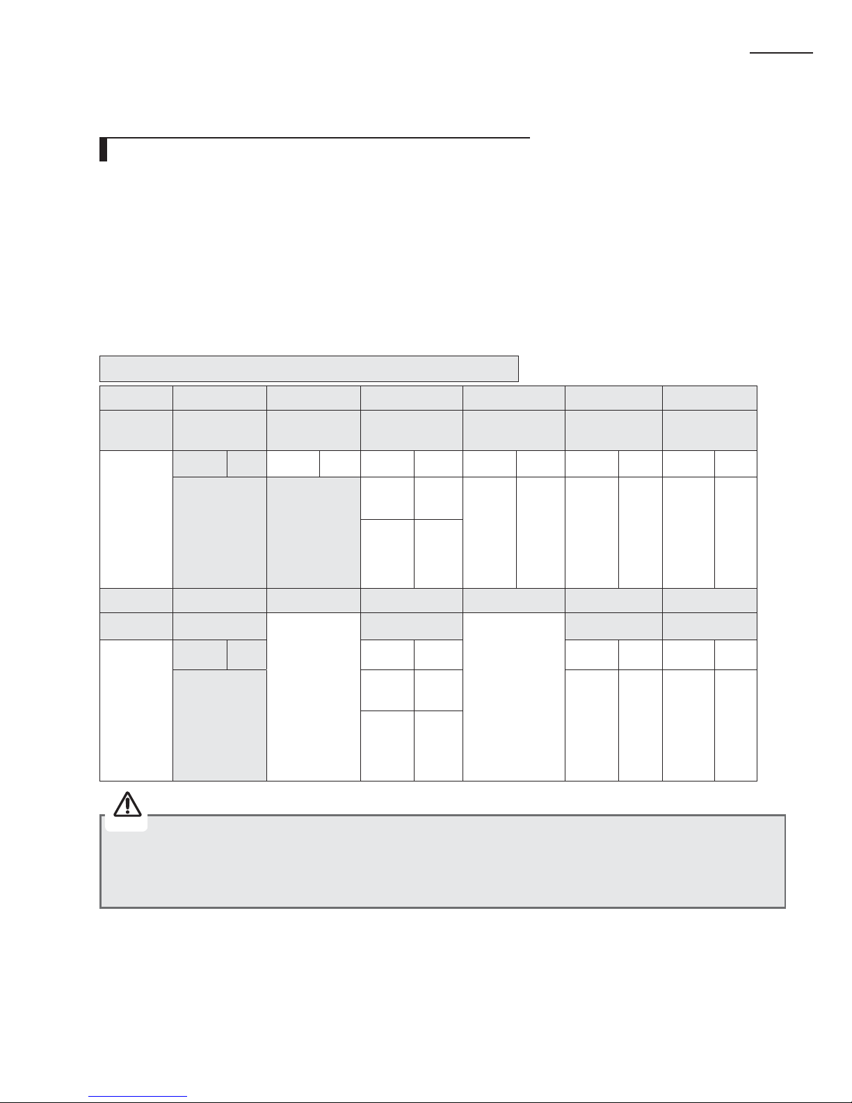
- The initial setting status of indoor unit ADDRESS(MAIN/RMC) is “0A0000-100000-200000-300000”.
Option No. : 0AXXXX-1XXXXX-2XXXXX-3XXXXX
Option
SEG1 SEG2 SEG3 SEG4 SEG5 SEG6
Explanation
PAGE Mode Setting Main address
100-digit of indoor
unit address
10-digit of indoor
unit
The unit digit of
an indoor unit
Indication
and Details
Indication Details Indication Details Indication Details Indication Details Indication Details Indication Details
0A
0
No Main
address
0~9 100-digit 0~9 10-digit 0~9
A unit
digit
1
Main
address
setting
mode
Option
SEG7 SEG8 SEG9 SEG10 SEG11 SEG12
Explanation
PAG E
__
Setting RMC address
__
Group channel(*16) Group address
Indication
and Details
Indication Details Indication Details Indication Details Indication Details
1
0
No RMC
address
RMC1 0~F RMC2 0~F
1
RMC
address
setting
mode
X When “A”~”F” is entered to SEG5~6, the indoor unit MAIN ADDRESS is not changed.
X If you set the SEG 3 as 0, the indoor unit will maintain the previous MAIN ADDRESS even if you input the option value of SEG5~6.
X If you set the SEG 9 as 0, the indoor unit will maintain previous RMC ADDRESS even if you input the option value of SEG11~12.
X You cannot set SEG11 and SEG12 as F value at the same time.
Setting an indoor unit address (MAIN/RMC)
Caution
Page 38
37
ENGLISH
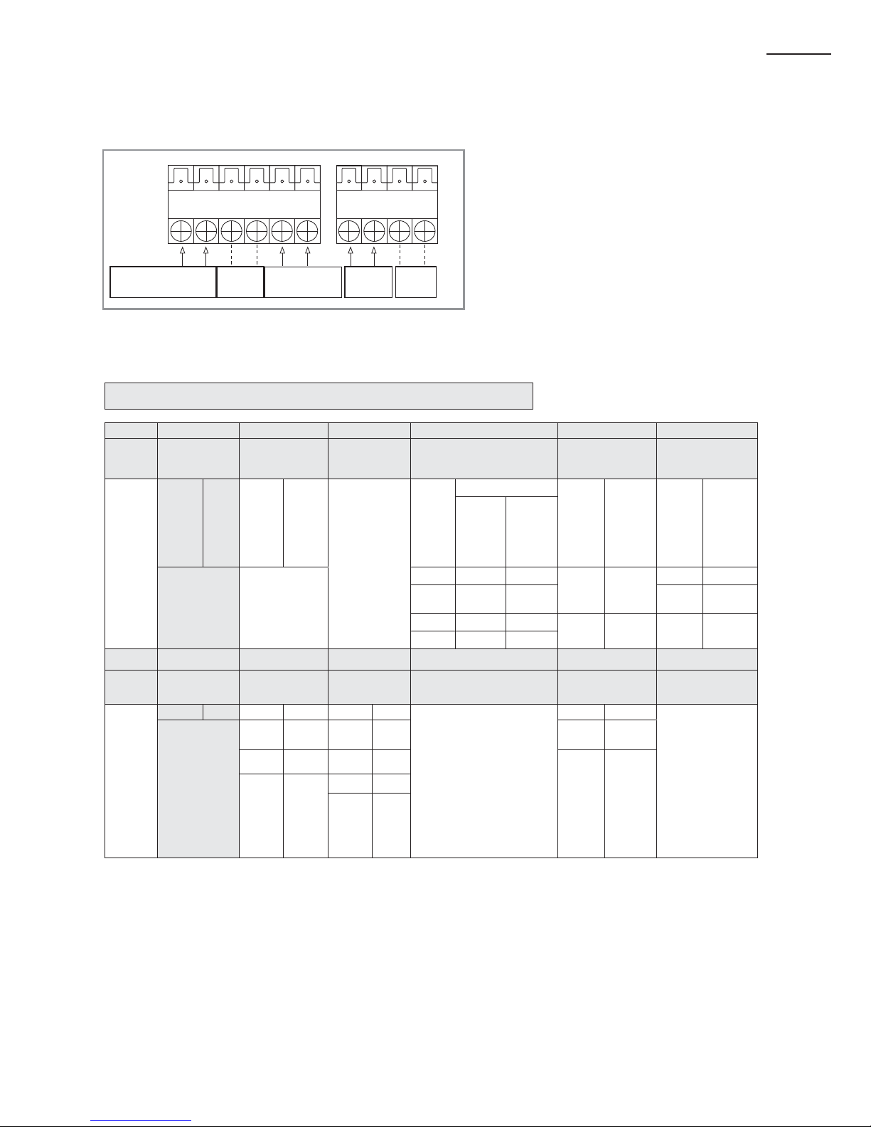
1.
Check whether power is supplied or not.
- When the indoor unit is not plugged in, there should be additional power supply in the indoor unit.
2.
The panel(display) should be connected to an indoor unit to receive option.
3.
Set the installation option according to the installation condition of an air conditioner.
- The default setting of an indoor unit installation option is “020010-100000- 200000-300000”.
- Individual control of a remote controller(SEG20) is the function that controls an indoor unit
individually when there is more than one indoor unit.
4.
Set the indoor unit option by wireless remote controller.
SEG1 SEG2 SEG3 SEG4 SEG5 SEG6
02 --
External room
temperature sensor
/ Minimizing fan
operation when
thermostat is o
Central control
FAN RPM
compensation
SEG7 SEG8 SEG9 SEG10 SEG11 SEG12
1 Drain pump Hot water heater --
EEV Step when
heating stops
--
SEG13 SEG14 SEG15 SEG16 SEG17 SEG18
2 External control
External control
output / External
heater On or O
signal
- Buzzer
Number of hours
using lter
SEG19 SEG20 SEG21 SEG22 SEG23 SEG24
3
Individual control of
a remote controller
Heating setting
compensation
/ Removing
condensated water
in heating mode
EEV Step of stopped
unit during oil
return/defrost mode
---
X 1 WAY/2WAY/4WAY,DUCT MODEL : Number of hours using filter(SEG18) will be set to ‘1000hour’ even
if the SEG18 is set to exept for 2 or 6.
X
When setting the option other than above SEG values, the option will be set as “0”.
X
SEG5 central control option is basically set as 1 (Use), so you don’t need to set the central control
option additionally.
However, if the central control is not connected but it doesn’t indicate an error message, you need to
set the central control option as 0 (Disuse) to exclude the indoor unit from the central control.
Q
02 series installation option
Setting an indoor unit installation option
(suitable for the condition of each installation location)
Page 39
38
A
Setting an indoor unit address and
installation option (Cont.)
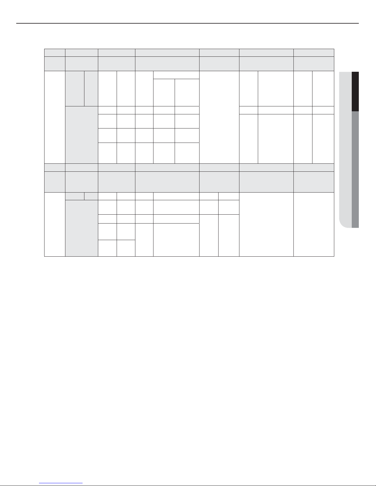
Option No. : 02XXXX-1XXXXX-2XXXXX-3XXXXX
Q
02 series installation option(Detailed)
F4
F3
F1 F2
V2
V1
1(L) 2(N)
2
1
HOT
COIL
AC
POWER
OUTDOOR
COMMUNICATION
Wire Remote
Controller
DC 12V
* The output of hot coil terminal is AC 220 V / 230 V
(The same as Indoor Unit’s input Power)
COM1 COM2
(+) L N (-)
X The external output of SEG15 is generated by MIM-B14 connection. (Refer to the manual of MIM-B14.)
Option SEG1 SEG2 SEG3 SEG4 SEG5 SEG6
Explanation PAGE MODE -
Use of external room temperature
sensor / Minimizing fan operation
when thermostat is o
Use of central control FAN RPM compensation
Indication
and Details
Indication Details I ndication Details
-
Indication
Details
Indication Details Indication Details
Use of
External
room
temperature
sensor
Minimizing
fan operation
when
thermostat
is o
02
0
Disuse
Disuse
0 Disuse
0 Disuse
1 Use Disuse 1
RPM
compensation
2
Disuse Use
(*1)
1Use2
High ceiling
KIT
3Use
Use
(*1)
Option SEG7 SEG8 SEG9 SEG10 SEG11 SEG12
Explanation PAGE Use of drain pump
Use of hot water
heater
EEV Step when heating
stops
Indication
and Details
Indication Details I ndication Details Indication Details Indication Details
1
0 Disuse 0 Disuse 0
Default
value
1Use1
Use
(*2)
1
Noise
decreasing
setting
2
When an
indoor unit
stops, drain
pump will
operate for
3min
2--
3
Use
(*2)
X
The output of hot water heater in SEG9 is generated from the hot coil part of the terminal board in duct models.
Page 40
39
ENGLISH
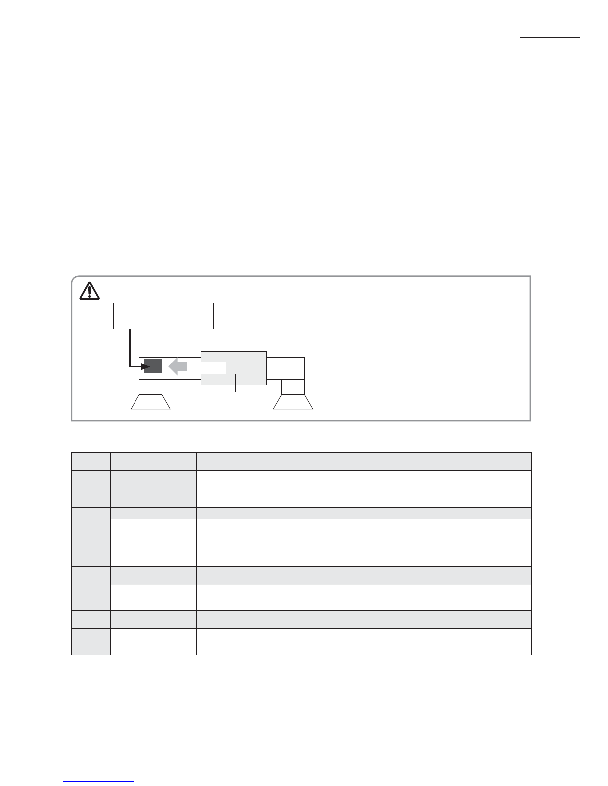
Option SEG13 SEG14 SEG15 SEG16 SEG17 SEG18
Explanation PAGE
Use of external
control
Setting the output of external control
/ External heater On/O signal
- Buzzer control Hours of lter usage
Indication
and Details
Indication Details Indication Details Indication
Details
-
Indication Details Indication Details
Setting the
output of
external
control
External
heater On/O
signal
2
0 Disuse 0 Thermo on - 0 Use buzzer 2 1000 Hour
1
ON/OFF
control
1
Operation
on
-
1 Disuse buzzer
6 2000 Hour
2
OFF
control
2 - Use
(*3)
3
Window
ON/OFF
control
3 - Use
(*3)
Option SEG19 SEG20 SEG21 SEG22 SEG23 SEG24
Explanation PAGE
Individual control of
a remote controller
Heating setting compensation
EEV Step of stopped
unit during oil return/
defrost mode
--
Indication
and Details
Indication Details Indication Details Indication Details Indication Details
--
3
0 or 1 channel 1 0 Default
(*4)
0
Default
value
2 channel 2 1
2 °C (3.6 °F)
1
Oil return
or Noise
decreasing
in defrost
mode
3 channel 3
2 5 °C (9 °F)
4 channel 4
Page 41
40
A
Setting an indoor unit address and
installation option (Cont.)
SEG1 SEG2 SEG3 SEG4 SEG5 SEG6
05
Use of Auto Change Over
for HR only in Auto mode
(When setting SEG3)
Standard heating temp.
Oset
(When setting SEG3)
Standard cooling temp.
Oset
(When setting SEG3)
Standard for mode change
Heating → Cooling
SEG7 SEG8 SEG9 SEG10 SEG11 SEG12
1
(When setting SEG3)
Standard for mode change
Cooling → Heating
(When setting SEG3)
Time required for mode
change
Compensation option for
Long pipe or height
dierence between
indoor units
--
SEG13 SEG14 SEG15 SEG16 SEG17 SEG18
2- - - -
Control variables when using
hot water / external heater
SEG19 SEG20 SEG21 SEG22 SEG23 SEG24
3- - - - -
Q
05 series installation option
*
Advanced function: Controlling cooling/heating current or power saving with motion detect.
(*1) Minimizing fan operation when thermostat is o
- Fan operates for 20 seconds at an interval of 5 minutes in heat mode.
(*2) 1: Fan is turned on continually when the hot water heater is turned on,
3: Fan is turned o when the hot water heater is turned on with cooling only indoor unit
Cooling only indoor unit: To use this option,install the Mode Select switch(MCM-C200) on the outdoor unit and x it as cool mode.
(*3) When the following 2 or 3 is used as external heater On/O signal, the signal for monitoring external contact control will not be output.
2: Fan is turned on continually when the external heater is turned on,
3: Fan is turned o when the external heater is turned on with cooling only indoor unit
Cooling only indoor unit: To use this option,install the Mode Select switch(MCM-C200) on the outdoor unit and x it as cool mode.
g If Fan is set to o for cooling only indoor unit by setting the SEG9=3 or SEG15=3, you need to use an external sensor or wired remote
controller sensor to detect indoor temperature exactly.
(*4) Default setting value
- 4Way Cassette, Mini 4Way Cassette: 9 °F(5 °C)
- Other indoor units: 3.6 °F(2 °C )
Air Flow
Suction side Discharge side
Electronic heater should
not be installed.
t Do not install the electronic heater in the ow channel of the indoor unit fan.
Duct Indoor unit
Caution
Page 42
41
ENGLISH
Option No. : 05XXXX-1XXXXX-2XXXXX-3XXXXX
Option SEG1 SEG2 SEG3 SEG4 SEG5 SEG6
Explanation
PAGE MODE
Use of Auto Change
Over for HR only in
Auto mode
(When setting SEG3)
Standard heating
temp. Oset
(When setting SEG3)
Standard cooling temp.
Oset
(When setting SEG3)
Standard for mode
change
Heating
→
Cooling
Indication
and Details
Indication Details Indication Details Indication Details Indication Details Indication Details Indication Details
05
0
Follow
product
option
0 0°F(0°C) 0 0°F(0°C) 0 1.8°F(1°C)
1
Use Auto
Change
Over for
HR only
1 0.9°F(0.5°C) 1 0.9°F(0.5°C) 1 2.7°F(1.5°C)
2 1.8°F(1°C) 2 1.8°F(1°C) 2 3.6°F(2°C)
3 2.7°F(1.5°C) 3 2.7°F(1.5°C) 3 4.5°F(2.5°C)
4 3.6°F(2°C) 4 3.6°F(2°C) 4 5.4°F(3°C)
5 4.5°F(2.5°C) 5 4.5°F(2.5°C) 5 6.3°F(3.5°C)
6 5.4°F(3°C) 6 5.4°F(3°C) 6 7.2°F(4°C)
7 6.3°F(3.5°C) 7 6.3°F(3.5°C) 7 8.1°F(4.5°C)
Option SEG7 SEG8 SEG9 SEG10 SEG11 SEG12
Explanation
PAG E
(When setting SEG3)
Standard for mode
changing Cooling
→
Heating mode
(When setting SEG3)
Time required for
mode change
Compensation option
for Long pipe or height
diference between
indoor units
Indication
and Details
Indication Details Indication Details Indication Details Indication Details
1
0 1.8°F(1°C) 0 5 min. 0
Use default
value
1 2.7°F(1.5°C) 1 7 min.
1
1) Height
difference
1)
is
more than 30m
( 98.4ft) or
2) Distance
2)
is longer than
110m(360.9ft)
2 3.6°F(2°C) 2 9 min.
3 4.5°F(2.5°C) 3 11 min.
4 5.4°F(3°C) 4 13 min.
2
1) Height
difference
1)
is
15~30m( 49.2ft
~ 98.4ft )or
2) Distance
2)
is
50~110m
(164.04ft~
360.9ft)
5 6.3°F(3.5°C) 5 15 min.
6 7.2°F(4°C) 6 20 min.
7 8.1°F(4.5°C) 7 30 min.
Q
05 series installation option(Detailed)
Page 43
42
A
(*1) Height dierence : The dierence of the height between the corresponding indoor uint and the indoor unit installed at the lowest place.
For example, When the indoor unit is installed 131.2ft(40m) higher than the indoor unit installed at the lowest place, select
the option "1".
(*2)
Distance : The dierence between the pipe length of the indoor unit istalled at farthest place from an outdoor unit and the pipe length of the
corresponding indoor unit from an outdoor unit.
For example, when the farthest pipe length is 100m(328 ft) and the corresponding indoor unit is 40m(131.23ft) away from an
outdoor unit, select the option "2".
[328-131.2=196.8ft(100 - 40 = 60m)]
(*3) Heater operation when the SEG9 of 02 series installation option is set to using hot water heater or when SEG15 is set to using external heater
e.g. 1) Setting 02 series SEG9 =”1” / Setting 05 series SEG18 = “0”: Hot water heater is turned on at the same time as the heating
thermostat is on, and turned o when the heating thermostat is o.
e.g. 2) Setting 02 series SEG15 =”2” / Setting 05 series SEG18 =”A”:
Room temp. ≤ set temp. + f(heating compensation temp.)
- External heater is turned on when the temperature is maintained as 8.1 °F(4.5 °C) for 10 minutes.
Room temp. > set temp. + f(heating compensation temp.)
- External heater is turned o when the temperature is maintained as 8.1 °F(4.5 °C) + 1.8 °F(1 °C) (1 °C is the Hysteresis for On/O
selection.)
Option SEG13 SEG14 SEG15 SEG16 SEG17
SEG18
(*3)
Explanation Control variables when using hot water / external heater
Indication
and Details
2
Indication
Details
Set temp. for heater On/O
Delay time for heater On
0 At the same time as thermo on No delay
1
At the same time as thermo on
10 minutes
2 At the same time as thermo on 20 minutes
3 2.7 °F(1.5 °C) No delay
4 2.7 °F(1.5 °C) 10 minutes
5 2.7 °F(1.5 °C) 20 minutes
6 5.4 °F(3.0 °C) No delay
7 5.4 °F(3.0 °C) 10 minutes
8 5.4 °F(3.0 °C) 20 minutes
9 8.1 °F(4.5 °C) No delay
A 8.1 °F(4.5 °C) 10 minutes
B 8.1 °F(4.5 °C) 20 minutes
C 10.8 °F(6.0 °C) No delay
D 10.8 °F(6.0 °C) 10 minutes
E 10.8 °F(6.0 °C) 20 minutes
Setting an indoor unit address and
installation option (Cont.)
Page 44
43
ENGLISH
Option SEG1 SEG2 SEG3 SEG4 SEG5 SEG6
Explanation PAGE MODE
The option mode
you want to change
The tens’ digit of an
option SEG you will
change
The unit digit of an
option SEG you will
change
Changed value
Indication
and Details
Indication Details Indication Details Indication Details Indication Details Indication Details Indication Details
0D
Option
mode
1~6
Tens’ digit
of SEG
0~9
Unit digit
of SEG
0~9
The
changed
value
0~F
You can change each digit of set option.
Option SEG1 SEG2 SEG3 SEG4 SEG5 SEG6
Explanation PAGE MODE
The option mode you
want to change
The tens’ digit of an
option SEG you will
change
The unit digit of an
option SEG you will
change
Changed value
Indication 0 D 2 1 7 1
t 8IFODIBOHJOHBEJHJUPGBOJOEPPSVOJUBEESFTTTFUUJOHPQUJPOTFUUIF4&(BTA"
t 8IFODIBOHJOHBEJHJUPGJOEPPSVOJUJOTUBMMBUJPOPQUJPOTFUUIF4&(BTA
Ex) When setting the ‘buzzer control’ into disuse status.
Note
SEG 3, 4, 5, 6, 8, 9 additional information
When the SEG 3 is set as "1" and follow Auto Change Over for HR only operation, it will operate as follows.
Cooling/Heating mode can be changed when Thermo O status is maintained during the time with SEG9.
A : Set with SEG4
B : Set with SEG5
C : Set with SEG6
D : Set with SEG8
Cooling Thermo O
Heating Thermo O
Cooling Thermo On
Heating Thermo On
BC
D
Ts
A
c
a
Temp.
d
b
Standard temp.
for Heating
Standard temp.
for Cooling
Standard temp. for
Heating
→
Cooling
Standard temp.
for Cooling
→
Heating
Set temp.
for Auto mode
X If you are using heat pump model, mixed operation mode (two or more indoor units operating in different operation
mode simultaneously) is not available when the indoor units are connected to same outdoor unit. If you set the master
indoor unit with a remote controller, outdoor unit will operate in the mode which was set in the master indoor unit.
Changing a particular option
Caution
Page 45
44
To complete the installation, perform the following checks and tests to ensure that the air
conditioner operates correctly.
Check the following:
X Strength of the installation site
X Tightness of pipe connection to detect gas leak
X Electric wiring connection
X Heat-resistant insulation of the pipe
X Drainage
X Grounding conductor connection
X Correct operation (follow the steps below)
Final check and trial operation
1. Use of “Temperature control of discharge air” or target temperature of discharge air in cooling/heating
can be set with the service mode of a wired remote controller. (Refer to the installation manual of a
wired remote controller.)
2. When using temperature control of discharge air, thermo on/o of Indoor unit is decided by set room
temperature and room temperature, and the temperature of discharge air is adjusted to meet the
target temperature of discharge air in thermostat On section.
3. When using temperature control of discharge air, the temperature of discharge air cannot always be
adjusted to the target temperature due to external conditions or protective control of the outdoor
unit.
❋ Temperature control of discharge air can be set with DMS as well.
Setting temperature control of discharge air
Page 46
45
A
ENGLISH
After finishing the installation of the air conditioner, you should explain the following to the user.
Refer to appropriate pages in the user & installation manual.
1
How to start and stop the air conditioner
2
How to select the modes and functions
3
How to adjust the temperature and fan speed
4
How to adjust the airflow direction
5
How to set the timers
6
How to clean and replace the filters
Note When you complete the installation successfully, hand over the user & installation
manual to the user for storage in a handy and safe place.
Providing information for user
X
If you turn off the air conditioner when the LED is flickering, the LED is also turned off.
X
If you re-operate the air conditioner, it operates normally at first, then detect an error again.
X
When E108 error occurs, change the address and reset the system.Ex.) When address of the indoor
unit #1 and #2 are set as 5, address of the indoor unit #1 will become 5 and indoor unit #2 will
display E108, A002.
Troubleshooting
X If an error occurs during the operation, an LED flickers and the operation is stopped except the LED.
X If you re-operate the air conditioner, it operates normally at first, then detect an error again.
LED Display on the receiver & display unit
Detection of errors
LED Display
Page 47
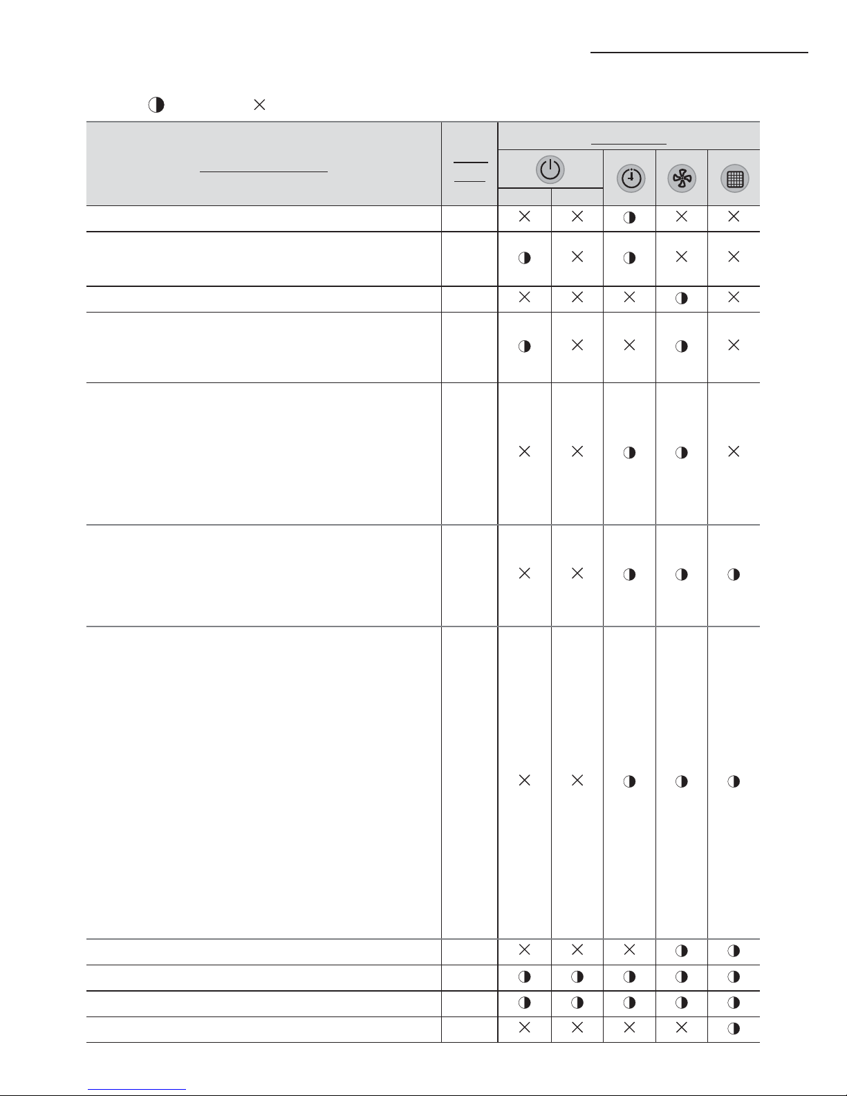
46
A
Troubleshooting (Contiued)
Abnormal condition
Error
code
LED Display
Blue Red
Error on indoor temperature sensor (Short or Open)
E121
1. Error on Eva-in sensor (Short or Open)
2. Error on Eva-out sensor (Short or Open)
3. Discharge sensor error (Short or Open)
E122
E123
E126
Indoor fan error
E154
1. Error on outdoor temperature sensor (Short or Open)
2. Error on cond sensor
3. Error on discharge sensor
Other outdoor unit sensor error that is not on the above list
E221
E237
E251
1. When there is no communication between the indooroutdoor
units for 2 minutes
2. Communication error received from the outdoor unit
3. 3 miniute tracking error on outdoor unit
4. Communication error after tracking due to unmatching number
of installed units
5. Error due to repeated communication address
6. Communication address not confirmed
Other outdoor unit communication error that is not on the above list
E101
E102
E202
E201
E108
E109
Self diagnosis error display
1. Error due to opened EEV (2nd detection)
2. Error due to closed EEV (2nd detection)
3. Eva in sensor is detached
4. Eva out sensor is detached
5. Thermal fuse error (Open)
E151
E152
E128
E129
E198
1. COND mid sensor is detached
2. Refrigerant leakage (2nd detection)
3. Abnomally high temperature on Cond (2nd detection)
4. Low pressure s/w (2nd detection)
5. Abnomally high temperature on discharged air on outdoor unit
(2nd detection)
6.
Indoor operation stop due to unconfirmed error on outdoor unit
7. Error due to reverse phase detection
8. Comp stop due to freeze detection (6th detection)
9. High pressure sensor is detached
10. Low pressure sensor is detached
11. Outdoor unit copression ration error
12. Outdoor sump down_1 prevetion control
13. Compressor down due to low pressure sensor prevention
control_1
14. Simultaneous opening of cooling/heating MCU SOL valve
(1st detection)
15. Simultaneous opening of cooling/heating MCU SOL valve
(2nd detection)
Other outdoor unit self-diagnosis error that is not on the above list
E241
E554
E450
E451
E416
E559
E425
E403
E301
E306
E428
E413
E410
E180
E181
Flowating s/w (2nd detection)
E153
EEPROM error
E162
EEPROM option error
E163
Error due to incompatible indoor unit
E164
O
On Flickering
Off
Page 48
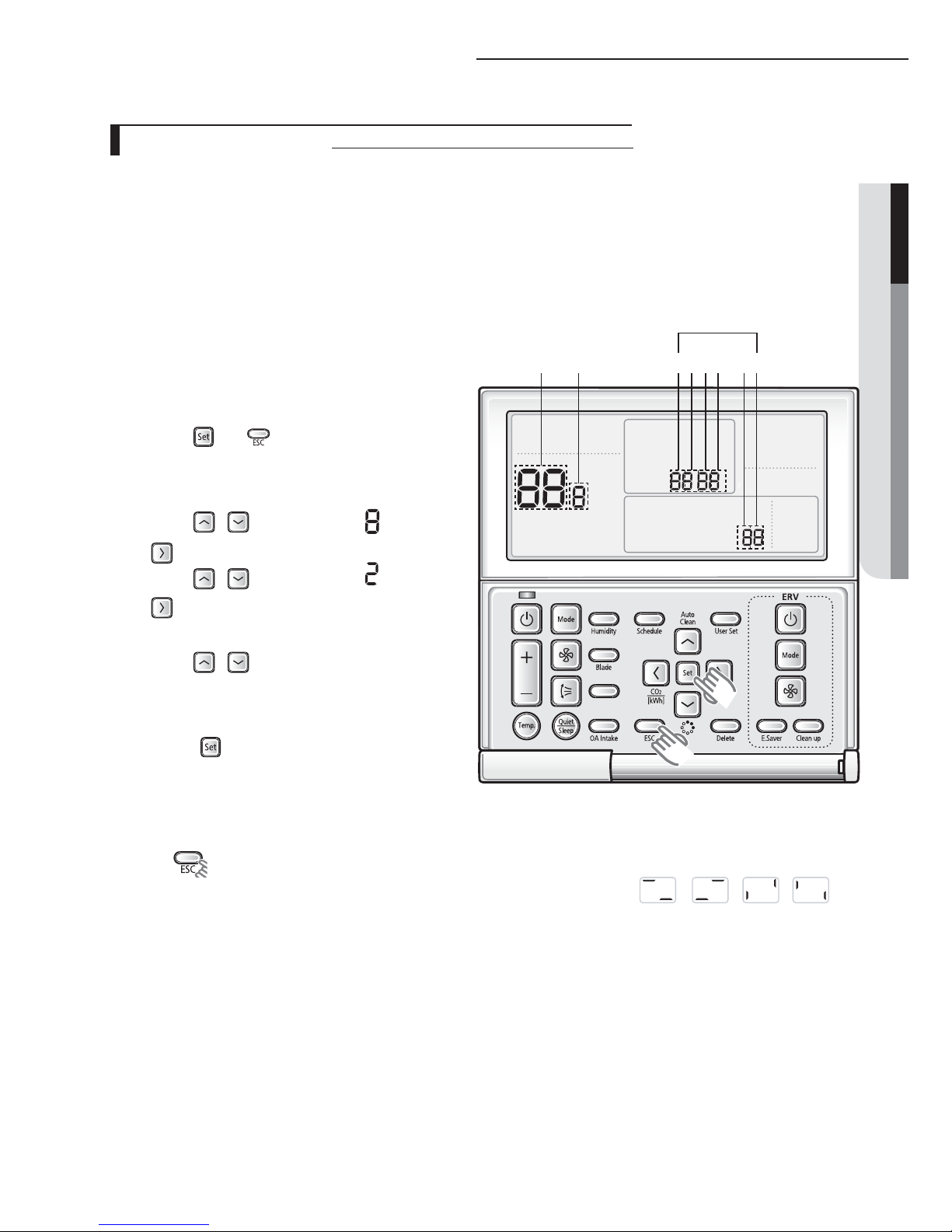
47
A
ENGLISH
Adjusting air ow
Automatic Air-Volume
"XBZ.%4
Main Menu
Sub-menu
123 546
SEG Used
1).Press the and buttons at the same time for
more than 3 seconds and then a Main menu will be
displayed.
2).Press the
/ button to select and then
press
button to enter a Sub-menu setting screen.
3).Press the
/ button to select and then
press
button to enter a automatic air-volume
setting screen.
4).Press the
/ button to select 1 to enable
automatic air-volume operation.
5). Select mode No. 8.2, and set to “1”.
6). Press the
button, then the air conditioning
unit will start the fan operation for Automatic Air-
When multi indoor units are installed, Automatic Air-Volume function cannot be performed simultaneously for all
indoor units. Automatic Air-Volume function must be performed for each indoor unit with the wired remote control attached.
With its BLDC motor, you can use smart adjust the indoor unit fan speed depending on the installation condition.
If the external static pressure is high so that the duct becomes longer or if the external static pressure is low so that
the duct becomes shorter, Using the Automatic Air-Volume function,the volume of exhaust air has been adjusted
to the rated volume flow rate automatically.
Performing the Automatic Air-Volume function.
- Check the air conditioning unit stop.
Press the Power button to stop the air conditioner
- Go to Service setting mode with remote controller.
Volume adjustment.
❈ Do not adjust the dampers during fan operation for Automatic Air-Volume adjustment.
7). Press
button to escape setting mode.
(During the automatic air-volume adjustment,[Main Menu] will be displayed
ttt
repetitively)
8). After 1 to 8 minutes, the air conditioning unit stops operating automatically when Automatic Air-
Volume adjustment has been carried out (fan operation icon will be o.)
(AM77MNMD777/AM77MNHD777)
Page 49
48
A
Adjusting air ow
Main menu Sub menu Functions SEG used Default Range
8
1
Automatic Air-Volume
State Return
10
0 - OFF (Fail or Disable)
1 - Completion.
2 - Running Automatic Air-Volume.
2
Automatic Air-Volume
Operation
10
0 - Disable
1 - Enable
9). When the air conditioning unit has stopped, check the Mode No. 8.1 is "1” for completion of Automatic
Air-Volume.
If the Mode No. 8.1 is “0”, Automatic Air-Volume adjustment is fail. Then adjust the fan speed by referring the
E. S. P(External Static Pressure) setting table.
t
If the
coil is not dry,
run the unit for 2 hours with fan only to dry the coil.
t
The air filter is properly attached into the air passage on the air suction side of the air conditioning
unit.
t Adjust the dampers so that each air inlet and outlet exhusts the designed airow rate.
t If using booster fans(an outdoor air processing unit or ERV via duct), do not use Automatic Air-
Volume function.
t If the duct congurations have been changed, automatic air-volume function perform again.
Page 50
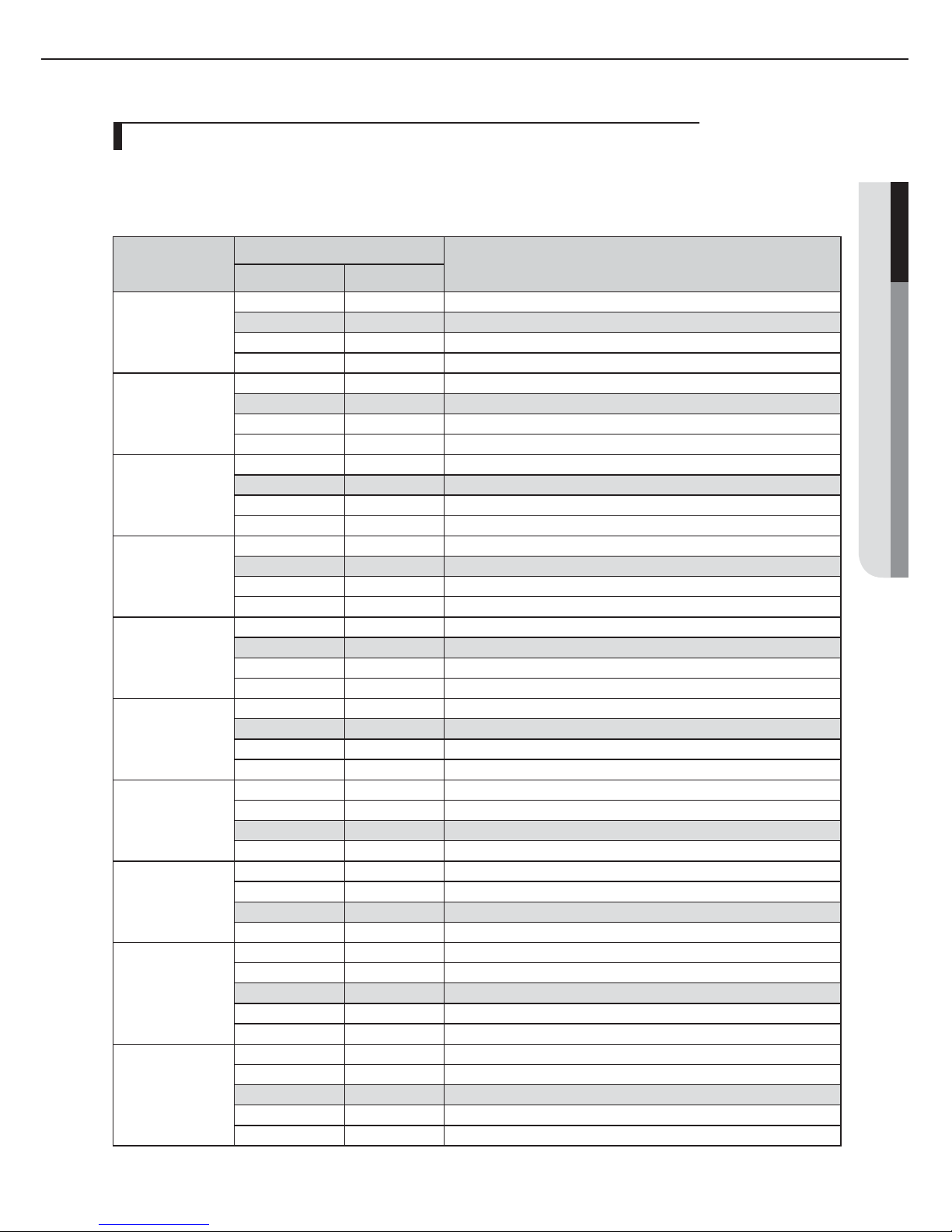
49
ENGLISH
With its phase control motor,you can adjust the indoor unit fan speed depending on the installation condition.
If the external static pressure is high so that the duct becomes longer or if the external static pressure is low
so that the duct becomes shorter,adjust the fan speed by referring the following table.
Model
Static Pressure
Option code
InH2O mmAq
AM007FNLD7
0 0 010054-1254AE-201616-331110
0.04 1 010054-1255D1-201616-331110
0.08 2 010054-1255D1-201616-331110
0.16 4 010054-125904-201616-331110
AM009FNLD7
0 0 010054-121913-201C1C-331110
0.04 1 010054-121946-201C1C-331110
0.08 2 010054-121946-201C1C-331110
0.16 4 010054-121979-201C1C-331110
AM012FNLD7
0 0 010054-121946-202323-331110
0.04 1 010054-121979-202323-331110
0.08 2 010054-121979-202323-331110
0.16 4 010054-1219AC-202323-331110
AM018FNLD7
0 0 010054-1259BA-203434-331110
0.04 1 010054-1259ED-203434-331110
0.08 2 010054-1259ED-203434-331110
0.16 4 010054-125E10-203434-331110
AM024FNLD7
0 0 010054-125D2D-204848-331110
0.04 1 010054-125E50-204848-331110
0.08 2 010054-125E50-204848-331110
0.16 4 010054-125E83-204848-331110
AM030FNLD7
0 0 010054-1B5915-205A5A-331110
0.04 1 010054-1B5948-205A5A-331110
0.12 3 010054-1B599F-205A5A-331110
0.24 6 010054-1B5AE4-205A5A-331110
AM036FNLD7
0 0 010054-1B5956-206E6E-331110
0.04 1 010054-1B5989-206E6E-331110
0.12 3 010054-1B5AD0-206E6E-331110
0.24 6 010054-1B5E25-206E6E-331110
AM048FNLD7
0 0 010054-1B59B9-209191-331110
0.04 1 010054-1B59EC-209191-331110
0.12 3 010054-1B5E33-209191-331110
0.24 6 010054-1B5E88-209191-331110
AM018FNMD7
0 0 010054-125571-203434-331110
0.08 2 010054-125593-203434-331110
0.16 4 010054-1255C5-203434-331110
0.24 6 010054-1255F5-203434-331110
0.32 8 010054-125957-203434-331110
AM024FNMD7
00
010054-125904-204848-331110
0.08 2 010054-125936-204848-331110
0.16 4 010054-125979-204848-331110
0.24 6 010054-125DF9-204848-331110
0.32 8 010054-125DFC-204848-331110
E.S.P(External Static Pressure)setting for phase control motor
Page 51
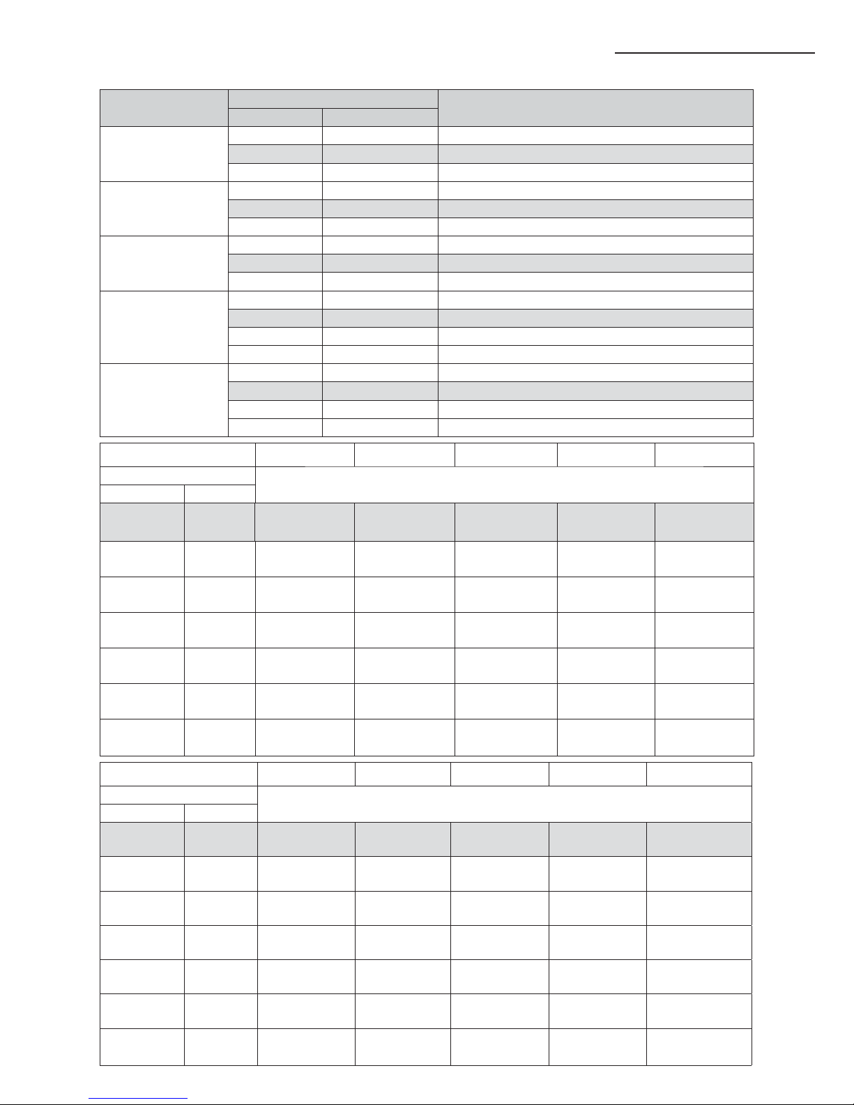
50
A
Model
Static Pressure
Option code
InH2O mmAq
AM030FNMD
7
0.24 6 010054-1259CE-205A5A-331110
0.32 8 010054-125E02-205A5A-331110
0.40 10 010054-125E46-205A5A-331110
AM036FNMD
7
0.24 6 010054-125E00-206E6E-331110
0.32 8 010054-125E44-206E6E-331110
0.40 10 010054-125E88-206E6E-331110
AM048FNMD
7
0.24 6 010054-125E20-209191-331110
0.32 8 010054-125E43-209191-331110
0.40 10 010054-125E86-209191-331110
AM036FNHD
7
0.20 5 010054-135A50-206E6E-331110
0.40
10 010054-135AD7-206E6E-331110
0.60 15
010054-135E5F-206E6E-331110
0.80 20
010054-135F96-206E6E-331110
AM048FNHD
7
0.20 5 010054-135AC3-209191-331110
0.40
10 010054-135E6A-209191-331110
0.60 15
010054-135FA3-209191-331110
0.80 20
010054-135FC8-209191-331110
Adjusting air ow(Contiued)
Model
AM007JNMDCH AM009JNMDCH AM012JNMDCH AM015JNMDCH AM018JNMDCH
Static Pressure
Option code
InH2O mmAq
0<SP≤0.04 0<SP≤1
010054-1B5095-
201616-331110
010054-1B5096-
201C1C-331110
010054-1B50A6-
202323-331110
010054-1B50F9-
202C2C-331110
010054-1B542C-
203535-331110
0.04<SP≤0.12 1<SP≤3
010054-1B50F8-
201616-331110
010054-1B50FA-
201C1C-331110
010054-1B5409-
202323-331110
010054-1B544D-
202C2C-331110
010054-1B5570-
203535-331110
0.12<SP≤0.20 3 <SP≤5
010054-1B544B-
201616-331110
010054-1B544D-
201C1C-331110
010054-1B545C-
202323-331110
010054-1B5580-
202C2C-331110
010054-1B55B4-
203535-331110
0.20<SP≤0.30 5<SP≤7.5
010054-1B549E-
201616-331110
010054-1B5591-
201C1C-331110
010054-1B54AF-
202323-331110
010054-1B55D3-
202C2C-331110
010054-1B5907-
203535-331110
0.30<SP≤0.40 7.5<SP≤10
010054-1B55D1-
201616-331110
010054-1B55E4-
201C1C-331110
010054-1B55F2-
202323-331110
010054-1B5915-
202C2C-331110
010054-1B594A-
203535-331110
0.40<SP≤0.50 10<SP≤12.5
010054-1B5913-
201616-331110
010054-1B5917-
201C1C-331110
010054-1B5934-
202323-331110
010054-1B5968-
202C2C-331110
010054-1B599D-
203535-331110
0.50<SP≤0.60 12.5<SP≤15
010054-1B5956-
201616-331110
010054-1B595A-
201C1C-331110
010054-1B5967-
202323-331110
010054-1B59AB-
202C2C-331110
010054-1B5AD0-
203535-331110
Model
AM024JNHDCH AM027JNHDCH AM030JNHDCH AM036JNHDCH AM048JNHDCH
Static Pressure
Option code
InH2O mmAq
0.12<SP≤0.20 3<SP≤5.2
010054-1355A6-
204646-331110
010054-1355C7-
204F4F-331110
010054-1355D8-
205858-331110
010054-135919-
206969-331110
010054-135A82208D8D-331110
0.20<SP≤0.30 5.2<SP≤7.5
010054-1355F9-
204646-331110
010054-13591C-
204F4F-331110
010054-13593A-
205858-331110
010054-135A70-
206969-331110
010054-135AC5208D8D-331110
0.30<SP≤0.40 7.5<SP≤10
010054-13594E-
204646-331110
010054-13595F-
204F4F-331110
010054-13598E-
205858-331110
010054-135AB4-
206969-331110
010054-135E18-
208D8D-331110
0.40<SP≤0.50 10<SP≤12.5
010054-135A70-
204646-331110
010054-135A93-
204F4F-331110
010054-135AB1-
205858-331110
010054-135AF7-
206969-331110
010054-135E5B208D8D-331110
0.50<SP≤0.60 12.5<SP≤15
010054-135AA3-
204646-331110
010054-135AC5-
204F4F-331110
010054-135AF4-
205858-331110
010054-135E39-
206969-331110
010054-135E9F-
208D8D-331110
0.60<SP≤0.70 15<SP≤17.5
010054-135AE6-
204646-331110
010054-135E08-
204F4F-331110
010054-135E37-
205858-331110
010054-135E6C-
206969-331110
010054-135FB2-
208D8D-331110
0.70<SP≤0.80 17.5<SP≤20
010054-135E18-
204646-331110
010054-135E3A-
204F4F-331110
010054-135E59-
205858-331110
010054-135EAF-
206969-331110
010054-135FC5208D8D-331110
Page 52
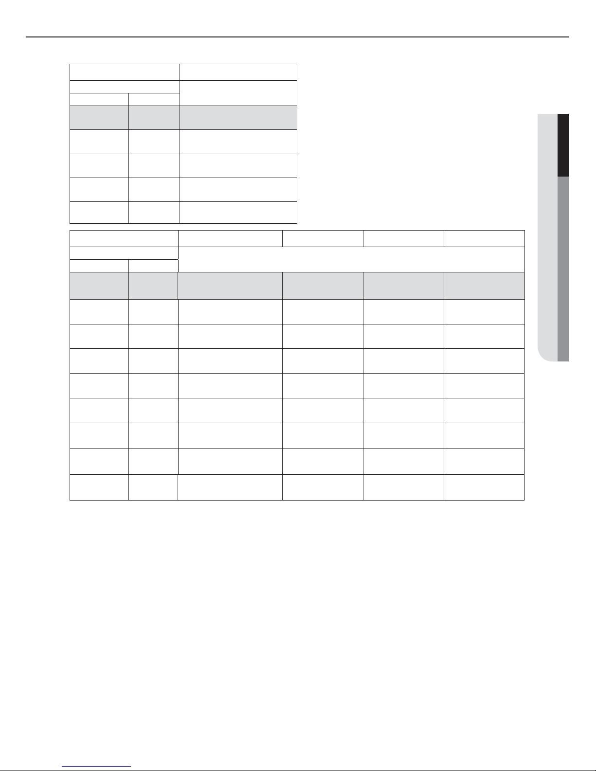
51
ENGLISH
Model
AM006JNMPCH AM018JNMPCH AM028JNMPCH AM042JNMPCH
Static Pressure
Option code
InH2O mmAq
0<SP≤0.04 0<SP≤1
010054-1B5095-
201212-331110
010054-135530-
203535-331110
010054-135585-
205252-331110
010054-1355F9-
207B7B-331110
0.04<SP≤0.12 1<SP≤3
010054-1B50F8-
201212-331110
010054-135552-
203535-331110
010054-135596-
205252-331110
010054-13590B-
207B7B-331110
0.12<SP≤0.20 3 <SP≤5
010054-1B544B-
201212-331110
010054-135585-
203535-331110
010054-1355C9-
205252-331110
010054-13593C-
207B7B-331110
0.20<SP≤0.30 5<SP≤7.5
010054-1B549E-
201212-331110
010054-1355C7-
203535-331110
010054-13591A-
205252-331110
010054-135A60-
207B7B-331110
0.30<SP≤0.40 7.5<SP≤10
010054-1B55D1-
201212-331110
010054-13592A-
203535-331110
010054-13597E-
205252-331110
010054-135AB4-
207B7B-331110
0.40<SP≤0.50 10<SP≤12.5
010054-1B5913-
201212-331110
010054-13594C-
203535-331110
010054-135AA1-
205252-331110
010054-135AF7-
207B7B-331110
0.50<SP≤0.60 12.5<SP≤15
010054-1B5956-
201212-331110
010054-135A80-
203535-331110
010054-135AE1-
205252-331110
010054-135E4A-
207B7B-331110
0.60<SP≤0.70 15<SP≤17.5 -
010054-135AB3-
203535-331110
010054-135E26-
205252-331110
010054-135E5D-
207B7B-331110
0.70<SP≤0.80 17.5<SP≤20 -
010054-135AF5-
203535-331110
010054-135E58-
205252-331110
010054-135FA1-
207B7B-331110
Model
AM054JNHDCH
Static Pressure
Option code
InH2O mmAq
0.12<SP≤0.20 3<SP≤5.2
010054-135E07-
209E9E-331110
0.20<SP≤0.30 5.2<SP≤7.5
010054-135E4A-
209E9E-331110
0.30<SP≤0.40 7.5<SP≤10
010054-135E8D-
209E9E-331110
0.40<SP≤0.50 10<SP≤12.5
010054-135FB1-
209E9E-331110
0.50<SP≤0.60 12.5<SP≤15
010054-135FC4-
209E9E-331110
Page 53
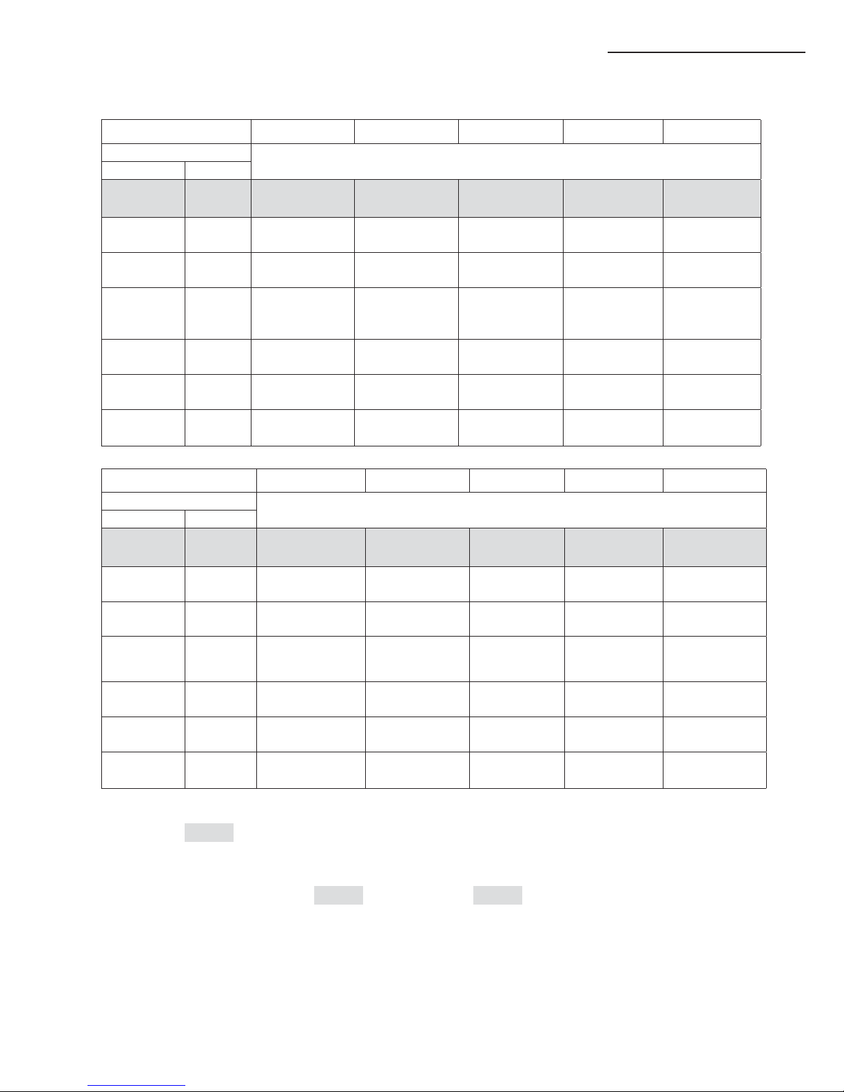
52
A
Note X represents E.S.P(External Static Pressure)range of factory setting.
You don’t have to adjust the fan speed separately if the external static pressure of the
installation place is in
. When it is out of , input the appropriate option code.
X If you input the inappropriate option code,error may occur or the air conditioner is out of order.
The option code must be inputted correctly by the installation specialist or service agent.
Adjusting air ow(Contiued)
Model
AM007MNMDCH AM009MNMDCH AM012MNMDCH
AM015MNMDCH
AM018MNMDCH
Static Pressure
Option code
InH2O mmAq
0≤ SP ≤0.04 0≤ SP ≤1
010054-1E5060-
201616-331101
010054-1E5060201C1C-331101
010054-1E5072-
202323-331102
010054-1E5095202C2C-331103
010054-1E5438-
203535-331104
0.04< SP
≤0.12
1< SP ≤3
010054-1E50D4-
201616-331101
010054-1E50D4-
201C1C-331101
010054-1E50D6-
202323-331102
010054-1E50F9202C2C-331103
010054-1E549B-
203535-331104
0.12< SP
≤0.20
3< SP ≤5
010054-1E5437-
201616-331101
010054-1E5437201C1C-331101
010054-1E5449-
202323-331102
010054-1E545D202C2C-331103
010054-1E54FF-
203535-331104
0.20< SP
≤0.30
5< SP ≤7.5
010054-1E54AA-
201616-331101
010054-1E54AA-
201C1C-331101
010054-1E54BD-
202323-331102
010054-1E55D3202C2C-331103
010054-1E5944-
203535-331104
0.30< SP
≤0.40
7.5< SP
≤10
010054-1E581E-
201616-331101
010054-1E581E201C1C-331101
010054-1E5911-
202323-331102
010054-1E5938202C2C-331103
010054-1E59A9-
203535-331104
0.4< SP ≤0.50
10< SP
≤12.5
010054-1E5972-
201616-331101
010054-1E5972201C1C-331101
010054-1E5976-
202323-331102
010054-1E598C202C2C-331103
010054-1E59EC-
203535-331104
0.5< SP ≤0.60
12.5< SP
≤15
010054-1E59C5-
201616-331101
010054-1E59C5-
201C1C-331101
010054-1E59CA-
202323-331102
010054-1E5AD0202C2C-331103
010054-1E5E30-
203535-331104
Model
AM024MNHDCH AM027MNHDCH AM030MNHDCH AM036MNHDCH AM048MNHDCH
Static Pressure
Option code
InH2O mmAq
0.12≤SP≤0.20 3≤SP≤5.2
010054-1E54BB-
204646-331115
010054-1E55C0-
204F4F-331115
010054-1E55D3-
205858-331116
010054-1E542A-
206969-331124
010054-1E548D208D8D-33112A
0.20< SP≤0.30 5.2< P≤7.5
010054-1E581F-
204646-331115
010054-1E5924-
204F4F-331115
010054-1E5938-
205858-331116
010054-1E546C-
206969-331124
010054-1E55C0208D8D-33112A
0.30< SP≤0.40 7.5<SP≤10
010054-1E5973-
204646-331115
010054-1E5989-
204F4F-331115
010054-1E598C-
205858-331116
010054-1E55B0-
206969-331124
010054-1E55F2208D8D-33112A
0.40< SP≤0.50 10<SP≤12.5
010054-1E59C6-
204646-331115
010054-1E59DC-
204F4F-331115
010054-1E5AE1-
205858-331116
010054-1E55F3-
206969-331124
010054-1E5935208D8D-33112A
0.50< SP≤0.60 12.5<SP≤15
010054-1E5D1A-
204646-331115
010054-1E5E20-
204F4F-331115
010054-1E5E35-
205858-331116
010054-1E5936-
206969-331124
010054-1E5989208D8D-33112A
0.60< SP≤0.70 15<SP≤17.5
010054-1E5D6D-
204646-331115
010054-1E5E63-
204F4F-331115
010054-1E5E78-
205858-331116
010054-1E597A-
206969-331124
010054-1E59CC208D8D-33112A
0.70< SP≤0.80 17.5<SP≤20
010054-1E5EA0-
204646-331115
010054-1E5EB7-
204F4F-331115
010054-1E5ECC-
205858-331116
010054-1E59BD-
206969-331124
010054-1E5D0F208D8D-33112A
Page 54
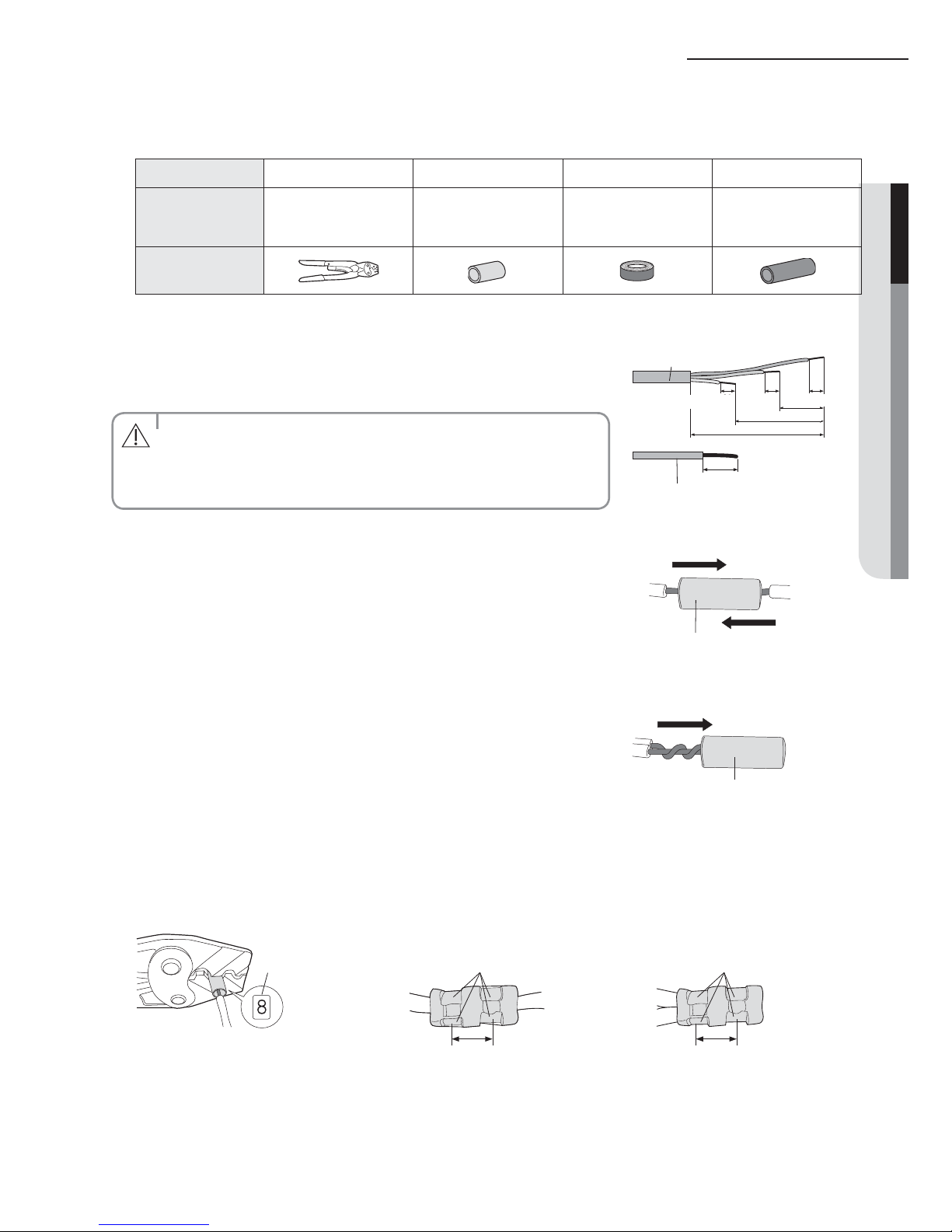
53
A
ENGLISH
Extending the power cable
1. Prepare the following tools.
Tools Crimping pliers Connection sleeve Insulation tape Contraction tube
Spec MH-14
20xØ0.26 inch(6.5
mm)
(HxOD)
Width 0.75 inch(19
mm)
70xØ0.31 inch(8.0
mm)
(LxOD)
Shape
2. As shown in the gure, peel o the shields from the rubber
and wire of the power cable.
- Peel o 0.79 inch(20 mm) of cable shields from the pre-
installed tube.
t For information about the power cable specications for
indoor and outdoor units, refer to the installation manual.
t After peeling o cable wires from the pre-installed tube,
insert a contraction tube.
CAUTION
3. Insert both sides of core wire of the power cable into the
connection sleeve.
f Method 1
Push the core wire into the sleeve from both sides.
Connection sleeve
f Method 2
Twist the wire cores together and push it into the sleeve.
Connection sleeve
4. Using a crimping tool, compress the two points and ip it over and compress another two
points in the same location.
- The compression dimension should be 0.31 inch (8.0 mm).
- After compressing it, pull both sides of the wire to make sure it is rmly pressed.
Compression
dimension
f Method 1
Compress it 4 times.
0.20 inch
(5 mm)
f Method 2
Compress it 4 times.
0.20 inch
(5 mm)
Unit: inch(mm)
120
60
202020
180
Power cable
20
Pre-installed tube for the power cable
0.79 (20)
0.79 (20) 0.79 (20)
2.36 (60)
4.72 (120)
7.09 (180)
0.79 (20)
Page 55
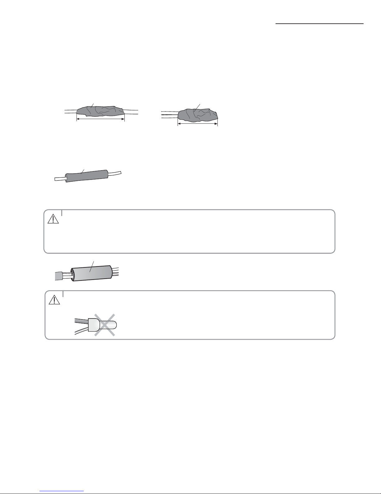
54
A
1. Wrap it with the insulation tape twice or more and position your contraction tube in the
middle of the insulation tape.
Three or more layers of insulation are required.
f Method 1
1.57 inch
(40 mm)
Insulation tape
f Method 2
Insulation tape
1.38 inch
(35 mm)
2. Apply heat to the contraction tube to contract it.
Contraction tube
3. After tube contraction work is completed, wrap it with the insulation tape to nish.
Insulation tape
t In case of extending the electric wire, please DO NOT use a round-shaped Pressing socket.
- Incomplete wire connections can cause electric shock or a re.
WARNING
Extending the power cable
t Make sure that the connection parts are not exposed to outside.
t Be sure to use insulation tape and a contraction tube made of approved reinforced insulating
materials that have the same level of withstand voltage with the power cable. (Comply with
the local regulations on extensions.)
CAUTION
Page 56
55
ENGLISH
Page 57
DB68-07187A-00
 Loading...