

Page 1
3. Operating Instructions and Installation
3-1 Operating Instructions
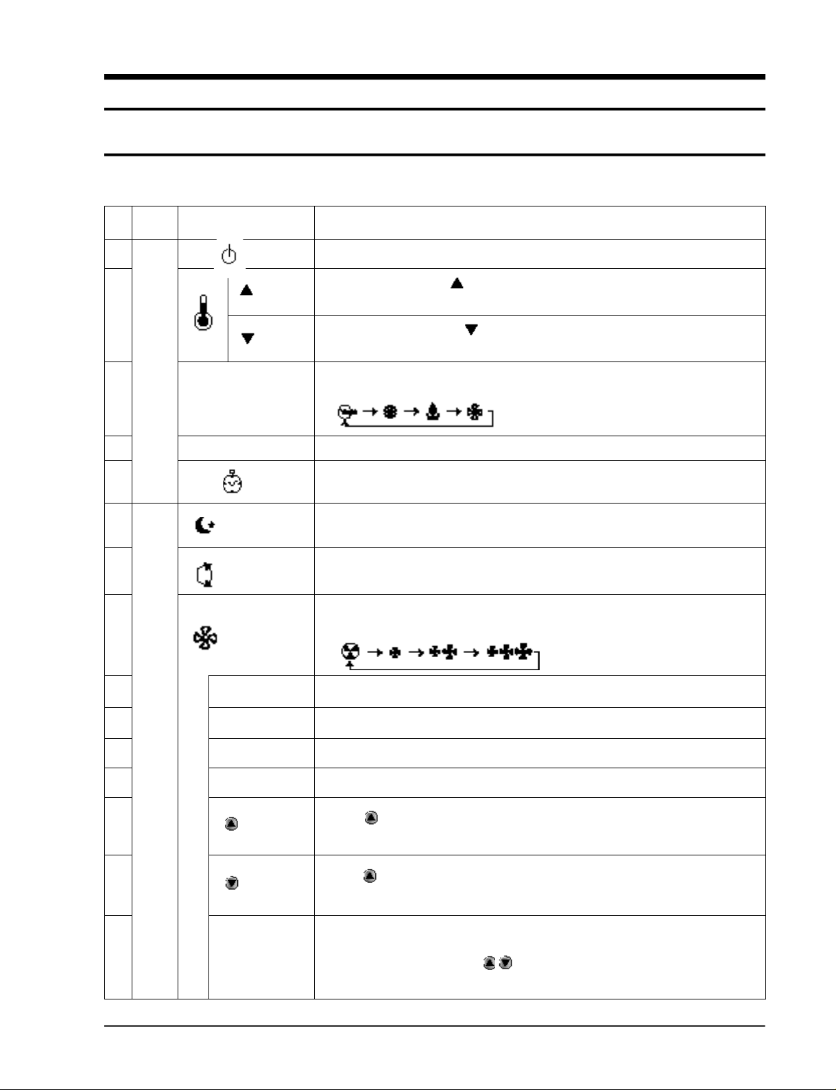
3-1-1 Name & Function of Key in remote controller
NO
NAMED OF KEY
1
2
3
MODE
4
5
6
7
8
TURBO
OFF
(UP)
(DOWN)
On/Off Button. Use this button to start and stop air conditioner.
Temp. up button. If the button is pressed once,
the setting temperature is increased by 1°C
Temp. down button. If the button is pressed once,
the setting temperature is decreased by 1°C
Each time you press this button,
MODE is changed in the following order.
Use this button to provide heavy duty cooling & Heating for 30 minutes.
Set up the reserve or cancel the timer on and timer off quickly
Use this button for sleep operation.
(The SLEEP mode can be selected at COOL and HEAT mode.)
Adjusts air flow vertically.
Each time you press this button,
Each time you press this button,
FAN SPEED is changed in the following order.
FUNCTION OF KEY
9
C
O
10
V
E
R
11
12
13
14
15
Samsung Electronics
T
I
M
E
R
ON TIMER
OFF TIMER
SET
CANCEL
TIME
(UP)
(DOWN)
Set up the time that operation start.
Set up the time that operation stop.
Use this button to reserve the timer on.
Use this button to reserve or cancel the timer on and timer off.
If the button is pressed once, the time increase by one minute
during the time set mode, and ten minutes during the timer set mode.
If the button is pressed once, the time decrease by one minute
during the time set mode, and ten minutes during the timer set mode.
Without regard to ON/OFF condition in remote controller,
use this button to set current time.
Adjust the current time using button.
(Data can be transmitted after setting up the time)
3-1
Page 2
Operating Instructions and Installation
3-1-2 Name & Function of Key in remote controller
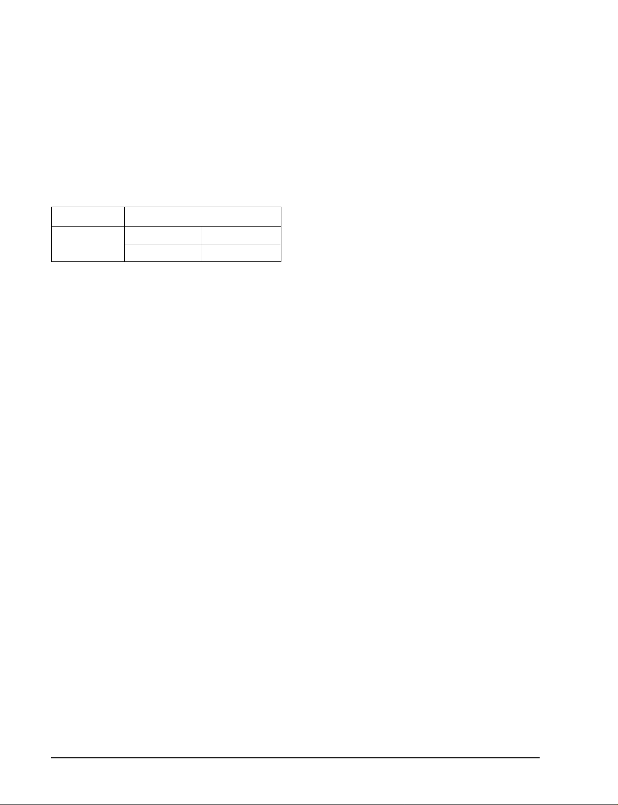
1. A U TO MODE : In this mode, operation
C O O L mode is selected automatically by the
room temperature of initial operation.
Operation Type
Tr≥ 24.5°C+∆T Compressor ON
Cool Operation
Tr≤ 24°C+∆T Compressor OFF
∆T= -2°, -1°C, 0°C+1°C+2°C
∆T is controlled by setting temperature
up/down key of remote contro l l e r
* FAN SPEED : A U TO
2. C O O L MODE : The unit operates accord i n g
to the diff e rence between the setting and
room temperature. (18°C~30°C)
3. D RY MODE : Has 3 states, each determined
by room temperature .
The unit operates in DRY m o d e .
*Co m p ressor ON/OFF Time is contro l l e d
compulsorily(can not set up the fan speed,
always bre e z e ) .
* P rotective function : Low temperature
release. (Prevention against fre e z e )
Room Temp
4. TURBO MODE : This mode is available in
A U TO, COOL, DRY, FAN MODE.
When this button is pressed at first, the air
conditioner is operated “powerful” state for
30 minutes re g a rdless of the set temperat u re, room temperature .
When this button is pressed again, or when
the operating time is 30 minutes, turbo
operation mode is canceled and returned to
the previous mode.
*But, if you press the TURBO button in DRY
or FAN mode that is changed with A U TO
mode automatically.
5 . S L E E P MODE : Sleep mode is available
only in COOL m o d e .
The operation will stop after 6 hours.
*In COOL mode : The setting temperature
is automatically raised by 1°C each 1hour
When the temperature has been raised by
total of 2°C, that temperature is maint a i n e d .
6. FAN SPEED : Manual (3 step), Auto (4 step)
Fan speed automatically varies depending
on both the diff e rence between setting and
the room temperature .
3-2
Samsung Electronics
Page 3
Operating Instructions and Installation
7 . C O M P U L S O RY O P E R ATION :
For operating the air conditioner without
the remote contro l l e r.
* A U TO : The operating is the same function that A U TO MODE in the remote cont ro l l e r.
8 . SWING : BLADE-H is rotated vertically by
the stepping motor.
9 . Quick OFF TIMER: OFF timer (quick timer)
allows reservation or cancel the timer on
and timer off quickly
When OFF timer button is pressed at operating state, LCD displays the polling state
s e q u e n t i a l l y.
The LCD also displays the time re m a i n i n g .
1 0 . 24-Hour ON/OFF Real Setting Ti m e r. : The
air conditioner is turned ON at a specified
time using .
ON TIMER
OFF TIMER : The air Conditioner is turned
OFF at a specified time using .
OFF TIMER
*ON TIMER : Only timer LED lights on.
*OFF TIMER : Both timer and operation
LED lights on.
*3 minutes delay timer.
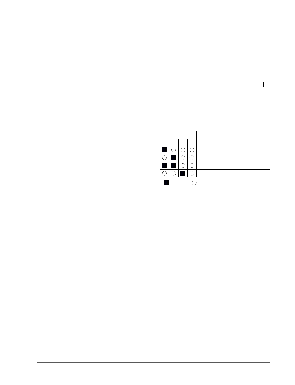
11 . SELF Diagnosis
LED DISPLAY
o p e r-
T I M E R
a t i o n
FA N
Tu r b o
Check Point
I n t e r ruption of electric power and Power on.
Abnormal condition of the room sensor.
Abnormal condition of the indoor unit's heat exchanger sensor.
Indoor unit fan motor lock.
L E D
:
b l i n k i n g
: LED off
1 2 . BUZZER SOUND : Whenever the ON/OFF
button is pressed or whenever change
occurs to the condition which is set up or
select, the compulsory operation mode,
buzzer is sounded "beep"
Samsung Electronics
3-3
Page 4

3-2 Installation
3-2-1 Selecting Area for Installation
Select an area for installation that is suitable
to the customer's needs.
3-2-1(a) Indoor Unit
1 . Make sure that you install the indoor unit in
an area providing good ventilation. It must
not be blocked by an obstacle affecting the
airflow near the air inlet and the air outlet.
2 . Make sure that you install the indoor unit in
an area allowing good air handling and
endurance of vibration of the indoor unit.
3. Make sure that you install the indoor unit in
an area where there is no source of heat or
vapor nearby.
4 . Make sure that you install the indoor unit in
an area from which hot or cool air is spre a d
evenly in a ro o m .
5 . Make sure that you install the indoor unit in
an area away from TVs, audio units, cordless phones, fluorescent lighting fixture s
and other electrical appliances (at least 1
m e t e r ) .
6 . Make sure that you install the indoor unit in
an area which provides easy pipe connection with the outdoor unit, and easy
drainage for condensed water.
7. Make sure that you install the indoor unit in
an area which is large enough to accomodate the measurements shown in figure on
the next page.
3-2-1(b) Outdoor Unit
1 . Make sure that you install the outdoor unit
in area not exposed to the rain or direct sun
l i g h t .
(Install a separate sunblind if exposed to
d i rect sun light.)
2 . Make sure that you install the outdoor unit
in area allowing good air moment, not
amplifying noise or vibration, especially to
avoid disturbing neighbours.
(Fix the unit firmly if it is mounted in a
high place.)
3 . Make sure that you install the outdoor unit
in area providing good ventilation and
which is not dusty. It must not be blocked
by any obstacle affecting the airflow near
the air inlet and the air outlet.
4 . Make sure that you install the outdoor unit
in area free from animals or plants.
5 . Make sure that you install the outdoor unit
in area not blocking the traff i c .
6. Make sure that you install the outdoor unit
in area easy to drain condensed water fro m
the indoor unit.
7. Make sure that you install the outdoor unit
in area which provides easy connection
within the maximum allowable length of a
coolant pipe (10 meters).
N o t e
1. Add 10 grams of refrigerant (R-22) for
every 1 meter if the pipe length exceeds
the standard pipe length of 5 meters.
2. Maintain a height between the indoor and
outdoor units of less than 3 meters.
8 . Make sure that you install the outdoor unit
in an area which is large enough to accommodate the measurements
shown in figure on the next page.
3-2-1(c) Remote Control Unit
1 . Make sure that you install the remote con-
t rol unit in an area free from obstacles such
as curtains etc, which may block signals
f rom the remote control unit.
2. Make sure that you install the remote cont rol unit in an area not exposed to
d i rect sunlight, and where there is no sourc e
of heat.
3. Make sure that you install the remote cont rol unit in an area away from TVs, audio
units, cordless phones, fluorescent lighting
f i x t u res and other electrical appliances (at
least 1 meter).
Caution
It is harmful to the air conditioner if it is used in the following environments: greasy areas (including areas near machines),
salty areas such as coast areas, areas where sulfuric gas is present such as hot spring areas. Contact your dealer for advice.
3-4
Samsung Electronics
Page 5
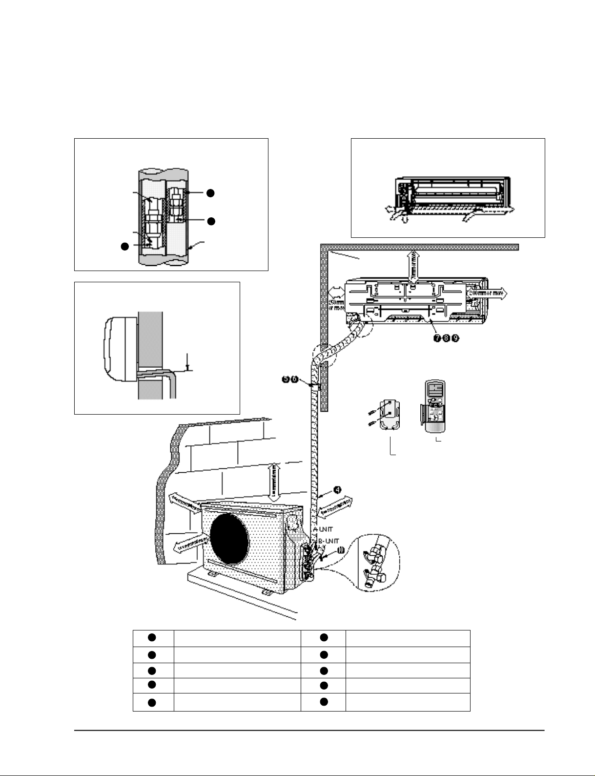
3-2-2 Installation diagram of indoor unit and outdoor unit
Operating Instructions and Installation
A Indoor unit gas leak test check point
Indoor unit
Piping
1
3
2
Tape vinyl
B Drain hose installation
Cut the piping hole
sloped slightly
Piping may be laid to the rear, left,
right or down .
Right
Rear
Down
Rear
Left
Remote control
Remote control holder
1
2
3
4
5
Piping (Liquid) 1/4" Clamper tube
Piping (Gas) 1/2" Installation plate
Installation tube Pipe-connection
Vinyl tape Screw
Putty Drain hose
6
7
8
9
10
Samsung Electronics
3-5
Page 6

Operating Instructions and Installation
3-2-2(a) Fixing the Installation Plate
(Unit : mm)
(Unit : mm)
Installation plate
280
340
Pipe hole
(ø65mm)
1. Determine the position of the pipe and drain hose hole
using the right figure and drill the hole with an inner
diameter of 65mm so that it slants slightly downwards.
2. If you are fixing the indoor unit to a… Then follow Steps…
Wall 3.
Window frame 4 to 6.
3. Fix the installation plate to the wall in a manner appropriate to the weight of the indoor unit.
If you are mounting the plate on a concrete wall with
anchor bolts, the anchor bolts must not project by more
than 20mm.
4. Determine the positions of the wooden uprights to be
attached to the window frame.
3-2-2(b) Purging the Unit
5. Attach the wooden uprights to the window frame in a
manner appropriate to the weight of the indoor unit.
6. Using tapped screws, attach the installation plate to the
wooden uprights, as illustrated in the last figure opposite.
On delivery, the indoor unit is loaded with an inert gas.
All this gas must therefore be purged before connecting the
assembly piping. To purge the inert gas, proceed as fol lows.
Unscrew the caps at the end of each pipe.
Result : All inert gas escapes from the indoor unit.
• To prevent dirt or foreign objects from getting into
the pipes during installation, do NOT remove the
caps completely until you are ready to connect the
piping.
3-6
Samsung Electronics
Page 7

3-2-2(c) Connecting the Assembly Cable.
The outdoor unit is powered from the indoor unit via the assembly
cable. If the outdoor unit is more than five metres away from the
indoor unit, the cable must first be extended to a maximum of
ten metre s .
1 . Extend the assembly cable if necessary.
2 . Open the front grille by pulling on the tabs on the lower right and
left sides of the indoor unit.
3 . Remove the screw securing the connector cover.
4 . Pass the assembly cable through the rear of the indoor unit and
connect the assembly cable to terminals 1 to 5.
• Each wire is labelled with the corresponding terminal number.
5 . Pass the other end of the cable through the 65mm hole in the wall.
6 . Replace the connector cover, carefully tightening the scre w.
7 . Close the front grille.
8 . For further details on how to plug the other end of the assembly
cable into the outdoor unit, refer to page 3-10.
Operating Instructions and Installation
3-2-2(d) Installing and Connecting the Indoor Unit Drain Hose
C a re must be taken when installing the drain hose for the indoor unit to ensure that any condensa tion water is correctly drained outside.l When passing the drain hose through the 65mm hole drilled
in the wall, check that none of the following situations occur.
The hose must
NOT slope upw
ards.
To install the drain hose, proceed as follows.
1. If necessary, connect the 2-metre extension to the drain hose.
2 . If you are using the extension, insulate the inside part of the extension drain hose with a shield.
3. Pass the drain hose under the refrigerant piping, taking care to keep the drain hose tight.
4. Pass the drain hose through the hole in the wall, making sure that it is sloping downwards, as
shown in the illustrations above.
The end of the drain
hose must NOT be
placed in water.
Do NOT bend the
hose in different
directions.
Keep a clearance of at
least 5cm between the
end of the hose and the
ground.
Do NOT place the end
of the drain hose in a
hollow.
Shield
Drain hose Extension drain hose
Samsung Electronics
The hose will be fixed permanently into position once
the whole installation has been tested for gas leaks;
refer to page 16 for further details.
3-7
Page 8

Operating Instructions and Installation
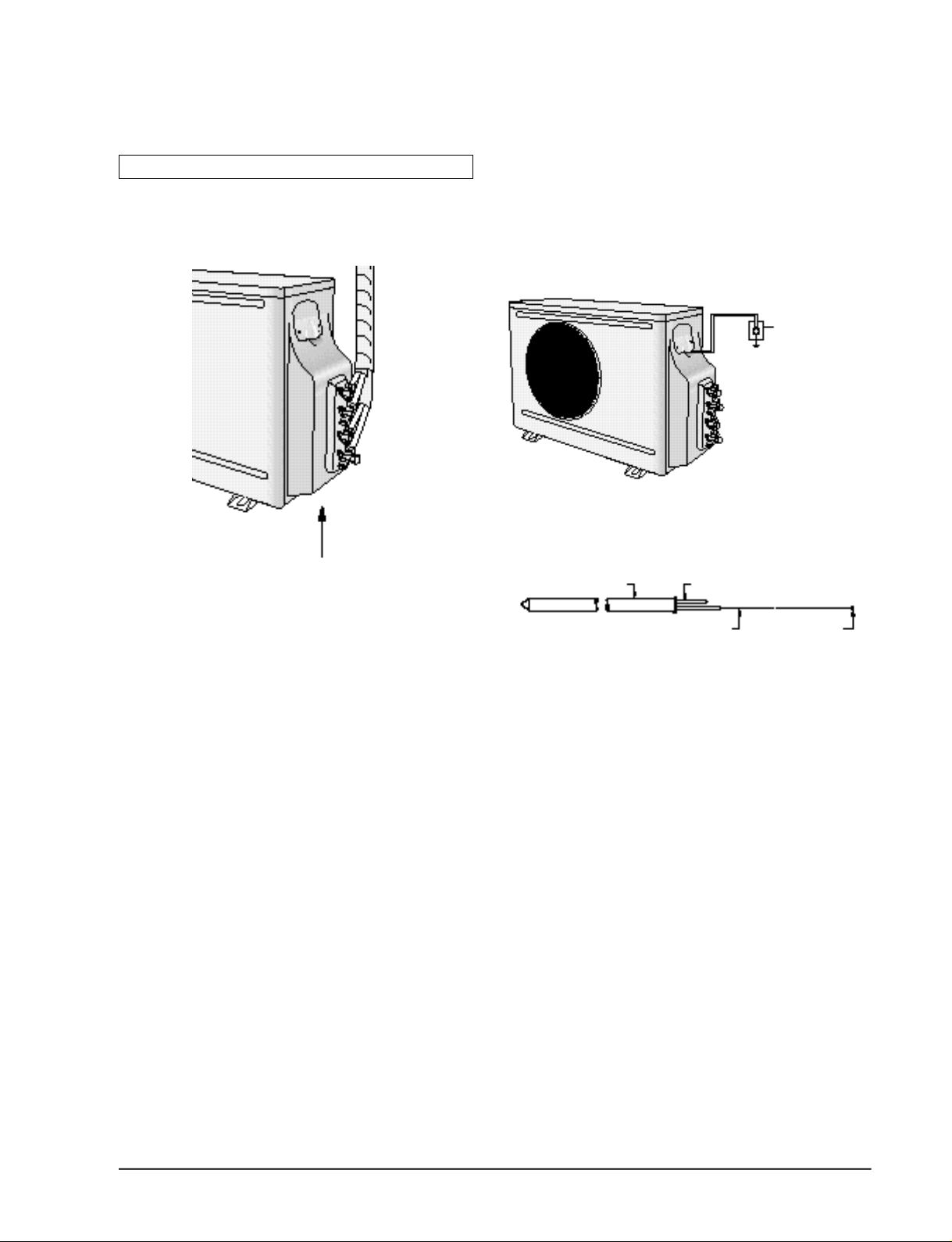
3-2-2(e) Outdoor unit installation
GAS LEAK TEST
Indoor unit check point
Check for gas leak from the flare nut connections with leak detector.
WIRING CONNECTION
Two electric cables must be connected to the outdoor unit:
• The assembly cable connecting the indoor unit to the outdoor unit.
• The power cable connecting the auxiliary circuit breaker to the outdoor unit.
1 Remove the terminal board cover on the side of the outdoor unit.
Outdoor unit check point
2 Connect the assembly cable to terminals 1 to 5 and connect the power cable to therminals A to B.
Each wire is labelled with the corresponding terminal number.
E n s u re that the wire number of the indoor unit and the terminal number of the out-
door unit.
3 Connect the earthing wires to the earth terminals.
Refer to the page opposite for further details on how to check that earthing is corre c t .
4 Replace the terminal board cover, carefully tightening the screw.
5 connect the power cable to the auxiliary circuit breaker.
Indoor unit
Outdoor unit Terminal Block
4
FAN
3
COMP
2
1
(N)
(L)
3
COMP
FAN
4
1(L) 2(N)
Earth
terminal
Circuit Breaker
(Main Power cable)
3-8
A-unit
Earth
terminal
Earth
terminal
B-unit
Samsung Electronics
Page 9
Grounding
Operating Instructions and Installation
(The parts for this work are optional.)
• A g rounding terminal can be found on
the outdoor unit as illustrated.
Grounding screw hole
1. When an existing grounding terminal is
a v i l a b l e .
( G rounding wire of ø1.6mm or larg e r < s o l i d
w i re>or 2mm2or larger <standard wire>)
Terminal used
exclusively for
grounding.
Grounding resistance:
less than 100 ohms
(existing grounding electrode)
2 . Use of a grounding electro d e .
• Specifications of grounding electro d e .
Carbon plastic Steel core
PVC-insulated wire(2mm2x3.5m), green Terminal, M4
Samsung Electronics
3-9
Page 10

Operating Instructions and Installation
3-2-2(f) Flare Modification
• Tools used
Flare modification procedure
1 ) Cut the pipe using a pipe cutter.
90°
3 ) Insert a flare nut into the pipe and modifty flare .
Oblique
Raughness
2 ) Remove burrs at the tip of the pipe cut.
Burr
* Unproper flaring
C a u t i o n : Burrs not removed may result in
leakage of gas.
Pipe
Reamer
D
A
Outer diameter A(mm)
ø6.35mm 1.3
ø9.52mm 1.8
ø12.7mm 2.0
3-10
Inclined Surface
damaged
Cracked Uneven
thickness
Samsung Electronics
Page 11

Operating Instructions and Installation
3-2-2(g) Air Purging
CAUTION
The air in indoor unit and in the pipe must be purged. If air remains in the refrigeration pipes, it will affect the compressor,
reduce to cooling/heating capacity, and could lead to a malfuction. Refrigerant for air purging is not charged in the outdoor unit.
Use additional refrigerant as shown at the right figure. Each unit must be purged in turn
1. Check the piping connections
2. Connect the charging hose of low pressure side of
Manifold gauge to the packed valve having a charging
port(1/2” Packed valve)
3. Open the valve of the low pressure side of Manifold
gauge counterclockwise for 10 seconds, and then close
it to closed position.
4. Check for gas leakage.
-Check the flare connections for gas leakage.
5. Purge the air from the system.
-Loosen the liquid side(1/4”) flare nut after gas leakage
check
-Open the low pressure side valve of the Manifold
gauge for 10 seconds to purge the air from the system.
Repeat this three times or more.
-Tighten the liquid side(1/4”) flare nut when the low
pressure of the manifold gauge indicates about
0.5Kg/cm2.
6. Set valve cork of both liquid side and gas side of
packed valve to the open position.
7. Mount the valve stem nuts to the 2-way and 3-way
valve. And mount the service port cap to 3-way valve
8. Check for gas leakage.
-At this time, especially check for gas leakage from the
3-way valve’s stem nuts, and from the service port cap.
INDOOR
A-UNIT
INDOOR
B-UNIT
liquid side
Gas side
Pipeline
Flare Nut
Valve cork
Pipeline
Outdoor
unit
Charging Port
Charging hose of
Low pressure hose
Samsung Electronics
<Structure of 3-way valve>
3-11
Page 12

Operating Instructions and Installation
3-2-2(h) Refrigerant Refill
If connecting pipe of more than 10 metres is installed, additional refrigerant should be charged by
extra metre. You don’t have to charge additional refrigerant up to 10 metres of connecting pipe.
1. Remove the valve stem cap and service port of 3-way
valve.
2. Connect the charging hose of low pressure side of
Manifold gauge to the packed valve having a charging
port(1/2” Packed valve) as shown at the right figure.
3. Operate the unit at the cooling mode.
4. Slowly open the valve of the low pressure side of
Manifold gauge counterclockwise until the low pressure of manifold gauge indicates 4.8 to 5.5 kg/cm2at
the high cool operation (1-unit operation) and the standard temperature.(for details, see the page 3-14)
It is recommend that refrigerant should be slowly put
in. If the refrigerant is put in too quickly, compressor
will be damaged.
• Piping length and the height
Pipe Size
Max.piping
length
A
A-UNIT
B-UNIT
Additional refrigerant charg e
( R 2 2 , g )
• When length of the pipe is
over 5u by the unit, you
should charge
the refrigerant Formulas
A-UNIT : 10gx(La-10)/m
B-UNIT : 10gx(Lb-10)/m
(La:the length of A-unit’s
pipe Lb:the total length of
B-unit’s pipe)
1/4” 1/2”
1/4” 1/2”
15m
15m
INDOOR UNIT
Max
height
BLIQUID GAS
3m
3m
A
B
OUTDOOR UNIT
5. Stop operation of the air conditioner.
6. Disconnect the charge hose of manifold gauge.
7. Close the cap of each valve.
3-2-2(i) Flare unt fixing torque
Outter diameter
Fixing Torque Final Torque
ø6.35(Liquid Side) 160 200
ø12.7(Gas Side) 500 550
3-12
Torque (kg-cm)
INDOOR
A-UNIT
INDOOR
B-UNIT
Samsung Electronics
Page 13

3-2-2(j) Pump down
1 . Confirm that both the 2-way and 3-way valves are
set to the open position.
(1) Remove the valve stem caps.
(2) Be sure to use a hexagonal wrench to operate
the Gas side valve stems.
2 . Operate the unit for 10 to 15 minutes.
3 . Stop operation and wait for 3 minutes, then con-
nect the charge set to the service port of the 3-way
v a l v e .
(1) Connect the charge hose with the push pin to
the service port.
Operating Instructions and Installation
2-Way Valve
4 . Air purging of the charge hose.
(1) Open the low-pre s s u re valve on the charge set
slightly to air purge from the charge hose.
5 . Set the liquid side 2-way valve to the closed posi-
t i o n .
6 . Operate the air conditioner at the cooling cycle
and stop operation immediately after setting the
3-way valve to the closed position when the
gauge indicates 0 kg/cm2G .
If the unit can not be operated at the Cooling
Mode(weather is rather cool), operate the unit at
the Trubo Mode. So that the unit can be operated.
7 . Disconnect the charge set, and mount the both 3-
way valve’s stem nuts and the service port cap.
Relocation of the air conditioner
• Refer to this pr o c e d u re when the unit is r e l o c a t e d .
1. Carry out the pump down pro c e d u re
( refer to the details of ‘pump down’).
2. Remove the power cord .
3. Disconnect the assembly cable from the
indoor and outdoor units.
4. Remove the flare nut connecting the indoor
unit and the pipe.
At this time, cover the pipe of the indoor
unit and the other pipe using a cap or vinyl
plug to avoid foreign material entering.
Cap
3-Way Valve
5. Disconnect the pipe connected to the outdoor
u n i t .
At this time, cover the valve of the outdoor
unit and the other pipe using a cap or vinyl
plug to avoid foreign material entering.
6. Make sure you do not bend the connection
pipes in the middle and store together with
the cables.
7. Move the indoor and outdoor units to a new
l o c a t i o o n .
8. Remove the mounting plate for the indoor
unit and move it to a new location.
Samsung Electronics
3-13
Page 14

Operating Instructions and Installation
3-2-3 Technical Document
• Cooling Characteristics - Outdoor Te m p e r a t u re
Indoor Unit(D/WB) : AM24A1(B1)E12 : 27/19, AM26A1(B1)B13 : 27/19.5
AM24A1(B1)E2 : 240V/50Hz, AM26A1(B1)B2 : 220V/60Hz
Cooling Capacity & Air Outlet Temperature
Cooling Capacity (AM24A1(B1)E12)
Air Outlet Temp. (AM24A1(B1)E12)
15000
14000
13000
12000
11000
21/15(15.5)
Current & Low Pressure
Cooling Capacity (AM24A1(B1)E12)
Low Pressure (AM24A1(B1)E12)
Cooling Capacity (AM26A1(B1)B13)
Air Outlet Temp. (AM26A1(B1)B13)
15
14
13
12
11
10
21/19(19.5) 35/24 43/26(25.5)
Outdoor Temperature(DB/WB)
Cooling Capacity (AM26A1(B1)B13)
Low Pressure (AM26A1(B1)B13)
3-14
15000
14000
13000
12000
11000
8
7
6
5
4
3
21/15(15.5) 21/19(19.5) 35/24 43/26(25.5)
Outdoor Temperature(DB/WB)
Samsung Electronics
 Loading...