

Samsung AM0 SERIES, JNZDCHAA Installation Manual
AM0**JNZDCH/AA IM ENG_V1.5_07082015
Multiposition AHU
AM0✴✴JNZDCH/AA
Air Conditioner
installation manual
EN
imagine the possibilities
Thank you for purchasing this Samsung product.
AM0**JNZDCH/AA IM ENG_V1.5_07082015
1

ENGLISH
Contents
Safety Precautions
(Carefully follow the precautions listed below because they are essential to guarantee the safety of the equipment.)
WARNING
• Always disconnect the air conditioner from the power supply before servicing it or
accessing its internal components.
• Verify that installation and testing operations are performed by qualified personnel.
• Verify that the air conditioner is not installed in an easily accessible area.
General information
X Carefully read the content of this manual before installing the air conditioner and store the manual in a safe place in
order to be able to use it as reference after installation.
X For maximum safety, installers should always carefully read the following warnings.
X Store the operation and installation manual in a safe location and remember to hand it over to the new owner if the
air conditioner is sold or transferred.
X This manual explains how to install an indoor unit with a split system with SAMSUNG units. The use of other
types of units with different control systems may damage the units and invalidate the warranty. The manufacturer
shall not be responsible for damages arising from the use of non compliant units.
X The manufacturer shall not be responsible for damage originating from unauthorized changes or the improper
connection of electric and hydraulic lines. Failure to comply with these instructions or to comply with the
requirements set forth in this manual, shall immediately invalidate the warranty.
X The air conditioner should be used only for the applications for which it has been designed: the indoor unit is not
suitable to be installed in areas used for laundry.
X
Do not use the units if damaged. If problems occur, switch the unit off and dis
connect it from the power supply.
X
I
n order to prevent electric shocks, fi
re or injuries, always stop the unit, disable the protection switch and contact
SAMSUNG’s technical support if the unit produces smoke, if the power cable is hot or damaged or if the unit is very noisy.
Refrigerant piping . ........................................... ................... ...................12
Performing leak test and insulation . ............................... .................................... .13
Additional refrigerant . ...............................................................................15
Drain pipe installation . ...............................................................................16
Wiring work . . . . . . . . . . . . . . . . . . . . . . . . . . . . . . . . . . . . . . . . . . . . . . . . . . . . . . . . . . . . . . . . . . . . . . . . . . . . . . . . . . . . . . . . . . . . . . . . . . . . 18
Wire diagram . . . . . . . . . . . . . . . . . . . . . . . . . . . . . . . . . . . . . . . . . . . . . . . . . . . . . . . . . . . . . . . . . . . . . . . . . . . . . . . . . . . . . . . . . . . . . . . . . . 26
Selecting motor speeds . . . . . . . . . . . . . . . . . . . . . . . . . . . . . . . . . . . . . . . . . . . . . . . . . . . . . . . . . . . . . . . . . . . . . . . . . . . . . . . . . . . . . . . . . 28
Blower CFM tables . . . . . . . . . . . . . . . . . . . . . . . . . . . . . . . . . . . . . . . . . . . . . . . . . . . . . . . . . . . . . . . . . . . . . . . . . . . . . . . . . . . . . . . . . . . . . 29
Setting an indoor unit address and installation options . . . . . . . . . . . . . . . . . . . . . . . . . . . . . . . . . . . . . . . . . . . . . . . . . . . . . . . . . . . 33
Final checks . . . . . . . . . . . . . . . . . . . . . . . . . . . . . . . . . . . . . . . . . . . . . . . . . . . . . . . . . . . . . . . . . . . . . . . . . . . . . . . . . . . . . . . . . . . . . . . . . . . 44
Providing information for user . . . . . . . . . . . . . . . . . . . . . . . . . . . . . . . . . . . . . . . . . . . . . . . . . . . . . . . . . . . . . . . . . . . . . . . . . . . . . . . . . . 44
Safety Precautions . ...................................................................................2
General information . ................................................................................. 4
Product inspection . .................................................................................. 5
Selecting installation location . ......................................................................... 5
Dimensions . ........................................................................................ 6
Indoor unit installation . ...............................................................................7
AM0**JNZDCH/AA IM ENG_V1.5_07082015
2

X Always remember to inspect the unit, electric connections, refrigerant tubes and protections regularly.
These operations should be performed by qualified personnel only.
X The unit contains moving parts, which should always be kept out of the reach of children.
X Do not attempt to repair, move, alter or reinstall the unit. If performed by unauthorized personnel, these operations
may cause electric shocks or files.
X Do not place containers with liquids or other objects on the unit.
X All the materials used for the manufacture and packaging of the air conditioner are recyclable.
X The packing material and exhaust batteries of the remote control (optional) must be disposed of in accordance with
current laws.
X The air conditioner contains a refrigerant that has to be disposed of as special waste. At the end of its life cycle, the
air conditioner must be disposed of in authorized centers or returned to the retailer so that it can be disposed of
correctly and safely.
Installing the unit
IMPORTANT: When installing the unit, always remember to connect first the refrigerant tubes, then the electrical lines.
Always disassemble the electric lines before the refrigerant tubes.
X Upon receipt, inspect the product to verify that it has not been damaged during transport. If the product appears
damaged, DO NOT INSTALL it and immediately report the damage to the carrier or retailer (if the installer or the
authorized technician has collected the material from the retailer.)
X After completing the installation, always carry out a functional test and provide the instructions on how to operate
the air conditioner to the user.
X Do not use the air conditioner in environments with hazardous substances or close to equipment that release free
flames t
o avoid the occurrence of fires, explosions or injuries.
X The air c
onditioner should be used only f
or the applica
tions f
or which it has been desig
ned: the indoor unit is not
suitable to be installed in areas used for laundry.
X Our units must be installed in compliance with the spaces indicated in the installation manual to ensure either
accessibility from both sides or ability to perform routine maintenance and repairs. The units’ components must be
accessible and that can be disassembled in conditions of complete safety either for people or things.
For this reason, where it is not observed as indicated into the Installation Manual, the cost necessary to reach and
repair the unit (in safety, as required by current regulations in force) with slings, trucks, scaffolding or any other
means of elevation won’t be considered in-warranty and charged to end user.
Power supply line, fuse or circuit breaker
X Always make sure that the power supply is compliant with current safety standards. Always install the air
conditioner in compliance with current local safety standards.
X Always verify that a suitable grounding connection is available.
X Verify that the voltage and frequency of the power supply comply with the specifications and that the installed
power is sufficient to ensure the operation of any other domestic appliance connected to the same electric lines.
X Always verify that the cut-off and protection switches are suitably dimensioned.
X Verify that the air conditioner is connected to the power supply in accordance with the instructions provided in the
wiring diagram included in the manual.
X Always verify that electric connections (cable entry, section of leads, protections…) are compliant with the electric
specifications and with the instructions provided in the wiring scheme. Always verify that all connections
comply with the standards applicable to the installation of air conditioners.
AM0**JNZDCH/AA IM ENG_V1.5_07082015
3

ENGLISH
Safety Precautions
•
Make sure that you earth/ground the power cables.
- Do not connect the earth wire to the gas pipe, water pipe, lighting rod or telephone wire.
If earthing is not complete, electric shock or fire may occur.
• Install the circuit breaker.
- If the circuit breaker is not installed, electric shock or fire may occur.
• Make sure that the condensed water dripping from the drain hose runs out properly and safely.
•
Install the power cable and communication cable of the indoor and outdoor unit at least 1m (3.28')
away from the electric appliance.
• Install the indoor unit away from lighting apparatus using the ballast.
- If you use the wireless remote control, reception error may occur due to the ballast of the lighting
apparatus.
• Do not install the air conditioner in following places.
- Place where there is mineral oil or arsenic acid.
Resin parts flame and the a cessories may drop or water may leak.
The capacity of the heat exchanger may reduce or the air conditioner may be out of order.
- The place where corrosive gas such as sulfurous acid gas generates from the vent pipe or air outlet.
The copper pipe or connection pipe may corrode and refrigerant may leak.
- The place where there is a machine that generates electromagnetic waves.
The air conditioner may not operate normally due to control system.
- The place where there is a danger of existing combustible gas, carbon fiber or flammable dust.
The place where thinner or gasoline is handled. Gas may leak and it may cause fire.
CAUTION
General Information
The following list includes important facts and information regarding the electric air handler and its inclusions.
1. Air handler is rated at 240 volts AC at 60 Hertz
2. Air handler size varies by model
3. Two-wire, wired controller operation (only Samsung “N” series wired controllers are compatible).
4. Two-wire system communication
5. Samsung wired controller required
6. Air handlers are equipped with blower for A/C or heat pump operation.
7. The air entering the air handler must be filtered.
8. This air handler is designed for multi position, upflow and horizontal application.
9. This air handler must not be operated without the door installed.
10. This air handler will not operate without an outdoor unit connected, completing the system.
NOTE: This air handler and its components listed on the A/C and heat pump equipment sticker were listed in
combination as a system by ETL for the United States and Canada.
- This single piece air handler provides the flexibility for installation in any upflow or horizontal application.
- These models may be used with or without electric heat.
- Only use electric heat that is designed for this unit and provided by Samsung.
- The direct drive, five speed constant torque motors provide a selection of air volume to match the application.
- The unit can be positioned for bottom air return in the upflow position, or air return through the end of the unit
in the horizontal position.
AM0**JNZDCH/AA IM ENG_V1.5_07082015
4

Selecting the installation location
Decide the installation location, with the consideration of the following conditions, under user’s approval.
•
Place where airflo
w is not disturbed.
•
Place
on flat
surface where
the
structure can bear the weight and vibration of the indoor unit. (If the structure is
not strong enough, indoor unit may fall and be damaged or cause personal injury.)
•
Place where sufficient space can be guaranteed for maintenance and other services.
• Place where condensation can be drained easily.
• Place that allows refrigerant pipe connection within allowable distance.
• Place where indoor unit will not be exposed to direct sunlight.
• Place that can keep the distance of at least 3.28 ft (1 m) between power/communication cable and any electronic
devices (depending on the circumstances, problem may occur even if you secure 3.28 ft (1 m) of distance).
Accessories
The following accessories are supplied with the indoor unit.
Installation manual
Warranty card
Product Inspection
As soon as the air handler is received, it should be inspected for possible damage during transit. If damage is evident,
the extent of the damage should be noted on the carrier’s freight bill. A separate request for inspection by the
carrier’s agent should be made in writing. Before installing the air handler you should check the cabinet for screws or
bolts which may have loosened in transit. There are no shipping or spacer brackets which need to be removed
before startup. See local Distributor for more information. Samsung assumes no liability for freight damage.
Also check to be sure all accessories such as heater kits, and coils are available. Installation of these accessories
should be accomplished before the air handler is set in place or the connecting of the wiring, electric heat, ducts or
piping.
AM0**JNZDCH/AA IM ENG_V1.5_07082015
5

ENGLISH
Dimensions
Unit : inch
No. Name Description
1 Liquid pipe connection
✴✴012/018✴✴: ø 1/4”
✴✴024/030/036/048/054/060/072✴✴: ø 3/8”
2 Gas pipe connection
3 Drain pipe connection 3/4" NPT
4
Air outlet -
5
Air intake -
NOTE: ALL DIMENSION ARE IN INCHES AND ARE APPROXIMATE. ALL DIMENSIONS ARE ROUNDED
MODEL
A B C D
E F G H
J K L
M N P R
AM0 12/18/24 JNZDCH/AA
17.50 43.00
21.00
15.50
12.50
13.50
11.00 6.75 16.75 14.00 11.00 8.5 2.00 4.00 2.00
AM0 30/36 JNZDCH/AA
21.00 48.00
21.00
19.00
12.50
15.375 13.00 6.75 20.00 17.00 12.75 10.30 2.30 4.35 2.50
AM0 48/54/60/72 JNZDCH/AA
24.50 58.75
21.75
19.50
16.25
19.75 17.25 6.75 26.00 23.00 16.75 14.35 2.30 4.35 2.00
DIMENSIONAL DATA MULTI-POSITION AIR HANDLER
✴✴012/018✴✴: ø 1/2”
✴✴024/030/036/048✴✴: ø 5/8”
✴✴054/060/072✴✴: ø 3/4”
FRONT
LEFT SIDE
BOTTOM
TOP
RIGHT SIDE
D
E
R
H
H
A
4
2
1
3
J
K
L
M
N
P
G
F
5
AM0**JNZDCH/AA IM ENG_V1.5_07082015
6

Indoor unit installation
Refrigerant pipe work must be done before installing the indoor unit.
Location
Access for servicing is an important factor in the location of any air handler. Provide a minimum of 30 inches in front of
the appliance for access to the control box, heating elements, blower and air filters. This access may be provided by a
closet door or by locating the appliance so that a wall or partition is not less than 30 inches from the front access panel.
Location is usually predetermined. Refer to figure below. Check with owner’s or dealer’s installation plans. If location
has not been decided, consider the following in choosing a suitable location.
1.
Select a location with adequate structural support, space for service access, and clearance for return and supply
duct connections.
2.
Normal operating sound levels may be objectionable if the air handler is placed directly over or under some rooms
such as bedrooms, study, etc.
3.
Caution should be taken to locate the unit so that supply and return air ducts are about the same length causing
even air distribution of supply and return air to and from the living spaces.
4.
Locate appliance where electrical supply wiring can be easily routed to main electrical panel and where electrical
wiring will not be damaged.
5.
Locate appliance where control wiring can be easily routed to the controller and where the wiring will not be
damaged.
6. Locate appliance where refrigerant lines can be easily routed from the evaporator coil to the system.
7.
Locate the appliance where condensate lines can be easily routed to an available drain. Be sure to route
condensate drain piping so as not to obstruct access to the air filter.
8.
The coil is installed in a draw-thru application and will create a negative pressure situation in the condensate drain
system. To prevent condensate from being drawn into the blower it is recommended to trap the primary (Main)
and secondary (Overflow) drain line. Refer to Drain Pipe and Drain Hose section in these instructions. If the
secondary drain is not used, it must be capped. This unit has a connection terminal for drain system monitoring.
Refer to Wiring Work section for information regarding connection of field-provided condensate overflow devicesin
these instructions.
9.
The draw-thru design will cause exterior surface of cabinet to sweat when unit is installed in a non-conditioned space
such as an attic or garage. Installer must provide protection such as full size auxiliary drain pan on all units installed in a
non-conditioned space to prevent damage from condensation runoff. Some states,
cities and counties require additional insulation to be installed on the exterior casing of the air handler to prevent
sweating. Refer to the state, city, county or local code for insulation requirement to be sure the installation is in
compliance. It is recommended that air handlers installed in non-conditioned spaces be insulated on the exterior of the
entire cabinet, including the front access panel with one (1) inch thick fiberglass with the vapor barrier on the outside.
Clearance – Access for service
30" minimum
Right side of unit
10.
Ensure sufficient space for the bottom of the product (H dimension) so that a downward slope of 1/100 can be
maintained for drain piping, as described for the intake duct installation and in “Drain pipe installation”.
Vertical installation
H
Horizontal installation
H
AM0**JNZDCH/AA IM ENG_V1.5_07082015
7

ENGLISH
Indoor unit installation
This appliance is approved for zero (0) inches clearance to combustible material on any part of the air handler exterior
casing and the inlet or outlet ducts providing NO electric heater is being used. There is a one (1) inch clearance on the
supply plenum and supply air duct when an electric heater is installed in the appliance. Refer to Table below for clearance
to combustibles information.
Alcove
(inches)
Closet
(inches)
0 0 30 6
Front of unit
Top (inches)
Back
(inches)
Sides
(inches)
Duct (inches)
0
1*
*when electric heat kit accessory is ins talled
Return Air Requirements
In order for the air handler to work properly, a closet or alcove must have a certain total free area opening for the
return air.
For A/C and HP Air Handlers 1/3 HP Blower Motor
Minimum 200 in² free area opening
Use Return Grille that can supply sufficient air to ensure proper performance.
For A/C and HP Air Handlers 1/2 HP Blower Motors
Minimum 250 in² free area opening
Use Return Grille that can supply sufficient air to ensure proper performance.
For A/C and HP Air Handlers with Electric Heat use 3/4 HP Blower Motor
Minimum 390 in² free area opening
Use Return Grille that can supply sufficient air to ensure proper performance.
For A/C and HP Air Handlers use 1.0 HP Blower Motor)
Minimum 430 in² free area opening
Use Return Grille with a minimum 430 in² free area opening
The return air opening can be located in the floor, on a closet front door or in a side wall above the air handler casing. If
opening for the return air is located in the floor, side walls, or closet door anywhere below the appliance casing, a 6 inch
minimum clearance between the appliance and the wall or door must be provided on the side where the return is located to
provide for proper air flow. The 6 inch minimum clearance is not required if there is a return grille installed above the
appliance casing, providing the grille has a sufficient return air opening.
Return air requirements
0"
0"
AM0**JNZDCH/AA IM ENG_V1.5_07082015
8

Indoor unit installation
Typical Closet Installations
Provisions shall be made to permit the air in the rooms and the living spaces to return to the air handler. Failure to comply may
cause a reduction in the amount of return air available to the blower, causing reduced air flow resulting in improper heating and
cooling of the living space. The reduced air flow may cause the air handler to cycle on the limit causing premature heating
element failure (if electric heat kits are installed).
Upflow Accessory Filter Box Kit
An accessory filter box kit can be used on the return air end of the air handler when configured in the upflow position.
The filter kit is placed over the return plenum in the floor and sealed to the plenum using sealant or caulking material
and/or tape. The air handler is placed on top of the return filter box and the return opening sealed to prevent leaks.
NOTE: Make sure the flow arrow on the air filter is pointing towards the coil.
Accessory Air Filter Box for 1” or 2” Air Filters. Filter Size Adjustment knob is on both sides.
FILTER BASE ASSEMBLY KIT MODEL NUMBERS – FIELD INSTALLED, PURCHASED SEPARATELY
VFB-1 – 16”X 20” X 2” Small Cabinet (12/18/24K)
VFB-2 – 20” X 20” X 2” Medium Cabinet (30/36K)
VFB-3 – 20” X 24” X 2” Large Cabinet (48/54/60/72K)
Closet Wall
Return air requirements
AM0**JNZDCH/AA IM ENG_V1.5_07082015
9

ENGLISH
Indoor unit installation
Arrangement:
U
nit is
shipped
from the factory arranged
to be installed in an upflow or horizontal left (right to
left air flow) position.
Horizontal left means when the unit is laid on its side and you are facing the unit, the supply air opening is to the left and
the return opening is to the right. These models are field convertible to a horizontal right (left to right) air flow position.
Horizontal left arrangement
Airflow
Airflow
In an upflow installation the discharge outlet is at the top. Care should be taken to insure unit is level to permit proper
condensate drainage. Normal upflow installation will be in a closet or basement. If installed in a closet, it must have a
platform framed in. The platform must have an opening centered in the closet that measures at least 12 inches in height
from the floor. A filter frame and filter can be used that covers the opening and is sealed to prevent air by-passing the filter.
A filter grille can be used that is located as described in RETURN AIR REQUIREMENTS section. The minimum filter size is
shown in the table below.
Standard throw away air filter @ 300 ft/min or less
800 CFM = 20 x 20 x 1
1000 CFM = 20 x 25 x 1
1200 CFM = 20 x 30 x 1
1400 CFM = 25 x 30 x 1
1600 CFM = 25 x 30 x 1
1800 CFM = 30 x 30 x 1
2000 CFM = 30 x 40 x 1 or two 30 x 20 x 1
2400 CFM = 30 x 40 x 1 or two 30 x 20 x 1
Pleated Air Filter @ 500 ft/min or less
800 CFM = 16 x 16 x 1
1000 CFM = 18 x 20 x 1
1200 CFM = 20 x 20 x 1
1400 CFM = 20 x 20 x 1
1600 CFM = 20 x 25 x 1
1800 CFM = 20 x 30 x 1 or two 20 x 15 x 1
2000 CFM = 20 x 30 x 1 or two 20 x 15 x 1
2400 CFM = 25 x 30 x 1 or two 14 x 30 x 1
Another option is to use the Filter Base Accessory Kit. This filter base is placed on the closet floor and secured with screws. The unit
is placed on top of the filter base and secured to the base with screws. Use seal strip, tape or calking to seal between the unit and
the base.
Connect the supply air outlet to a plenum to the top of the unit and secure it with screws. Use a Non-tape sealant such as mastic
or an aerosol sealant to seal duct leakage. If installed in a basement, run supply and return duct work in accordance with local
codes. Use a Non-tape sealant such as mastic or an aerosol sealant to seal duct leakage.
Upflow application
AM0**JNZDCH/AA IM ENG_V1.5_07082015
10

Indoor unit installation
Horizontal application
H
orizontal applications will n
ormally be
used
in
an
attic
or
craw
l
space. This type
of
installation requires supply air plenum
or
duct to
be connected to the supply collar and a return air plenum or duct
be attached to the
unit inlet collar. The
supply
ducts will
be
connected to the
supply
air
plenum
and routed through the a
ttic to
a register
in each room.
Use a
Non-tape sealant such as mastic o
r an
aerosol sealant
to prev
ent
leaks
in
the ducts
and
the plenum.
The opposite end of the return air duct is attached to a return filter
grille housing. The filter grille is usually located in a wall, just below
the ceiling or the ceiling in a hallway. Use a Non-tape sealant such
as mastic or an aerosol sealant to prevent leaks in the ducts and the
plenum.
The unit is shipped to be installed without modification in a right to left configuration. For left to right applications:
1. Remove the unit access panels
2. Remove the cooling coil after disassembling bracket coil and plate.
3. Move the condensate drain pan to the right side of the unit chassis.
4. Move the Evap In temperature sensor to holder of the right side.
5. Reinstall the cooling coil.
6. Connect the condensate drains and refrigerant lines. DRY NITROGEN MUST BE FLOWED THROUGH REFRIGERANT LINES
DURING SOLDERING OPERATION.
7. Reinstall unit access panels.
※ In all horizontal applications in which the unit is installed above a finished ceiling and/or living space, it is recommended that a
secondary drain pan (field supplied) is installed under the entire unit to avoid damage to the ceiling in the event of condensate
overflow.
Horizontal right application (left to right)
Horizontal left
(right to left) drain
connections
Horizontal right
(left to right)
drain pan
opening
Refrigerant pipe
conections
Evap. In Temperature Sensor
Move drain pan to right side of coil
AM0**JNZDCH/AA IM ENG_V1.5_07082015
11
ENGLISH
Refrigerant piping
Air Handlers with DX type evaporator coils require liquid and suction piping sized in accordance with
condensing unit manufacturer’s instructions. The evaporator coils have sweat copper connections.
Refrigerant lines should be soldered with silver solder or high temperature brazing alloy.
DRY NITROGEN MUST BE FLOWED THROUGH REFRIGERANT LINES DURING SOLDERING OPERATION.
REFER TO OUTDOOR UNIT INSTALLATION MANUALS FOR PRESSURE CHECKING AND VACUUM DRYING
PROCEDURES.
There are two refrigerant pipes of differing diameters:
• A smaller one for the liquid refrigerant
• A larger one for the gas refrigerant
• The inside of copper pipe must be clean & have no dust.
Prepare the connecting pipe referring to the list below.
• Refrigerant pipe diameters (inches)
Closet installation
Prior to installing the air handler make sure hol
es are cut into the floor for refriger
ant tubing, drain line, electrical wiring,
and control wiring.
1.
Remove
the top shipping cover and corner posts.
2. Remove the bottom shipping cover.
3. R
emove the blower and control box access panel (door).
4. Remove the coil compartment access panel (door).
5.
Place the unit into position by sliding the unit over the duct opening until the opening in the unit lines up w
ith the
duct opening in the floor.
6.
Secure the unit to the floor by drilling two holes through the air handler base at the left and right front inside
corners of the cabinet. Use two screws to secure the unit to the floor.
7.
Use calking, sealers, and/or tape to seal between the
floor base and the opening on the unit or
between the
opening
on the unit and the duct in the floor.
8.
C
onnect the
electrical supply
wires and the control wires in the control box.
9.
Connect
the refrigerant lines to the coil. DRY
NITROGEN MUST BE FLOWED THROUGH REFRIGERANT LINES
DURING SOLDERING OPERATION.
10.
Re-install the coil compartment access panel (door) and secu
re with the screws that were removed in step 3.
11.
Re-install the blower and control box access panel (door) and secure with the screws that were removed in step 2.
12 18 24 30 36 48 54 60 72
Liquid pipe 1/4 1/4 3/8 3/8 3/8 3/8 3/8 3/8 3/8
Gas pipe 1/2 1/2 5/8 5/8 5/8 5/8 3/4 3/4 3/4
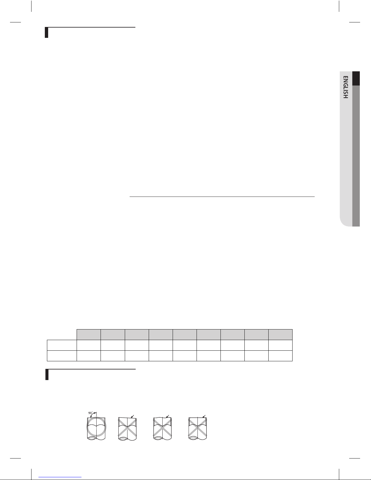
Cutting the pipes
1.
Make sure that you prepared the required tools. (pipe cutter, reamer, flaring tool and pipe holder)
2.
If you want to shorten the pipe, cut it using a pipe cutter ensuring that the cut edge remains at 90°
with the side of the pipe. There are some examples of correctly and incorrectly cut edges below.
Oblique Rough Burr
AM0**JNZDCH/AA IM ENG_V1.5_07082015
12

Performing leak test & insulation
Leak test
LEAK TEST WITH NITROGEN (before opening valves)
In order to detect basic refrigerant leaks, before recreating the vacuum and recirculating the R-410A, it’s responsible of
installer to pressurize the whole system with nitrogen (using a pressure regulator) at a pressure above 595 PSI (4.1MPa).
LEAK TEST WITH R-410A (after opening valves)
Before opening valves, discharge all the nitrogen in the system and create vacuum. After opening valves check
leaks using a leak detector for refrigerant R-410A.
•
Discharge all the nitrogen to create a vacuum and charge the system
CAUTION
Insulation
Once you have checked that there are no leaks in the system, you can insulate the piping and hose.
1.
To avoid condensation problems, place T13.0mm (0.51”) or
thicker Acrylonitrile Butadien Rubber
separately around each
refrigerant pipe.
NOTE
Always make the seam of pipes face upwards.
No gap
NBR [T13.0mm (0.51”) or thicker]
2.
Wind insulating tape around the pipes and drain hose avoiding to
compress the insulation too much.
Indoor unit
Be sure to overlap
the insulation
Insulation pipe
•
Must fit tig
htly against
body without any gap.
CAUTION
3. Finish wrapping insulating tape around the rest of the pipes leading to
the outdoor unit.
4.
The pipes and electrical cables connecting the indoor unit with the
outdoor unit must be fixed to the wall with suitable ducts/straps.
• All refrigerant connection must be accessible, in order to
permit either unit maintenance or removing it completely.
CAUTION
Leak
check
•
You can contact the gas side and liquid side pipes but the pipes
should not be pressed together tightly.
•
When contacting the gas side and liquid side pipe, use 1 grade
thicker insulator.
Gas pipe
Liquid pipe
Insulation
Insulation
AM0**JNZDCH/AA IM ENG_V1.5_07082015
13
 Loading...