

Samsung AM080MXMDGEU, AM080FXMDGH, AM080MXMDGH, AM080FXMDGEU, AM090FXMDGH Installation Manual
...

Contents
AA
Safety precautions ..................................................................... 3
Preparations for Installation .................................................. 6
· Outdoor unit classication ...................................... 6
· Accessories ....................................................................... 6
· Optional accessories ................................................... 7
Selecting installation location .............................................. 7
· Space requirements ................................................. 10
· Moving the outdoor unit ........................................13
Basic construction and installation of the outdoor unit
.......................................................................................................... 14
· Installation of Outdoor unit ................................. 14
Installation of Air-conditioner ........................................... 17
· Refrigerant pipe work .............................................. 17
· Selecting refrigerant pipe ..................................... 18
· Keeping refrigerant pipe ........................................ 21
· Temper grade and minimum thickness of the
refrigerant pipe ........................................................... 21
· Refrigerant pipe welding and safety
information .................................................................... 22
· Cutting or aring the pipes ................................. 23
· Connecting the ared pipes ............................... 24
· Pipe installation for an outdoor unit ............. 25
· Connecting the drain hose to the outdoor unit .
............................................................................................. 26
· Examples of refrigerant pipe installation .... 27
· Allowable length of the refrigerant pipe and
the installation examples ...................................... 28
· Installation of refrigerant Y-joint ....................... 30
· Installation of the distribution header .......... 32
Wiring work ................................................................................ 33
· Specication of the circuit breaker and power
cable ................................................................................. 33
· Specication of the protection tube ............... 34
· Power wiring Diagram ............................................ 35
· Selecting solderless ring terminal .................... 36
· Connecting the power terminal ....................... 36
· Installing grounding wire ..................................... 38
Air tightness test and vacuum drying ........................... 40
· Air Tightness ................................................................ 40
· Vacuum drying pipes and indoor units ....... 41
Charging refrigerant ............................................................. 42
· Important information regulation regarding
the refrigerant used ................................................ 42
· Charging refrigerant .............................................. 43
Pipe insulation ......................................................................... 44
· Insulating the refrigerant pipes and branch
joints ................................................................................. 44
· Selecting the refrigerant pipe insulator ...... 44
· Insulate the refrigerant pipe .............................. 45
· Insulate the distribution header ..................... 46
· Insulating the pipe located inside of the
outdoor unit ................................................................ 47
Basic segment display .......................................................... 48
Setting outdoor unit option switch and key
function ..................................................................................... 49
· Setting outdoor unit key function ................. 49
· Setting key operation and checking the view
mode with tact switch ....................................... 54
Things to check after completing the installation .. 57
Inspection & test operation ................................................59
· Checklist before auto trial operation ............ 59
· Auto trial operation ................................................. 60
Inspection & trial operation ................................................61
Automatic refrigerant amount detection function
..........................................................................................................62
For information on Samsung’s environmental commitments and product specic regulatory obligations
e.g. REACH visit: samsung.com/uk/aboutsamsung/samsungelectronics/corporatecitizenship/data_corner.
html
2
Safety precautions
Please follow the following safety information for safety of the installer and the user.
DVM S ECO air conditioner uses R-410A refrigerant.
• When using R-410A, moisture or foreign substances may affect the performance and reliability of the product.
Safety precautions must be obeyed when installing the refrigerant pipe.
• The designed maximum pressure of the system is 4.1MPa and therefore select appropriate material and thickness
according to the regulations.
• R-410A is a quasi-azeotrope of two refrigerants and it has to be charged in liquid phase when lling the refrigerant.
(If you charge vapor refrigerant, it may change the blend of the refrigerant and cause product malfunction.)
You must connect the indoor units for R-410A refrigerant. Refer to product catalog to nd out the models names
for connectable indoor units. (If you connect the indoor units that are not designed for R-410A, it cannot operated
normally.)
After completing the installation and trial operation, explain to the user how to use and maintain the product. Also,
hand over this installation manual so that it can be stored by the user.
Manufacturer is not responsible for the incidents occurred by improper installation. Installer is responsible for any
installation related claims from the user occurred by neglecting warnings and cautions stated in this manual. (Installer
will be responsible for any service charges that may occur)
Generally, system air conditioners should not be relocated after installation. But when it has to be relocated for
inevitable reasons, please contact Samsung’s qualied dealers for system air conditioners.
ENGLISH
WARNING
CAUTION
• Hazards or unsafe practices that may result in severe personal injury or death.
• Hazards or unsafe practices that may result in minor personal injury (to installer/user) or property
damage.
SEVERE WARNING SIGNS
Consult qualied installer or dealer for installation.
When installation is done by unqualied person, problems such as water leakage, electric shock or re may occur.
Installation work must be done properly according to this installation manual.
When installation is not done properly, it may cause water leakage, electric shock or re.
When installing the unit in a small room, take measure to keep the refrigerant concentration from exceeding allowable
safety limits in case of refrigerant leakage. Consult the dealer for precautionary measure before the installation.
When refrigerant leaks and exceed dangerous concentration level, it may cause suffocation accidents.
If any gas or impurities, except R-410A refrigerant, come into the refrigerant pipe, serious problem may occur and it may
cause injury.
Use the supplied accessories, specied components and tools for the installation.
Do not use the pipe and the installation product used for the R-22 refrigerant.
Failure to use the specied components can cause product fall down, water leakage, electrical shock, and re. (The pipe
and are components used for R-22 refrigerant must not be used)
Install the outdoor unit on a hard and even place that can support its weight.
If the place cannot support its weight, the outdoor unit may fall down and it may cause injury.
3

Safety precautions
AA
Check the following before installation and service work.
Before welding, remove dangerous and inammable things that may cause an explosion and re around the work.
Before welding, remove the refrigerant from inside the pipe or the product.
- If you perform welding while refrigerant is in the pipe, it may increase the pressure of the refrigerant and cause the
pipe to burst. If the pipe bursts or explodes, it may cause severe injury to the installer.
When welding, use the nitrogen gas to eliminate oxidation inside the pipe.
Do not modify the product on your own.
Potential risk of electric shock, re, product failure or injury.
Fix the outdoor unit securely on foundation to resist strong wind or earthquake.
If the outdoor unit is not properly xed, it turns over and accidents may occur.
Electric work must be done by qualied persons, complying the national wiring regulations and installed according to the
instruction stated in the installation manual with leased circuit.
Capacity shortage on the leased circuit and improper installation may cause electric shock or re.
Make sure to perform grounding work.
Do not connect the ground wire to a gas pipe, water pipe, lightning rod or telephone grounding. Improper grounding
could cause electric shock.
Wiring must be connected with the designated wires and it must be xed securely so that it does not apply any external
force to the connection part of the terminals.
If connection for xation is not properly done, it may cause heat generation or re.
Neatly arrange the wires in the electrical parts to make sure that electrical cover is closed securely without any gaps.
If the cover is not properly closed, heat may generate on the electrical terminal and cause electric shock or re.
Exclusive circuit breaker (MCCB, ELB) must be installed to the power supply.
When overcurrent or current leakage occurs with no circuit breaker installed, power will not be cut-off and it may
cause electric shock or re.
Do not use damaged parts. It may cause re or electric shock.
You must cut-off the power before you work on, or adjust any power supply part for product installation, maintenance,
repair or any other services.
There is risk of electric shock.
Even when the power is off, it is dangerous when you come in contact with inverter PCB, fan PCB since high pressure
DC voltage is charged to those parts.
When replacing/repairing the PCB, cut-off the power and wait until the DC voltage is discharged before replacing/
repairing them. (Wait for more than 15 minutes to allow it to discharge naturally.)
If the refrigerant gas leaks during the installation, you should ventilate the room.
When the refrigerant gas gets in contact with ammable substance, it may generate toxic gas.
Gas leakage must be checked after installation is completed.
When the refrigerant gas gets in contact with ammable substance, it may generate toxic gas.
You can get a frostbite if you get in contact with the leaked refrigerant gas.
Supply power to the product during winter time since the product will operate in protection mode itself when the
temperature decrease below 0°C.
If you cut-off the power, compressor protection mode cannot be operated and may cause damage to the product.
The appliance is not intended for use by persons (including children) with reduced physical, sensory or mental
capabilities, or lack of experience and knowledge, unless they have been given supervision or instruction concerning
use of the appliance by a person responsible for their safety: Young children should be supervised to ensure that they
do not play with the appliance.
For use in Europe : This appliance can be used by children aged from 8 years and above and persons with reduced
physical,sensory or mental capabilities or lack of experience and knowledge if they have been given supervision or
instruction concerning use of the appliance in a safe way and understand the hazards involved. Children shall not play
with the appliance. Cleaning and user maintenance shall not be made by children without supervision.
4
CAUTION SIGNS
Do not install the drain pipe directly to the bottom part of the outdoor unit and built a proper drainage so that water drains
out smoothly. If not, pipe may freeze or bursts during winter time and cause damage to the product or water leakage.
When the draining work is not done properly, water leak may occur and cause property damage.
Install the power cable and communication cable of the indoor and outdoor unit at least 1.5m away from the electric
appliances and install it at least 2m away from the lightning conductor.
Noise may be generated from the electronic devices, depending on the status of the electric wave.
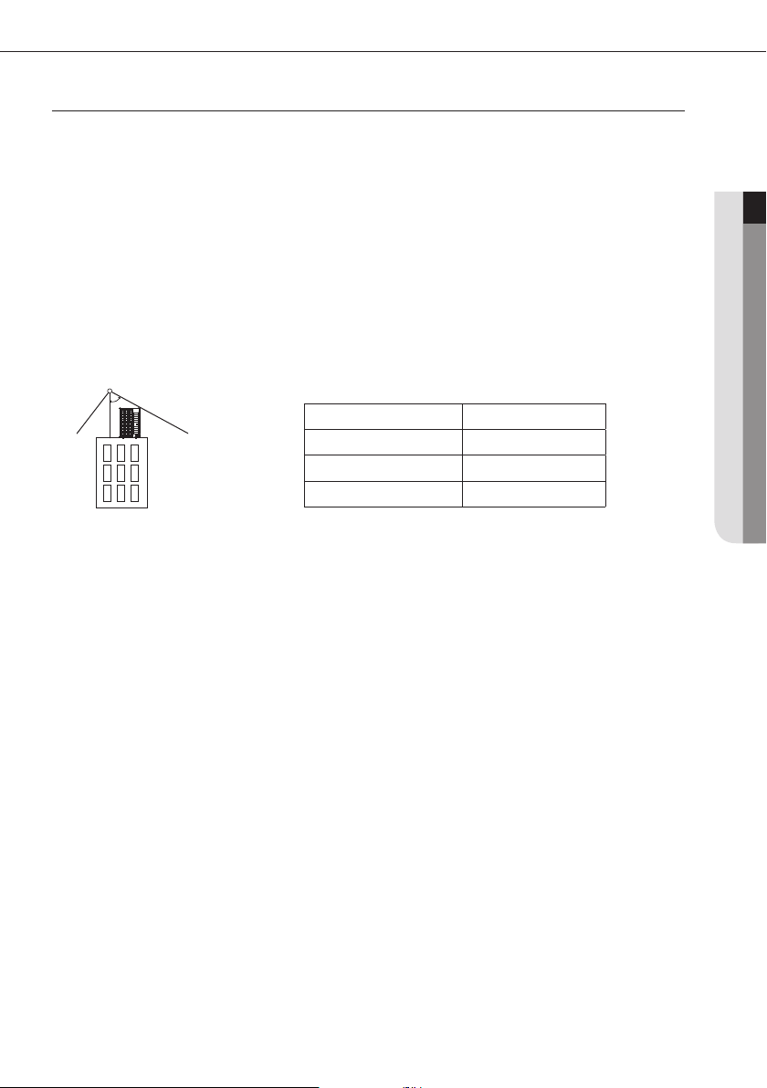
Install the outdoor unit within the angle stated in the table, according to the height of the building.
Do not leave the refrigerant container under the hot sunlight. (There is risk of explosion.)
You must use the appropriate pipes according to the standard since the pressure of the refrigerant is very high.
Make sure that the pipes does not get any weaker by welding it too much.
Make sure to install the product away from children’s’ reach. (Sharp parts of the heat exchanger is may cause personal
injury and when parts of the product gets damage, it may decrease product’s performance.)
Lightning rod
ENGLISH
Protective angle: 25~55°
Building
Install the indoor unit away from lighting apparatus that uses ballast stabilizer.
If you use the wireless remote control, it may not operate normally due to ballast stabilizer.
Do not install the product in following places.
Place where outdoor unit’s noise and warm air may disturb neighbors. (It may cause property loss.)
Do not leave any obstacles around the inlet and outlet of the product. (It may cause damage or accidents.)
The place where there is mineral oil or arsenic acid.
- Those parts may get damaged due to burned resin and cause water leakage or product may fall.
- The efficiency of the heat exchanger may reduce or product may break.
The place where corrosive gas such as sulfurous acid gas generates from the vent pipe or air outlet.
- The copper pipe or connection pipe may corrode and refrigerant may leak.
The place where there is a machine that generates electromagnetic waves.
- The air conditioner may not operate normally due to problems in control system.
The place where there is a danger of combustible gas leakage or place where thinner or gasoline is handled.
- (There is risk of re or explosion.)
The place with carbon ber or ammable dust.
The place near seashore or hot spring where there is risk of outdoor unit corrosion.
Height of the building Protection control
20m or less 55˚
40m or less 35˚
60m or less 25˚
5
Safety precautions
AA
Changes in DVM S ECO (inverter) compare to conventional models that has to noted when installing
For optimal distribution of the refrigerant, you must use Y-joint as branch joint for connecting outdoor units. (To not use
T-joint)
You cannot operate normally if you do not complete the trial operation through outdoor unit key mode. You must use
KEY MODE to run trial operation.
DVM S ECO air conditioner uses R-410A refrigerant.
Check the compatibility of other products such as indoor unit, EEV kits etc. which will be connected to DVM S ECO.
Preparations for Installation
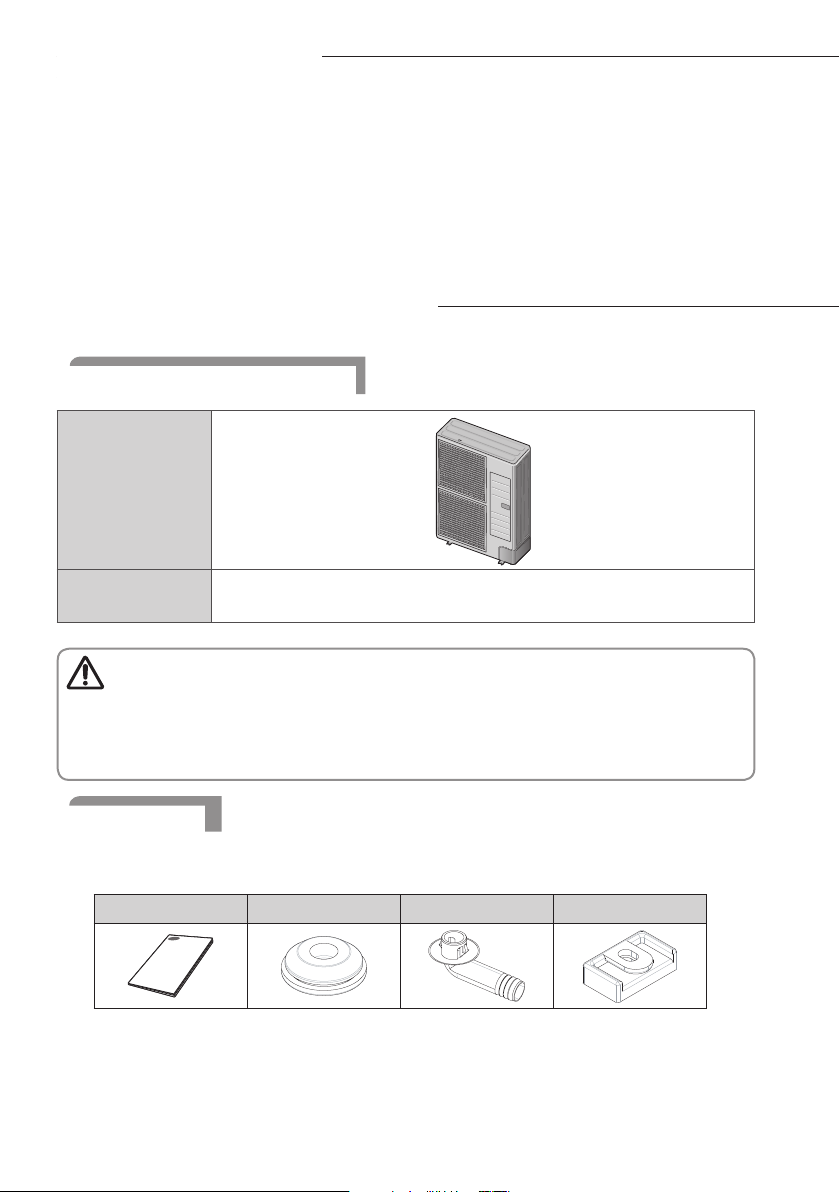
Outdoor unit classication
Appearance
DVM S ECO
Packaging material disposition
• Safely store or dispose the packaging materials.
Caution
- Sharp metals such as nails or wooden material packaging that may break into pieces become a cause for
personal injury.
- Make sure to store or dispose the vinyl type packaging material to keep it out of reach of children. Children
may put them over their face, which is very dangerous since it may lead them to suffocation.
AM080/090FXMDG
AM080MXMDG
Accessories
You must keep following accessories until the installation is nished.
Hand over the installation manual to the customer after nishing the installation.
Installation Manual(1) Cap Drain(3) Drain Plug(1) Rubber Leg(4)
6
Preparations for Installation
AA
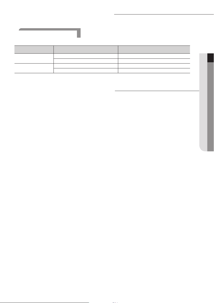
Optional accessories
The following accessories are needed when connecting the outdoor and indoor unit.
Model Model Total capacity
Y-joint
Distribution header
Refrigerant distributor component has to be installed when connecting indoor unit with no built-in EEV (electronic
expansion valve)
MXJ-YA1509M 15.0 kW and below
MXJ-YA2512M Over 15.0 kW ~ 40.0 kW and below
MXJ-HA2512M 45.0 kW and Below (for 4 rooms)
MXJ-HA3115M 70.3 kW and below (for 8 rooms)
Selecting installation location
Decide the installation location, with the consideration of the following conditions, under user’s approval.
Place where hot discharge air or noise from the outdoor unit may not disturb the neighbor (Especially in residential
areas, keep the operation hours in mind.)
Place where structure can bear the weight and vibration of the outdoor unit.
Place with at surface where rainwater does not settle or leak.
Place where it is not exposed to strong wind.
Well ventilated place with sufficient service place for repairs and maintenance. (Discharge duct can be purchased
separately)
Place where you can connect the refrigerant pipes between indoor and outdoor units within allowable distance.
Place where it allows easy waterproong and draining work for the condensation water generated from the outdoor
unit during heating operation.
Place where there is no risk of inammable gas leakage.
Place where there is no direct inuence of snow or rain.
Do not install the product in a place where it will be directly exposed to sea breeze.
- Consult an installation expert (or company) since you will need to take extra anti-corrosion measures if you need to
install the product in a place where it can be exposed to direct sea breeze. (You have to remove dusts and salinity on
the heat exchanger and apply designated rust inhibitor more than once a year.)
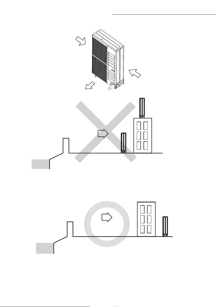
If the outdoor unit is installed in the location where it can be attacked by high wind, please pay attention to these
issues:
- Caution when outdoor unit air outlet side was blow by high wind that speed over 5m/s, Because the outlet air was
suctioned in once again, reduce the airow of machine, and may cause these appearance:
- Lower capacity; -severe frost in heating mode; - machine break down for high pressure .
If the air outlet side of the outdoor unit encountered a large continuous strong wind blowing, the fan will run reversely
with high speed, and may be damaged by it. so please refer to the installation instruction.
ENGLISH
7
Selecting installation location
AA
Strong breeze
Exhaust
Strong breeze
Outdoor unit
Sea breeze
Sea
Caution when installing the product in seashore
- When installing the product in seashore, make sure to install it behind a structure (such as building) that can block the
sea breeze or install protection wall around the outdoor unit.
- Make sure to install the product in a place where it allows smooth drainage.
Sea breeze
Sea
Outdoor unit
Outdoor unit
8
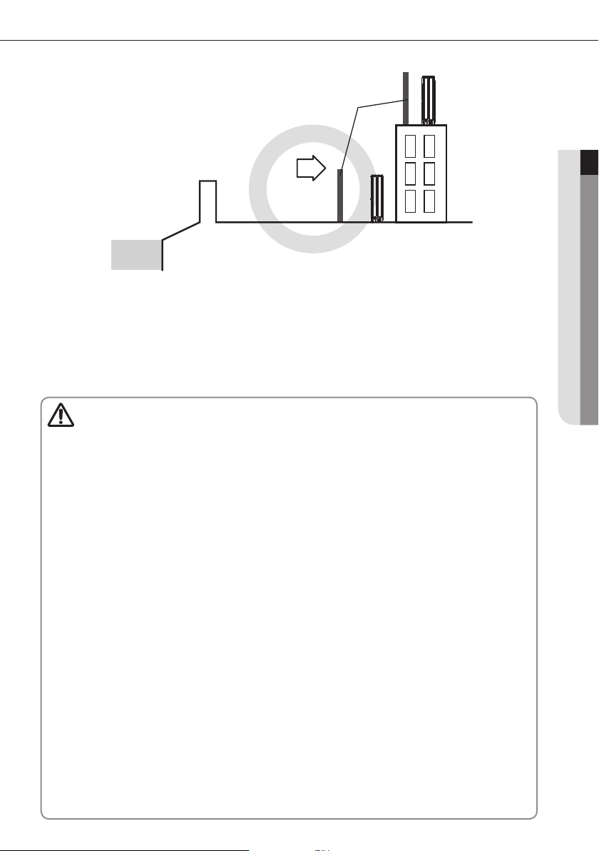
Protection wall
Outdoor unit
Sea breeze
Sea
Protection wall should be constructed with a solid material that can block the sea breeze and the
height and width of the wall should be 1.5 times larger than the size of the outdoor unit. (You
must secure more than 700mm of space between the protection wall and the outdoor unit for air
circulation.)
Choose a place free of direct sunlight.
Choose a place free of exposure to the rain and snow.
Choose a place free of leakage of inammable gases.
Choose a place that the pipelines are accessible to the indoor and outdoor unit.
System air conditioner may cause static noise when listening to AM stations. Therefore, select an installation
Caution
location for indoor unit where electrical wiring can be done while keeping certain distance from a radio,
computer and stereo equipment.
Especially, keep the unit at least 3m away from the electrical equipment in an area with weak
electromagnetic waves and put the main power cable and communication cables in a separately installed
protection tube.
Make sure that there is no equipment that generates electromagnetic waves. If not electromagnetic waves
may cause problem to the control systems which may lead to air conditioner malfunction. (Example:
Remote control sensor of the indoor unit may not receive the signal very well, due to ballast stabilizer of the
lighting equipment.)
In regions with heavy snowfall, make sure to install the outdoor unit where there is no concerns of direct
snowfall on the outdoor unit. Also, build higher base support so that accumulated snow does not block the
air inlet or the heat exchanger.
R-410A refrigerant is a safe, nontoxic and nonflammable refrigerant. However, if the place holds any
concerns for exceeding dangerous level of refrigerant concentration in case of refrigerant leakage, extra
ventilation system is required.
When you install the outdoor unit in a high places such as roof, install fence or guardrail around it. When
there is no fence or guardrail, service person could fall.
Do not install the product in places where corrosive gases such as sulfur oxides, ammonia, and sulfurous gas
are produced. (e.g. Toilet outlet, ventilation opening, sewage works, dyeing complex, cattle shed, sulfuric hot
spring, nuclear power plant, ship etc.) When installing the product in those places, contact an installation
specialty store as the copper pipe and brazing part will need additional corrosion proof or anti-rust additive
to prevent corrosion.
Make sure to keep any inammable materials (such as wooden materials, oil etc.) around the outdoor unit.
When there's re, those inammable material will easily catch the re and may pass it on to the product.
Depending on the condition of power supply, unstable power or voltage any cause malfunction of the parts
or control system. (At the ship or places using power supply from electric generator...etc)
When the outdoor unit is installed near seashore or in a place where sulfuric acid gas may leak, corrosion
may occur in outdoor unit and cause product malfunction.
Outdoor unit
ENGLISH
9
Selecting installation location
AA
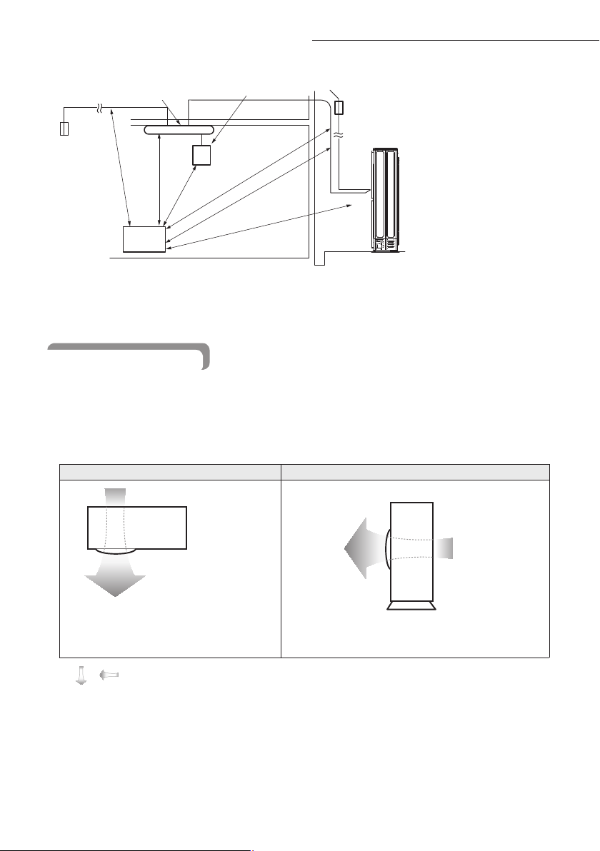
Indoor unit
Breaker
1.5m or more
1m or more
1m or above
Stereo
Make sure that the water dripping from the drain hose runs away correctly and safety.
You should repaint or protect the damaged part so that the paint of the cabinet does not peel off and become rusty during
installation.When the cabinet becomes rusty,the life of an outdoor will be reduced.
Remote control
1.5m or more
1.5m or more
3m or more
Breaker
Outdoor unit
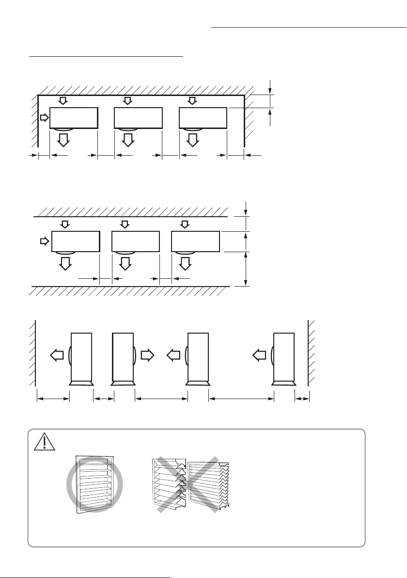
Space requirements
Make a space for ventilation and service as seen in the picture.
When multiple outdoor units are combined for installation,allow enough space for ventilation against a wall.If the
ventilation space is not allowed,product malfunction may occur.
The side with logo is the front side of the outdoor unit.
Figure description
Top view Side view
Back side : Air intake
10
•
Direction of airow
\
Front side : Air outlet
Front side:
Air outlet
Back side : Air
intake
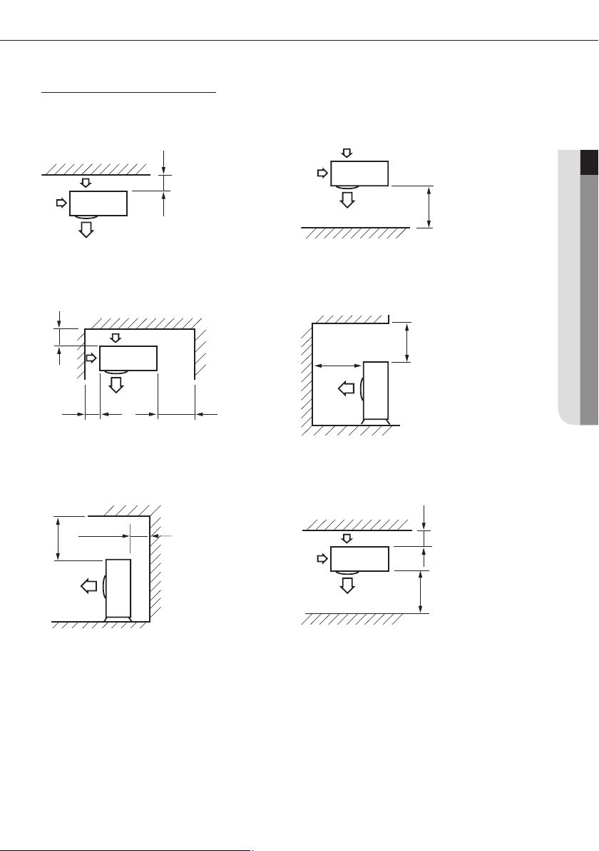
When installing an outdoor unit
When the air outlet is opposite the wall
When the air outlet is toward the wall
Unit: mm
ENGLISH
300 or more
When 3 sides of the outdoor unit are blocked by the wall
300 or more
150 or more
The upper part of the outdoor unit is blocked and the air
outlet is opposite the wall
300 or more
500 or more
600 or more
1500 or more
The upper part of the outdoor unit is blocked and the
air outlet is toward the wall
2000 or more
1500 or more
When the walls are blocking front and the rear of the
outdoor unit
1500 or more 300 or more
11
Selecting installation location
AA
When installing more than 1 outdoor unit
When 3 sides of the outdoor unit are blocked by the wall
300 or more 600 or more 600 or more 600 or more
When the walls are blocking front and the rear of the outdoor units
600 or more 600 or more
When front and rear side of the outdoor unit is toward the wall
Unit: mm
300 or more
300 or more1500 or more
1500 or more 600 or more 3000 or more 3000 or more3000 or more
• Should adopt bar type louver. Don’t use a type of rain resistance louver.
Warning
[Bar type louver] [Rain resistance louver]
• Louver specications.
- Angle criteria : less than 20˚
- Opening ratio criteria : greater than 80%
12
Moving the outdoor unit
Select the moving path in advance.
Be sure that moving path can support weight of the outdoor unit.
Do not slant the product more than 30˚ when carrying it. (Do not lay the product down in sideways.)
Surface of the heat exchanger is sharp. Be careful not to get injured while moving the product.
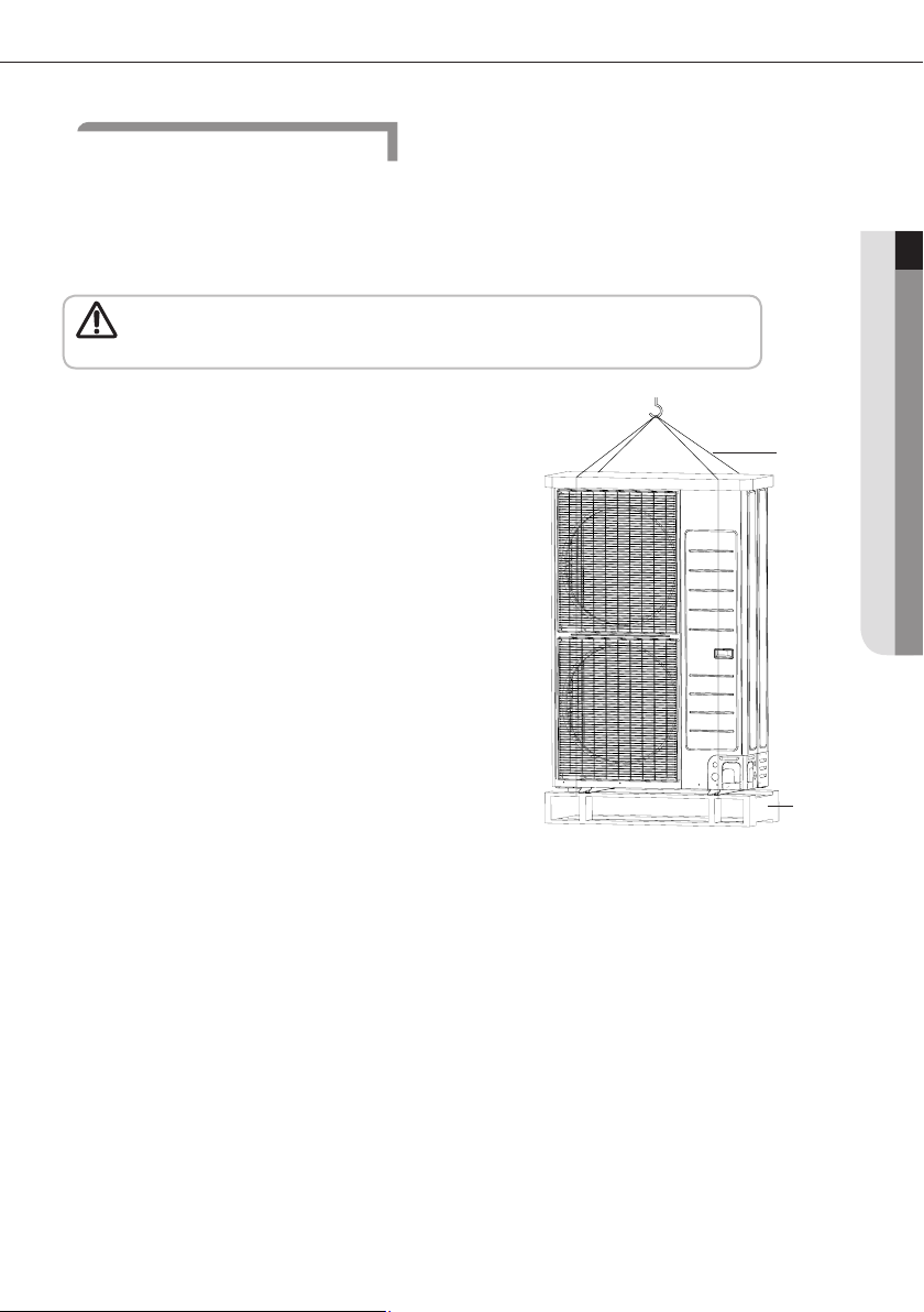
• You must use certain part of the product when moving the product.
Caution
1)When moving with a crane
Fasten the wire rope as shown in the gure.
To protect damage or scratches, insert a piece of cloth between the
outdoor unit and the wire rope.
2) When moving with a forklift
Carefully insert the forklift forks into the forklift holes at the bottom
of the outdoor unit.
Be careful with the forklift from damaging the product.
3) When moving the product without wooden pallet and the crane
is not available for use
Connect a wire rope to the outdoor unit as you would move it with a
crane.
Hang the wire rope to the forklift fork to move the outdoor unit.
ENGLISH
Wire rope
Wooden pallet
13
Base construction and installation of the outdoor unit
AA
Installation of outdoor unit
Make sure to remove the wooden pallet before installing the outdoor unit. If you do not remove the wooden
pallet, there is risk of re during welding the pipes. If the outdoor unit is installed with wooden pallet on,
Warning
1. Install the outdoor unit 150mm higher than the base ground and install the drain hole to connect the pipe to the
2. When the front fan of an outdoor unit is installed in a place where the average snowfall is more than 150mm, the
3. The concrete foundation should be 1.5 times larger than bottom of the outdoor unit.
4. It is necessary to install wire mesh or steel bar when outdoor units are installed on a soft foundation.
5. When installing multiple outdoor units at the same place, install the H beam on the base ground. (When installing a
6. Install the H beam(150mm x 150mm x t10 : basic specication) or vibration absorption frame to jut out from the base
7. After installing the H beam, apply corrosion protection.
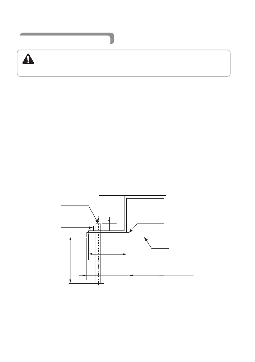
8. Install a square pad(t=20mm or more) to prevent vibration from the outdoor unit onto the base ground. Place the
and it was used for long period time, wooden palette may break and cause electrical hazard or high pressure
may damage the pipes.
drainage.
discharge duct should be attached to the outdoor unit.
number of outdoor units, you can install it on the base ground.)
ground.
outdoor unit on the H beam and x it with the bolt, nut and washer. (Fix with M10 basic anchor bolt, nut and washer.)
Unit: mm
Outdoor unit
14
Anchor bolt
Nut, Spring wahser
75mm or
more
20mm
Square pad
H-beam
A
A+10~20mm or more
Base ground contruction
Drain hole
150 mm or more
(when Installing on the ground)
Install the outdoor unit
horizontally on the ground
(when Installing on the roof)
150 mm or more
The outdoor unit should be supported within the range of measurement below for base ground work.
Unit: mm
Anchor bolt position
330
360
384
620
940
When the outdoor unit needs to be supported,x it with wire as shown in the picture.
- Slightly unwind the four screws on the cover top of the outdoor unit.
- Wind wires round the four screws and fasten the screws again.
- Fix the wires to the ground.
ENGLISH
• If the outdoor unit is not xed securely,product may fall and it might cause loss of life or property damage.
• Do not install the outdoor unit on the wooden pallet.
Caution
• Fix the outdoor unit securely to the base ground with anchor bolts.
• The manufacturer is not responsible for the damage occurred by not adhering to the standard of the
installation.
• To protect the outdoor unit from external condition such as rain, install it on the base ground and connect
the drain pipe to the drainage.
15
Base construction and installation of the outdoor unit
AA
• Please rstly ensure the strength and levelness of the platform, ground and the support so as to lower the
noise and vibration for fear of human injuries.
Caution
• The hanging mount on the wall is not recommended due to the heavy machine.
• If the hanging mount on the wall is required, please entrust the distributor to do so and strictly following
the following requirements. The improper installation shall lead to the fall of the machine as well as human
injuries.
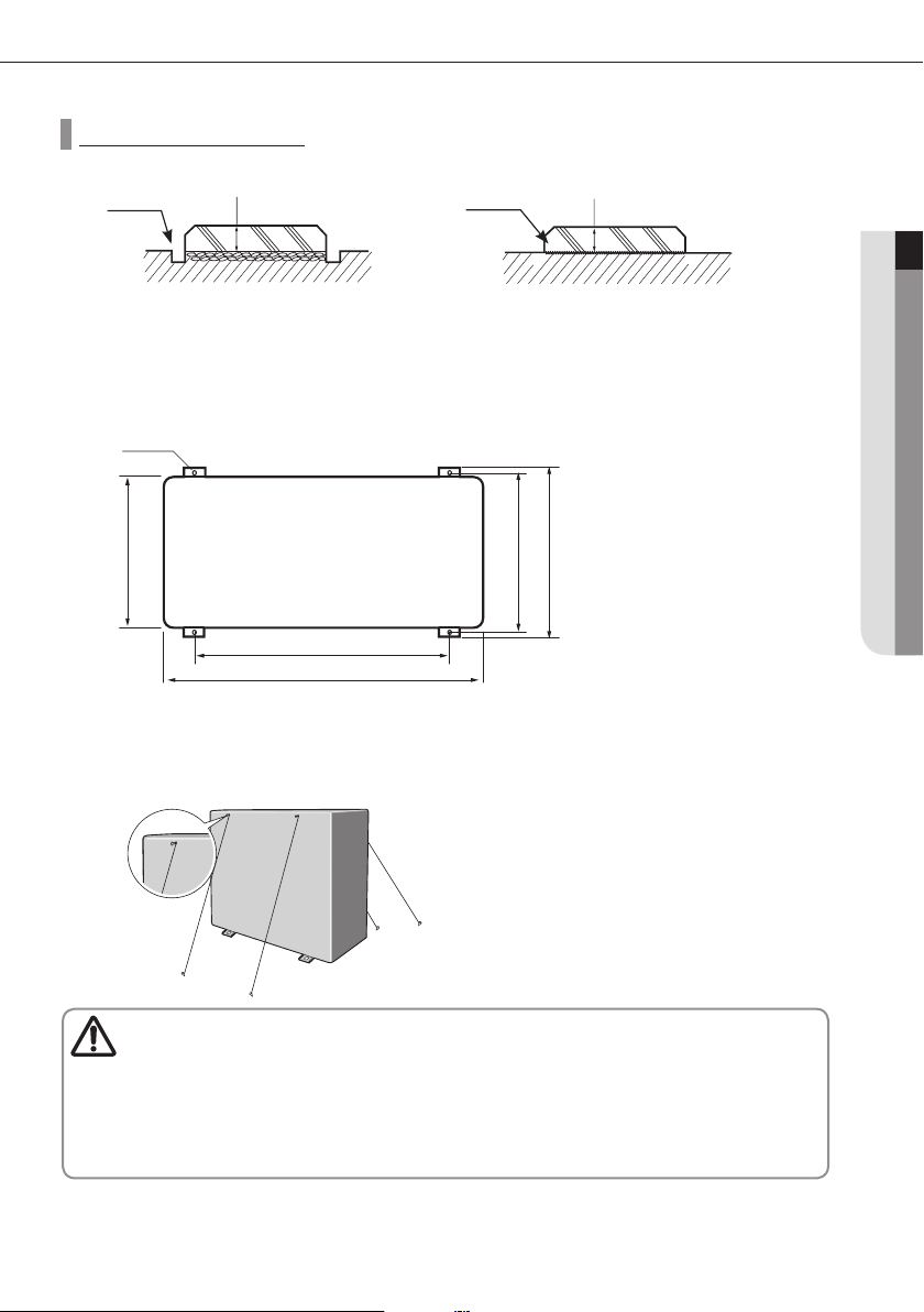
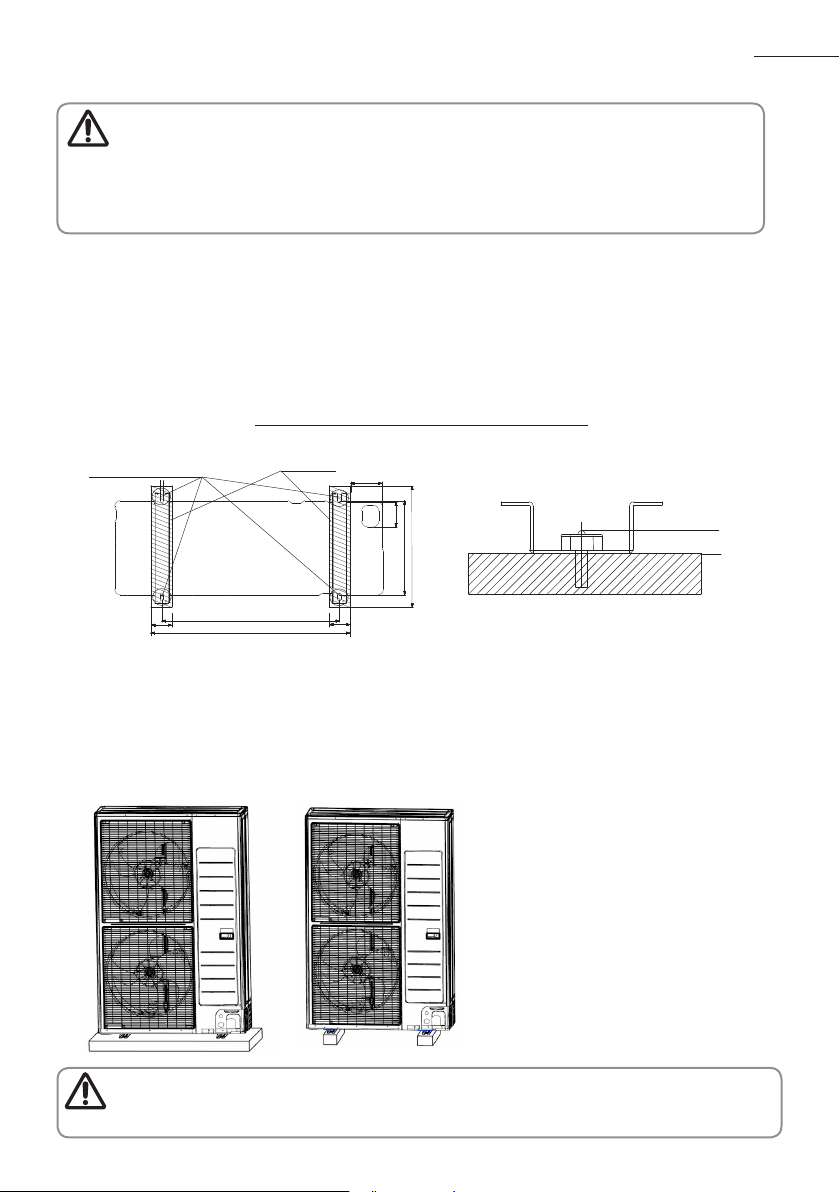
<The machine shall be installed on the ground or on the high platform>
As shown in Figure 1, to ensure the shadow part is on the bearing surface without suspension.
As shown in Figure 1, the four installation footings shall be rmly fastened on the base platform by the bolts (preparing
four sets of M12 bolts with tful nuts and washer which are used on site)
In order to reduce the vibration of the noisemeter, the vibration absorber (offer on site) shall be used between the
contact of machine and base platform.
It is optimal that anchor bolt is 20mm above the surface. (See Figure 2)
The base of the outdoor unit and the position of foundation bolts
Position of the foundation bolts
(Ø12.0 Hole 4Points)
↔
Bearing surface
>100
Unit: mm
86
328
410
↕
20mm
>90
Please ensure the shadow part in Figure 1 is really installed on the bearing surface without any suspension.
he ground base that is larger than the standing leg of the air-conditioner (90mm in width and 410mm in length) shall
620
695
Figure 1
>90
Ground plan
Figure 2
be used to support the air-conditioner (See Figure 1), and the rubber mat shall be fully placed on the whole bearing
surface.
The base platform shall be at least 150mm above the ground.
• When the grounding pipe comes out from the below, please reserve the place for the connection pipe.
• The installation mode mentioned above shall ensure that the shadow part in Figure 1 is really on the installation
Caution
surface.
16
Installation of Air-conditioner
AA
• When installing, make sure there is no leakage. When collecting the refrigerant, stop the compressor rst
Warning
before removing the connection pipe. If the refrigerant pipe is not properly connected and the compressor
works with the service valve open, the pipe inhales the air and it makes the pressure inside of the
refrigerant cycle abnormally high which may lead to explosion and injury.
Refrigerant pipe work
The length of refrigerant pipe should be as short as possible and the height difference between an indoor and outdoor
unit should be minimized.
Piping work must be done within allowable piping length, height difference, and the allowable length after branching.
The pressure of the R-410A is high. Use only certied refrigerant pipe and follow the installation method.
After installing the pipes, calculate the total length of the pipe to check if additional refrigerant is needed. When you
need to charge the additional refrigerant, make sure to use R-410A refrigerant.
Use clean refrigerant pipe and there shouldn’t be any harmful ion, oxide, dust, iron content or moisture inside pipe.
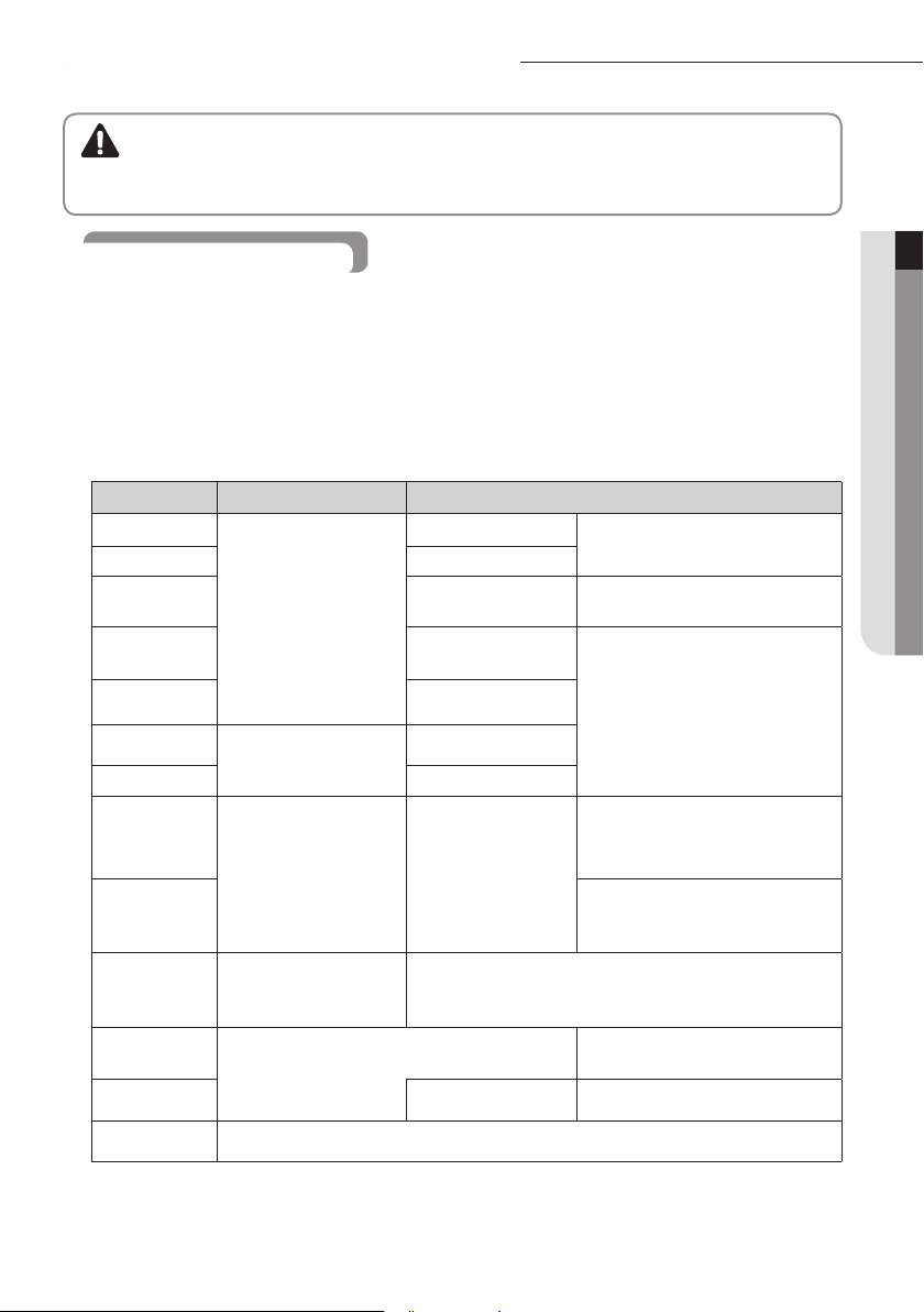
Use tools and accessories that t on R-410A only.
Tools
Pipe cutter
Flaring tool Pipe aring
Refrigerant
machine oil
Torque wrench
Installation process/purpose Compatibility with conventional tool
Pipe cutting
Refrigerant pipe installation
Apply refrigerant oil on
ared part
Connect are nut with
pipe
Exclusive ether oil, ester oil, alkali
benzene oil or synthetic oil
Compatible
ENGLISH
Pipe bender Pipe bending
Nitrogen gas
Welder Pipe welding
Manifold gage
Refrigerant
charging hose
Vacuum pump
Electronic scale for
refrigerant filling
Air leak tester
Pipeline joint
Air tightness test
Air tightness test ~ additional
refrigerant charging
Pipe drying
Must use the are nut equipped with the product. Refrigerant leakage may occur
Prevent oxidation within
the pipe
Vacuumizing, refrigerant
filling as well as inspecting
operation
Compatible (Use products which contain the check valve to prevent
the oil from owing backward into the outdoor unit.) Use the one
Gas leak test
when the conventional are nut for R-22 is used.
Compatible
Need exclusive one to prevent mixture
of R-22 refrigerant oil use and also the
measurement is not available due to
high pressure
Need exclusive one since there is risk of
refrigerant leakage or inow of impurities
that can be vacuumed up to -100.7kpa(5Torr).
Compatible
Need exclusive one
(Ones used for R-134a is compatible)
17
Installation of Air-conditioner
AA
Selecting refrigerant pipe
Install the refrigerant pipe according to main pipe size of each outdoor unit capacity.
When the pipe length (including elbow) between an outdoor unit and the farthest indoor unit exceeds 90m, you
must increase the size of the gas pipe (main pipe) by one grade which connects between the outdoor unit to the rst
branch joint. (The liquid pipe size will be maintained.)
If the capacity of the outdoor unit can decline due to the pipe length, upgrade the pipe size one step (gas pipe).
First branch joint
Increase the main pipe size
Size of the between the outdoor unit and the rst branch joint
Outdoor unit capacity [HP] Liquid pipe [mm] Gas pipe [mm] Increased gas pipe [mm]
8
9
Ø
9.52
Ø
9.52
Ø
Ø
19.05
19.05
Ø
Ø
22.23
22.23
Selection of branch joint
Selection of the rst branch joint
Outdoor unit capacity
[HP]
8 MXJ-YA2512M
9
Model name
MXJ-YA2512M Over 15.0 kW ~ 40.0 kW and below MXJ-YA2512M
Selection of the other branch joint according to the sum of indoor unit capacity which
will be connected after the branch
Classication
Y-joint
Distribution
Header
Indoor unit capacity
[kW]
15.0 kW and below MXJ-YA1509M
45.0 kW and Below (for 4 rooms) MXJ-HA2512M
70.3 kW and below (for 8 rooms) MXJ-HA3115M
Size of the pipe between branch joints
Selecte the pipe size according to the sum of indoor unit capacity which will be connected after the branch.
Inddor unit capacity
[kW]
15.0 kW and below
Over 15.0 kW ~ 22.4 kW and below
Over 22.4 kW
18
Liquid pipe
[mm]
Ø
9.52
Gas pipe
[mm]
Ø
15.88
Ø
19.05
Ø
22.23
Model name
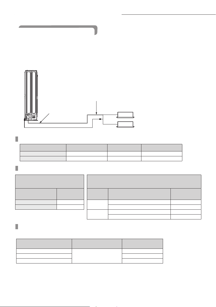
Selecting additional refrigerant charging
Basic refrigerant
The basic amount of refrigerant charged at a factory
Outdoor unit (Series) Factory charge (kg) Connect maximum number of indoor (unit)
AM080XMDG
AM090FXMDG
Amount of additional refrigerant depending on the pipe size.
Amount of additional refrigerant depending on the pipe size (kg) = {(L1 x 0.02) + (L2 x 0.06)}
L1: Total length of the liquid pipe Ø6.35 (m)
L2: Total length of the liquid pipe Ø9.52 (m)
In case of using EEV kit, amount of additional refrigerant of liquid pipe between EEV kit and indoor unts is 0.01kg per
meter
3.7 13
3.7 14
ENGLISH
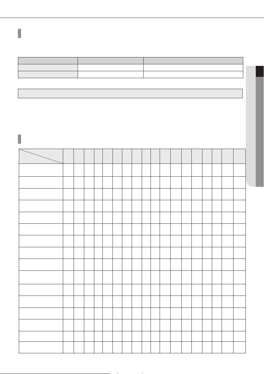
Amount of additional refrigerant for each indoor unit
Capacity (KW )
Model
Slim 1way cassette(JSF)
(AMFN1DEH)
2way cassette
(AMFN2DEH)
Global 4way cassette
(AMFN4DEH)
Floor Standing Unit
(AMFNFDEH)
ERV plus
(AMFNKDEH)
Global mini 4way cassette
(AMFNNDEH)
Slim duct
(AMFNLDEH)
MSP duct
(AMFNMDEH)
Ceiling
(AMFNCDEH)
Console
(AMFNJDEH)
Neo forte
(AMFNTDEH)
Neo forte(with EEV )
(AMFNQDEH)
HSP Duct
(AMFNLHDEH)
Home Duct
(AMKNLDEH)
MAX4
(AMMNQDEH)
HOME DUCT 1&2
(AMMNLDEH)
1.5 1.7 2.2 2.8 3.6 4.5 5.6 6.0 7.1 9.0 9.3 11. 2 12.8 14.0 22.0 28.0
0.25 0.25 0.25
0.31 0.47
0.45 0.45 0.45 0.45 0.57 0.69 0.69
0.22 0.32 0.32
0.29 0.29 0.29 0.29 0.37 0.37 0.37
0.17 0.17 0.17 0.26 0.35 0.35 0.45 0.42 0.42 0.62 0.62
0.24 0.24 0.24 0.28 0.28 0.28 0.32 0.54 0.68 0.68
0.39 0.39
0.27 0.27 0.27
0.24 0.24 0.24 0.24 0.36 0.36
0.24 0.24 0.24 0.24 0.36 0.36 0.36
0.68 0.68 0.68 1.18 1.18
0.13 0.13 0.13 0 .17
0.68
0.24 0.24 0.31
If AHU kit is included among the indoor units,you must add 0.063kg of refrigerant for every 1kW of the AHU capacity increase.
500
CMH
0.11 0.36
Unit: kg
1000
CMH
19
Installation of Air-conditioner
6Ø.53
m01
AA
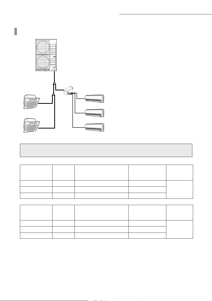
Method to calculate total amount of additional refrigerant
m01 * 25.9Ø
*
m5 * 25.9Ø
*HEDTNF630MA*HED4NF170MA
m5 * 25.9Ø
*HED4NF540MA
m01 * 53.6Ø
m5 * 53.6Ø
*HEDTNF630MA
m5 * 53.6Ø
*HEDTNF630MA
m5 * 53.6Ø
Total amount of additional refrigerant
Total amount of additional refrigerant = Amount of additional refrigerant depending on the pipe length
+ Amount of additional refrigerant for each indoor unit
Amout of additional refrigerant depending on the pipe length
Size of Liquid pipe
(mm)
Ø6.35
Ø9.52
Length(m)
20 0.02 0.4
20 0.06 1.2
Unit amount of refrigerant
(kg/m)
Amount of additional
refrigerant (kg)
EEV kit ~ indoor unit 15 0.01 0.15
Amount of additional refrigerant charging for each indoor unit
Model name of
Indoor unit
AM045FN4DEH*
AM071FN4DEH*
Number of
units (EA)
1 0.45 0.45
1 0.45 0.45
Unit amount of refrigerant
(kg/m)
Amount of additional
refrigerant (kg)
AM036FNTDEH* 3 0.24 0.72
Total amount of additional refrigerant = 1.75 + 1.62 = 3.37 (kg)
Total amount
of additional
refrigerant (kg)
1.75
Total amount
of additional
refrigerant (kg)
1.62
20
 Loading...