

Samsung AM036NXMDCR, AM048NXMDCR, AM053NXMDCR, AM060NXMDCR Service Manual
Refer to the service manual in the GSPN(see the rear cover) for the more information.
AIR CONDITIONER CONTENTS
SYSTEM AIR CONDITIONER
OUTDOOR UNIT
AM036NXMDCR
AM048NXMDCR
AM053NXMDCR
AM060NXMDCR
■ Product Specifications
■ Disassembly and Reassembly
■ Refrigerant pipe installation
■ Troubleshooting
■ PCB Diagram
■ Wiring Diagram
■ Reference Sheet
■ Check Operation & Amount of
Refregent Automatically Checking

Contents
■ Product Specifications .......................................................................................... 4
1. The Feature of Product .................................................................................................................................. 4
1-1 Feature ............................................................................................................................................................................ 4
2. Product Specifications .................................................................................................................................10
■ Disassembly and Reassembly ............................................................................12
■ Refrigerant pipe installation .............................................................................. 32
1. Examples of the correct refrigerant pipe installation for Heat Recovery ................................32
2. Examples of the incorrect refrigerant pipe installation for Heat Recovery ............................33
■ Troubleshooting .................................................................................................. 34
1. Error Display .....................................................................................................................................................34
2. Error Code .........................................................................................................................................................35
3. How to take measures for each symptom ...........................................................................................38
3-1 Communication error between indoor and
outdoor units during tracking (Error Code : E201).................................................................................38
3-2 Communication error between indoor and
outdoor units after completing tracking (Error Code : E202) ...........................................................39
3-3 Communication error (1 minute) between Main and
Sub Micoms of an Outdoor unit or among Outdoor Units (Error Code : E203) .......................40
3-4 MCU branch part setup error
– inconsecutive connection with the use of 2 branch parts .............................................................41
3-5 MCU branch part setup error
– Repeated setup for the same address over 3 times ..........................................................................42
3-6 MCU branch part setup error
– non-installed address setup .........................................................................................................................43
3-7 Communication error (1 minute) between Main and
Sub Micoms of an Outdoor unit or among Outdoor Units (Error Code : E203) ...................................44
3-8 MCU branch part setup error
– Overlapping Indoor unit Address setup .................................................................................................45
3-9 MCU branch part setup error
– Set as being used without connection to an Indoor unit ..............................................................46
3-10 MCU branch part setup error
– Connect an Indoor unit to a branch part not being used ..............................................................47
3-11
MCU branch part setup error
– Connect more Indoor units than what is actually set up in MCU ............................................................48
3-12 MCU/MCU subcooler entrance/exit sensor error (Open/Short) ......................................................49
3-13 Outdoor temperature sensor error(Open/Short)
(Error Code : E221, E231, E251, E269, E276, E311 E321, E322, E323) ..............................................50
3-14 High pressure temperature sensor error (Open/Short) (Error Code : E291)
Low pressure temperature sensor error (Open/Short) (Error Code : E296) ................................51
3-15 Compressor down by antifreeze control (Error Code: E403) .............................................................52
3-16 Comp. down due to a protective control of high pressure (Error Code : E407) ........................53
3-17 Comp. down due to a protective control of low pressure (Error Code : E410) ..........................54
3-18 Comp. down due to a discharge
temperature sensor of a compressor (Error Code : E416) ..................................................................55
3-19 Reverse phase detection error (3Phase outdoor unit) (Error Code : E425) .................................56
3-20 ESC EEV open error (Error Code : E438)........................................................................................................57
3-21 Refrigerant leakage error (Error Code : E439)............................................................................................58
3-22 Prohibition of the compressor operation due to outdoor temperature
(Error Code : E440, 441) ......................................................................................................................................59
3-23 Refrigerant leakage error (during operation) (Error Code : E443) ...................................................59
3-24 Outdoor unit fan error (Error Code : E458, 475 ) ......................................................................................60

3-25 Comp down due to OLP temperature control (Error Code : E463) .................................................61
3-26 Compressor starting/rotation error (Error Code : E461, E467) ..........................................................62
3-27 Current error / PFC overload error (Error Code : E462, E484) .............................................................64
3-28 IPM over current error (Error Code : E464) ..................................................................................................65
3-29 DC-Link voltage under/over error (Error Code : E466) ..........................................................................68
3-30 Others ..........................................................................................................................................................................70
■ PCB Diagram ........................................................................................................71
1. Outdoor Unit PCB ..........................................................................................................................................71
■ Wiring Diagram .................................................................................................... 75
1. 1 Phase (AM036/048/053/060NXMDCR) ..............................................................................................75
■ Reference Sheet ................................................................................................... 76
1. Refrigerant cycle diagram ..........................................................................................................................76
1-1 AM036/048/053NXMDCR ....................................................................................................................................76
1-2 AM036/048/053NXMDCR (Cooling mode) ..................................................................................................77
1-3 AM036/048/053NXMDCR (Main cooling mode) .......................................................................................78
1-4 AM036/048/053NXMDCR (Heating mode) ..................................................................................................79
1-5 AM036/048/053NXMDCR (Main heating mode) .......................................................................................80
2. Nomenclatures ...............................................................................................................................................81
2-1 OUTDOOR UNIT ........................................................................................................................................................81
■ Check Operation & Amount of Refrigerant Automatically Checking ............ 82
1. Check Operation ...........................................................................................................................................82
1-1 Check Operation ......................................................................................................................................................82
1-2 How to troubleshoot of the "Undetermined" .............................................................................................84
1-3 Automatic Commissioning Error Code ..........................................................................................................90
2.
Automatic refrigerant amount detection function (Checking th amount of refrigerant)
.............91
4
Samsung Electronics
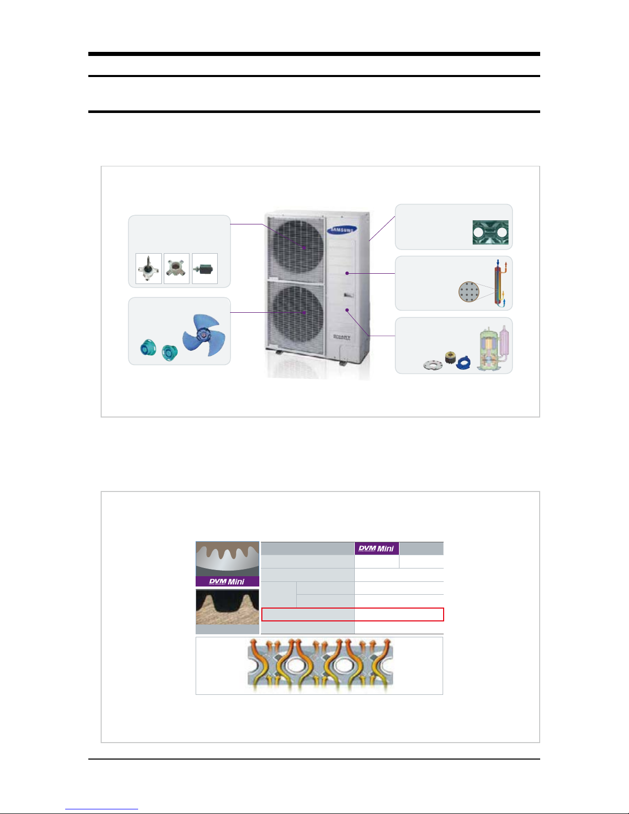
High performance BLDC fan motor
Cross section of a Turbo Inter-cooler
33% more ecient compare to AC motor
Wide speed control range, less noise
generation
Turbo Inter-cooler
Long piping up to 175m with sub-cooling
Up to 50m levela dierence is allowed for
installation
Twin BLDC compressor
Increased energy eciency
compare to conventional compressor
Stable operation with 80%
decreased vibration
Anti-chloride coated outdoor unit
heat exchanger
Anti-corrosion /erosion G-Fin
provide stable heat exchanging
performanceation
High ecient propeller fan
Reduced noise on outdoor
unit
Improved heat exchange
rate
Company A
Company A
Diameter
Ø8 Ø7
Heat transfer surface area
19%
Evaporation
14.1%
Condensation
10.3%
Internal heat transfer performance
30.8%
Pressure resistance
Same
➜➜
➜
Pressure
loss in heat
exchanger
■ Product Specifications
1. The Feature of Product
1-1 Feature
High efficient heat exchanger
High efficient G-Fin & epoxy acrylic coating has increased heat transfer and hydrophilicity on heat exchanger.
Structure of outdoor unit

Product Specifications
Samsung Electronics
5
20 30 40
0
2
4
8
10
12
0.00
0.08
0.04
0.12
0.24
0.16
Amount of transferred heat (kW/m)
Refrigerant ow (Kg/h)
Increased by 30.8%
Decreased by 14%
Pressure loss (kPa/m)
Ø7 Groove Ø8 High Groove
New Ø7 wide n
Ø7 wide n
Heat transfer
amount
15%
New Ø8 wide n
Ø8 Fin
Heat transfer
amount
15%
Feature (cont.)
Optimized cooling/heating and increased system efficiency! Liquid EEV & Turbo Inter-cooler
• Liquid EEV for increased efficiency of the system
Through Liquid EEV, controlling of valve opening has become more efficient and it achieved optimized system efficssiency and
minimized noise from the refrigerant in the indoor unit.
• Turbo Inter-cooler
High performing shell & tube type heat exchanger has been applied to secure cooling/heating efficiency. It has secured enough
subcooling to acquire reliability on long piping and it also increased cooling/heating efficiency.
Application of wide fin
High efficient heat exchanger has been applied, therefore it delays the onset of frost formation and increased heat transfer efficiency.
Sub-cooled
liquid refrigerant
Low temperature
gas refrigerant
Low temperature
liquid refrigerant
Saturated liquid refrigerant
Cross section of the
Turbo inter-cooler
Cross section of the
conventional inter-cooler
*Increased heat transfer area with Shell & Tube type
온도
Temperature
Turbo Inter-cooler

Product Specifications
6
Samsung Electronics
Raw aluminum material
Anti corrosive layer (Epoxy acrylic)
Hydrophilic layer (Acrylic resin + surfactant)
Company A
No corrosion after 1,000 hours of test
Corrosion is evident after 1,000 hours of test
* Tested by Samsung
Company A
Level
dierence
between
indoor units
15m
High level
dierence
50m
Long piping
175m
(Equivalent length)
Feature (cont.)
Reinforced corrosion resistance on the heat exchanger
To prevent corrosion of the products which is installed in saline area, corrosion resistance has been reinforced.
Long piping/High level difference technology
Longest piping length is allowed up to 175m (equivalent length) and Maximum 50m of level difference is allowed for more flexible
installation.
Product Specifications
Samsung Electronics
7
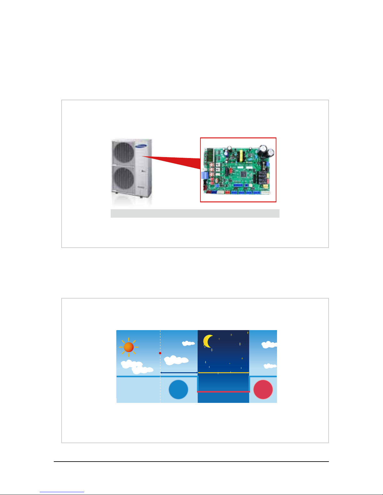
Operation
time
12 hours of silent mode6 hours
7 : 00 13 : 30 19 : 00 7 : 00
End
Highest temperature
※ 3 month wort h of data can be saved
when memo ry module is instal led
Black box function of the Main PCS
Feature (cont.)
Memory module
• Achieves world-class efficiency with hyper compressor that applies double compression technology
If outdoor unit malfunction occurs, diagnose and repair of the problem will be much quicker with the last 3 minutes worth of a data
saved before the malfunction. (With the extra memory module, 3 months worth of a data can be saved.)
Silent operation at nighttime
• When outdoor unit needs to operate more silently during nighttime, silent mode can be set from the outdoor unit option mode.
• Silent mode can be adjusted in 3 levels depending on the level of noise.

Product Specifications
8
Samsung Electronics
Refrigerant pump-down
If you need to move/replace the outdoor unit or when there are problems on indoor units or on the pipes, outdoor unit will recover
refrigerant remaining on the pipes.
Indoor unit
malfunction
Refrigerant recoveringsss
Feature (cont.)
System check through View mode
• Through the window on outdoor unit PCB display, you can check the main system data during operation.
• Shortened maintaining and inspection
• Displaying 15 main data including high pressure of system
- Outdoor temperature
- Discharge temperature of the compressor
- Condensing temperature
• Using the DIP switch on the outdoor unit PCB, you can limit the running current of the system

Product Specifications
Samsung Electronics
9
Feature (cont.)
Conventional
* For models w ith 9kW or larger (Flare t ype connection)
Convenient product installation
Service valve is not exposed to keep the neat appearance and pipe can be connected in 4 different directions which provide flexible
installation and maintenance services.
Maximum 9 indoor unit connection
Maximum 9 indoor unit connection
You may connect up to 9 indoor units on a single outdoor unit. It will allow more powerful and flexible air conditioning system
and you can select refrigerant pipe length, or number of indoor units depending on the needs for office, commercial and residential
places.
Product Specifications
10
Samsung Electronics
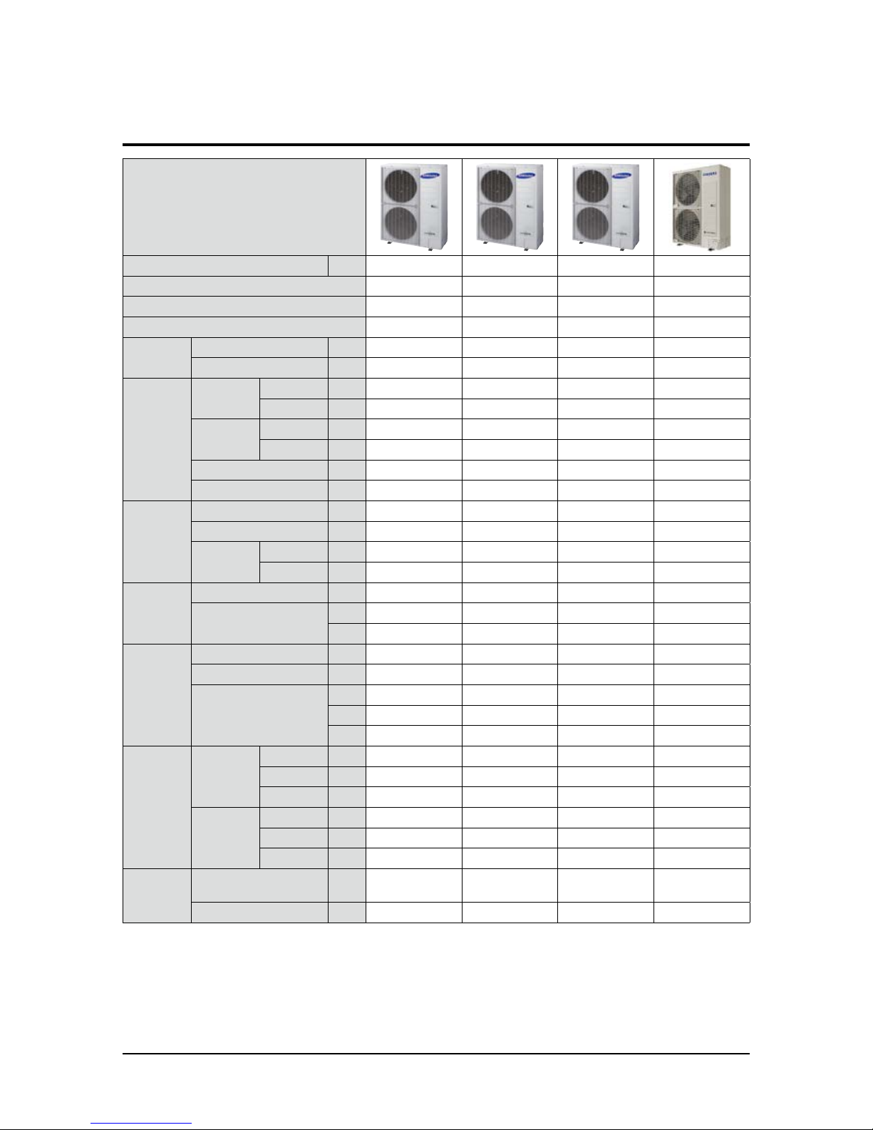
Type
Performance ton 3ton 4ton 4.5ton 5.0 ton
Model AM036NXMDCR AM048NXMDCR AM053NXMDCR AM060NXMDCR
Power Supply(Φ/V/Hz) 1,208-230,60 1,208-230,60 1,208-230,60 1,208-230,60
Mode HR HR HR HR
Performance
Cooling Btu/h 38,000 48,000 53,000 60,000
Heating Btu/h 42,000 54,000 61,000 66,000
Power
Running
Current
Cooling* A 15.0 20.3 25.6 23.0
Heating* A 16.4 21.3 26.1 23.5
Input
Cooling* W 3,100 4,200 5,300 5,200
Heating* W 3,400 4,400 5,400 5,300
MCA A 23 29 34 32
MOP A 40 50 50 50
Compressor
Type - Twin BLDC Inverter Twin BLDC Inverter Twin BLDC Inverter Scroll Inverter
Output W 4.04 4.04 4.04 ?
Lubricant
Type - PVE PVE PVE PVE
Charging cc 1700 1700 1700 2300
Refrigerant
Type - R410A R410A R410A R410A
Factory Charging
kg 3.2 3.2 3.3 3.7
lbs 7.1 7.1 7.3 8.2
FAN
Type - Propeller Fan Propeller Fan Propeller Fan Propeller Fan
Motor Output W 125x2 125x2 125x2 139x2
Airow rate
CMM 110 110 110 135
CFM 3,885 3,885 3,885 4,768
l/s 1,833 1,833 1,833 2,250
Pipe
Piping
connections
Liquid ø,mm 9.52 (3/8") 9.52 (3/8") 9.52 (3/8") 9.52 (3/8")
Sub Gas (HR) ø,mm 15.88 (5/8") 15.88 (5/8") 15.88 (5/8") 15.88 (5/8")
Gas ø,mm 19.05 (3/4") 19.05 (3/4") 19.05 (3/4") 19.05 (3/4")
Installation
Limitation
Max. Length m (ft) 300 (984) 300 (984) 300 (984) 300 (984)
Length m (ft) 150 (492) 150 (492) 150 (492) 150 (492)
Max. Height m (ft) 50 (164) 50 (164) 50 (164) 50 (164)
Cable
Main Power
(Below/about 20m)
mm2 CV 2.5/4.0 CV 2.5/4.0 CV 2.5/4.0 CV 2.5/4.0
Communication mm2 VCTF 0.75~1.5 VCTF 0.75~1.5 VCTF 0.75~1.5 VCTF 0.75~1.5
2. Product Specifications

Product Specifications
Samsung Electronics
11
Type
Performance ton 3ton 4ton 4.5ton 5.0 ton
Model AM036NXMDCR AM048NXMDCR AM053NXMDCR AM060NXMDCR
Set Size
Net weight
kg 97 97 100 125
lbs 213.8 213.8 220.5 275.6
Shipping Weight
kg 107 107 110 135
lbs 235.9 235.9 242.5 297.6
Net dimension (WxHxD)
mm 940 x 1210 x 330 940 x 1210 x 330 940 x 1210 x 330 1420 x 940 x 330
inch 37.01 x 47.64 x 12.99 37.01 x 47.64 x 12.99 37.01 x 47.64 x 12.99 55.91 x 37.00 x 12.99
Shipping dimension (WxHxD)
mm 995 x 1388 x 426 995 x 1388 x 426 995 x 1388 x 426 1578 x 995 x 426
inch 39.17 x 54.65 x 16.77 39.17 x 54.65 x 16.77 39.17 x 54.65 x 16.77 62.13 x 39.17 x 16.77
Operating
Temp. Range
Cooling
℉
23 ~ 118 23 ~ 118 23 ~ 118 23 ~ 118
Heating
℉
-13 ~ 75 -13 ~ 75 -13 ~ 75 -13 ~ 75
Maximum of connected indoor units 8 9 10 10
*
Rated Power/Current using Ducted indoor units

12
Samsung Electronics
Necessary Tools
■ Disassembly and Reassembly
Item Remark
+Screw Driver
Monkey Spanner
–Screw Driver
Nipper
Electric Motion Driver
L-Wrench
Disassembly and Reassembly
Samsung Electronics
13
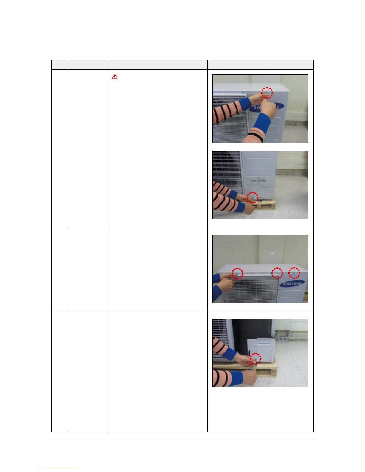
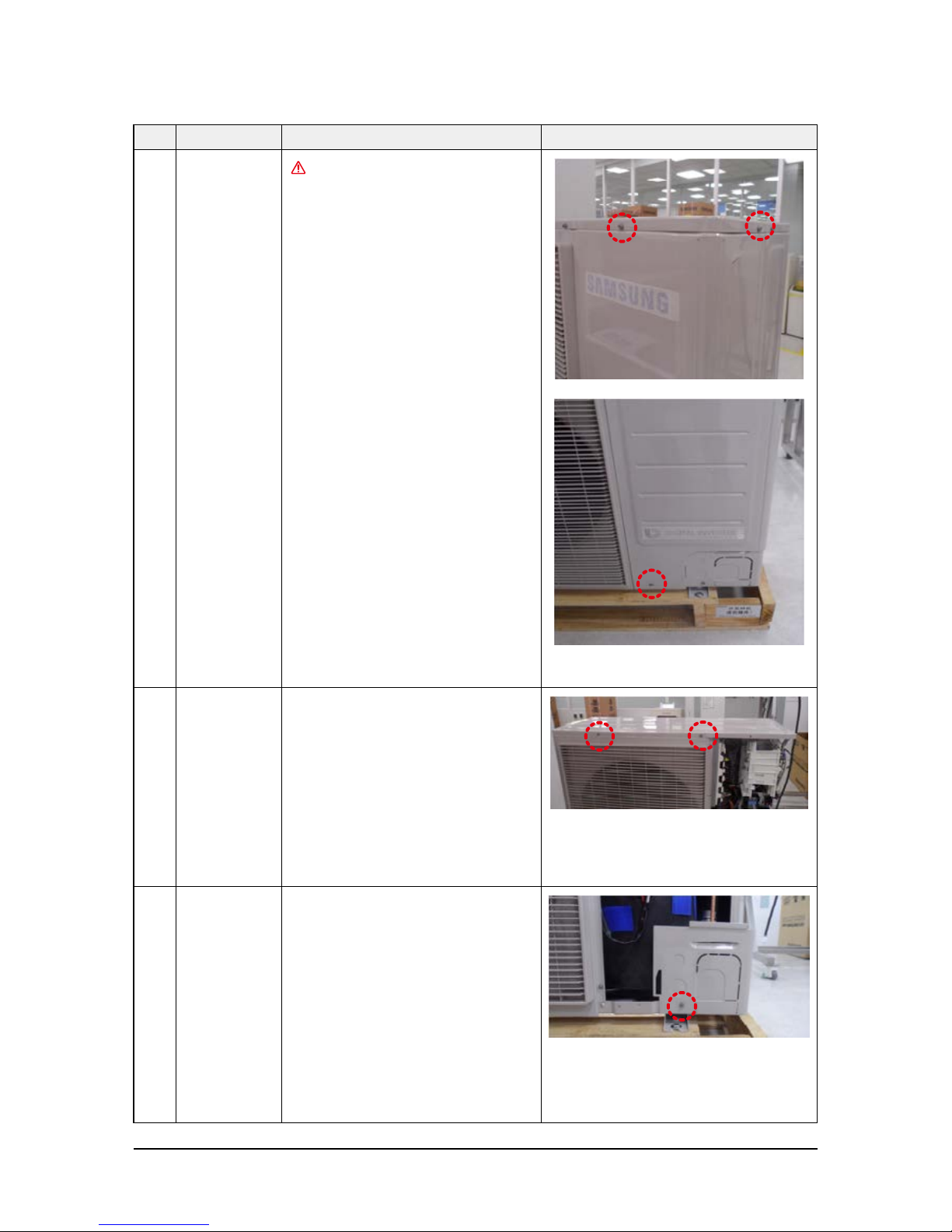
No Parts Procedure Remark
1 Cabi Front RH
You must turn off the Power before
disassembly.
1) Unscrew and remove 2 mounting screw in
the Cabinet Front RH. (Use + Screw Driver)
2 Cabi Top 1) Unscrew and remove 9 screws
on each side of the Cabinet-Top.
(Use +Screw Driver)
3 Cabi Install Front 1) Unscrew and remove 1 screw
in the Cabinet-Install Front.
(Use +Screw Driver)
AM036NXMDCR, AM048NXMDCR, AM053NXMDCR

Disassembly and Reassembly
14
Samsung Electronics
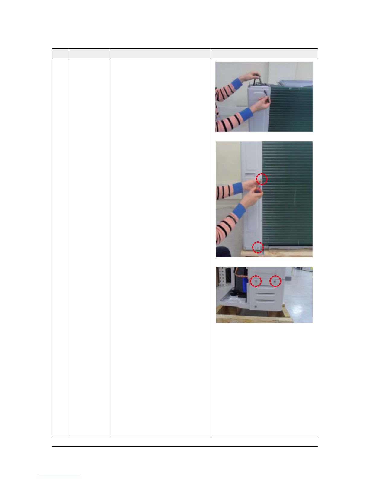
No Parts Procedure Remark
4 Guard Cond 1) Pull the sensor from Guard Cond.
2) Unscrew and remove 4 screws
in the Guard Cond. (Use + Screw Driver)
5 Cabi Back RH 1) Pull the sensor from Cabi Back RH.
2) Unscrew and remove 4 screws on
each side of the Cabinet Back RH.
(Use + Screw Driver)

Disassembly and Reassembly
Samsung Electronics
15
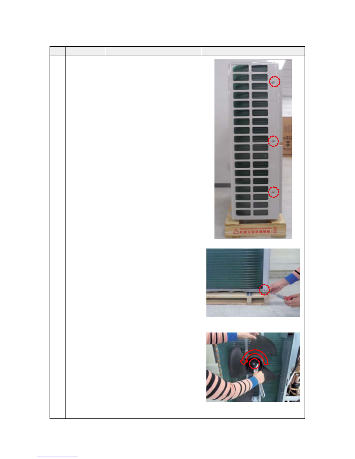
No Parts Procedure Remark
6 Cabi Install Back 1) Unscrew and remove 1 screw
in the Cabinet-Install Back.
(Use +Screw Driver)
7 Cabi Front LF 1) Unscrew and remove 10 screws
in the Cabinet-Front LF.
(Use +Screw Driver)

Disassembly and Reassembly
16
Samsung Electronics
No Parts Procedure Remark
8 Fan 1) Turn 2 mounting nuts as shown in the
picture and remove it.
(Use L Wrench or Monkey
Spanner or Socket Wrench )

Disassembly and Reassembly
Samsung Electronics
17
No Parts Procedure Remark
9 Motor 1) Separate the Fan Propeller.
2) Unscrew and remove the 8 Motor mounting
screws. (Use +Screw Driver)
3) Disconnect the Motor wire from
Ass’y Control Out.
10 Bracket Motor 1) Unscrew and remove 2 mounting screws in
Bracket Motor. (Use + Screw Driver)
Disassembly and Reassembly
18
Samsung Electronics
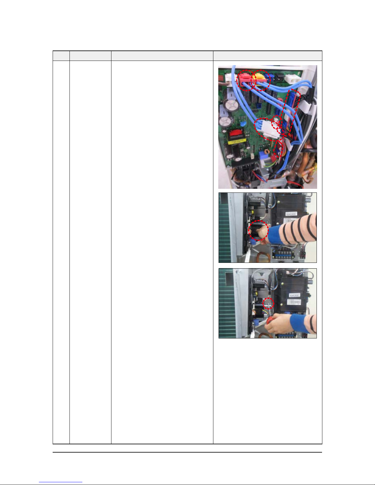
No Parts Procedure Remark
11 Control Out 1) Disconnect 10 Connectors from Ass’y control
Out.
2) Unscrew and remove 1 mounting screw in
Control Out. (Use + Screw Driver.)
3) Separate Ass’y Control Out.
Disassembly and Reassembly
Samsung Electronics
19
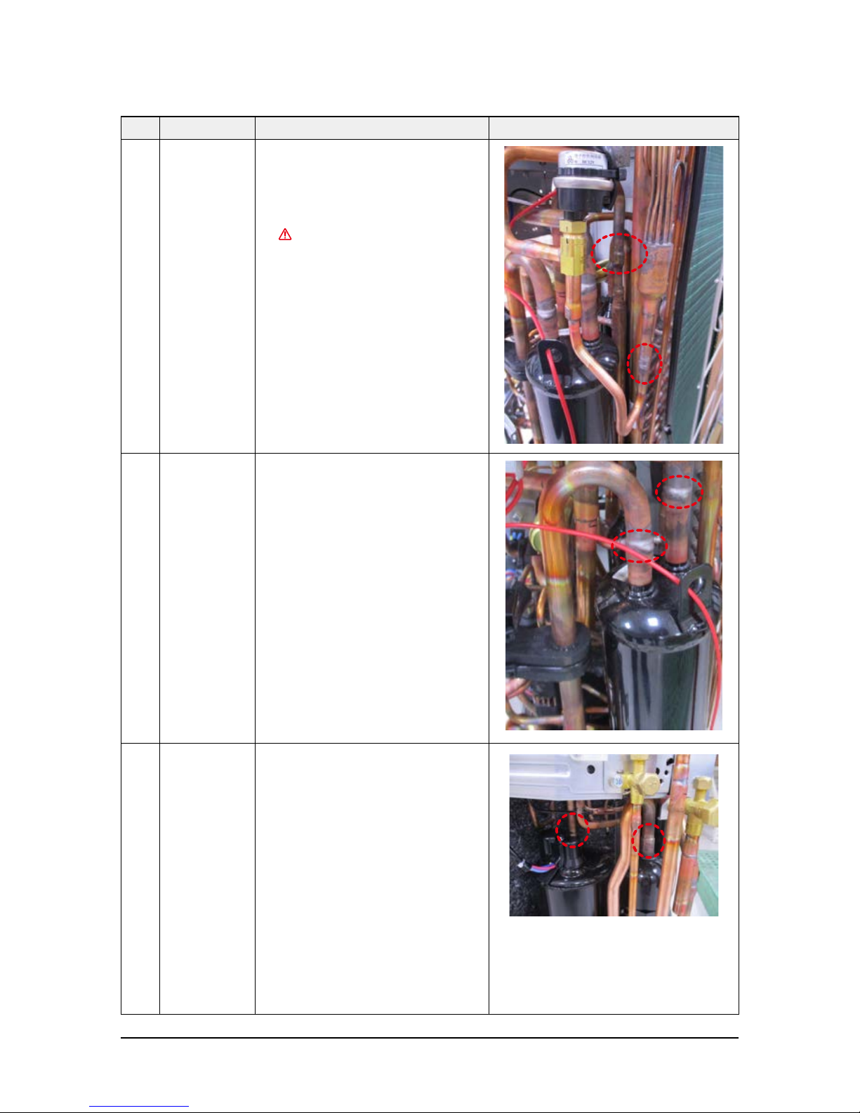
No Parts Procedure Remark
12 Ass'y Tube EEV 1) Purge the Coolant first.
2) Separate 2 parts of the pipe using a welder.
When removing the compressor,
Heat Exchanger and Pipe, purge the
refrigerant inside the Compressor
completely and remove the pipe with
a welding flame.
13 Ass'y Tube Suction 1) Separate 2 parts of the pipe using a welder.
14 Ass'y Tube 4Way 1) Separate 2 parts of the pipe using a welder.
Disassembly and Reassembly
20
Samsung Electronics
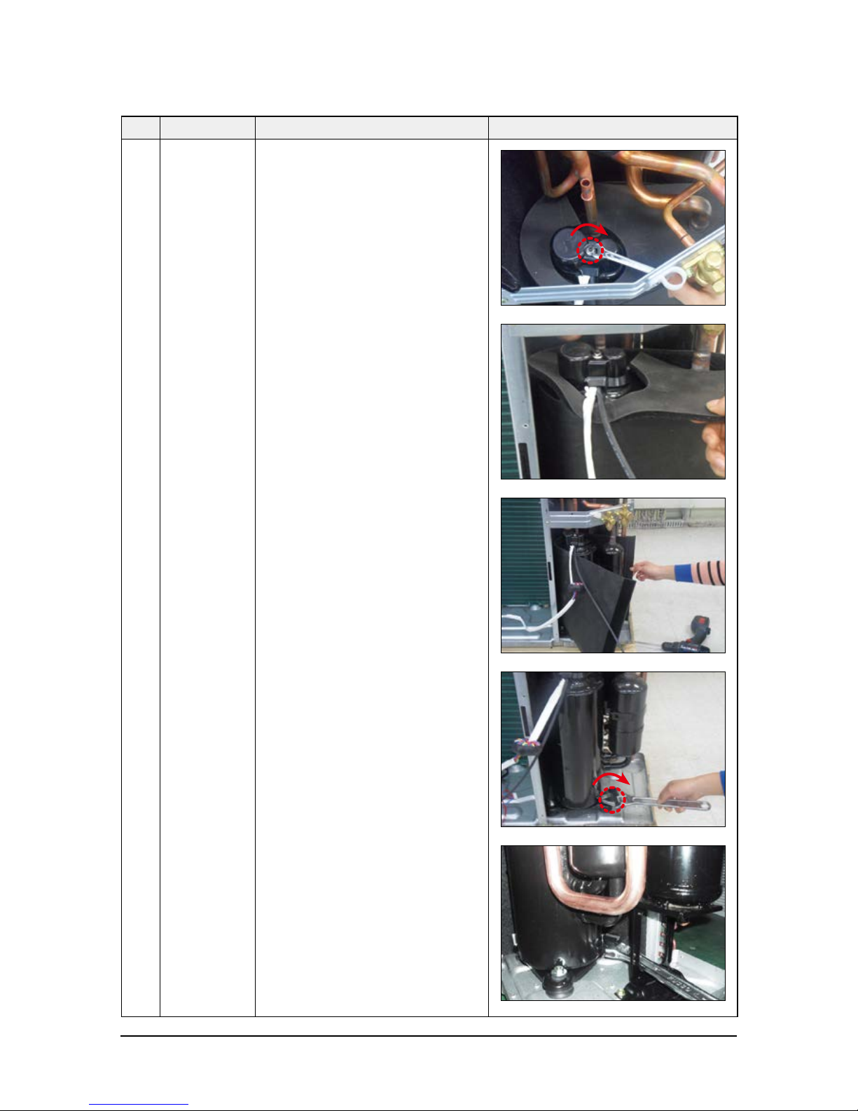
No Parts Procedure Remark
15 Compressor 1) Unscrew and remove 1 mounting
nut in bottom of the cover.
(Use Adjustable Wrench)
2) Separate the Compressor Felt.
3) As shown in the picture, unscrew and
remove 3 mounting screws from the bottom.
(Use L-Wrench or Monkey Spanner or
Socket Wrench)

Disassembly and Reassembly
Samsung Electronics
21
No Parts Procedure Remark
16 Cond Out 1) Unscrew and remove 3 screws
on each side of the Ass’y Cond Out.
(Use + Screw Driver)
Disassembly and Reassembly
22
Samsung Electronics
No Parts Procedure Remark
1 Cabi Front RH
You must turn off the Power before
disassembly.
1) Unscrew and remove 3 mounting screw in|
the Cabinet Front RH. (Use + Screw Driver)
2 Cabi Top 1) Unscrew and remove 8 screws on each side of
the Cabinet-Top. (Use +Screw Driver)
3 Cabi Install Front 1) Unscrew and remove 1 screw in the Cabinet
Install Front. (Use +Screw Driver)
AM060NXMDCR

Disassembly and Reassembly
Samsung Electronics
23
No Parts Procedure Remark
4 Guard Cond 1) Pull the sensor from Guard Cond.
2) Unscrew and remove 4 screws in the Guard Cond.
(Use + Screw Driver)
Disassembly and Reassembly
24
Samsung Electronics
No Parts Procedure Remark
5 Cabi Back RH 1) Pull the sensor from Cabi Back RH.
2) Unscrew and remove 4 screws on
each side of the Cabinet Back RH.
(Use + Screw Driver)

Disassembly and Reassembly
Samsung Electronics
25
No Parts Procedure Remark
5 Cabi Back RH 3) Unscrew and remove 5 screws on
side of the Case Bracket valve.
(Use + Screw Driver)
6 Cabi Install Back 1) Unscrew and remove 1 screw in the Cabinet
Install Front. (Use +Screw Driver)

Disassembly and Reassembly
26
Samsung Electronics
No Parts Procedure Remark
7 Cabi Front LF 1) Unscrew and remove 10 screws in the
Cabinet-Front LF. (Use +Screw Driver)
Disassembly and Reassembly
Samsung Electronics
27
No Parts Procedure Remark
7 Cabi Front LF
8 Fan 1) Turn 2 mounting nuts as shown in the
picture and remove it. (Use L Wrench
orMonkey Spanner or Socket Wrench )

Disassembly and Reassembly
28
Samsung Electronics
No Parts Procedure Remark
9 Motor 1) Separate the Fan Propeller.
2) Unscrew and remove the 8 Motor mounting
screws. (Use +Screw Driver)
3) Disconnect the Motor wire from
Ass’y Control Out.
10 Bracket Motor 1) Unscrew and remove 2 mounting screws
in Bracket Motor. (Use + Screw Driver)
 Loading...