

Samsung AM120FXWANR, AM100FXWANR, AM072HXWAFR, AM096HXWAFR, AM120HXWAFR Service Manual
...
AIR CONDITIONER CONTENTS
SYSTEM AIR CONDITIONER
OUTDOOR UNIT
AM080/100/120/200FXWANR6 / AM300KXWANR6
AM072/096/120/192HXWAFR6 / AM240KXWAFR6
AM072/096/120/192HXWAJR6 / AM240KXWAJR6
AM038/048/055KXWDCH6
1. Precautions
2. Product Specifications
3. Disassembly and Reassembly
4. Troubleshooting
5. PCB Diagram and Parts List
6. Wiring Diagram
7. Piping Diagram
8. Key Options
9. Test Operation
10. Nomenclature.

Section 0
Samsung Electronics 1
Contents
1. Precautions ....................................................................................................................................................1
1-1 Precautions for the Service ..................................................................................................................................................1
1-2 Precautions for the Static Electricity and PL .................................................................................................................1
1-3 Precautions for the Safety ....................................................................................................................................................1
1-4 Precautions for Handling Refrigerant for Air Conditioner ...................................................................................... 2
1-5 Precautions for Welding the Air Conditioner Pipe ..................................................................................................... 2
1-6 Precautions for Additional Supplement of Air Conditioner Refrigerant .......................................................... 2
1-7 Other Precautions ...................................................................................................................................................................2
2. Product Specifications ................................................................................................................................. 3
2-1 Feature of Product ..................................................................................................................................................................3
2-1-1 Feature ..............................................................................................................................................................................3
2-1-2 Changes in comparison to basic model (AM300KXWANR) .......................................................................4
2-1-2 Changes in comparison to basic model (AM240KXWAFR) ........................................................................4
2-1-3 Structure of product (AM038/048/055KXWDCH Series) ...........................................................................10
2-1-4 Structure of product
(Small size : AM080/100FXWANR* / AM072/096/120HXWAFR*
(Large size : AM200FXWANR*,AM300KXWANR* / AM192HXWAFR*,AM240KXWAFR*) ............11
2-1-5 Structure of product
(Power supply for 460V, 60Hz, 3Φ : AM072/096/120/192/240*XWAJR Series)
.12
غ 3~6HP DVM S Water : Exploded View ........................................................................................................13
- AM038/048/055KXWD*** ....................................................................................................................................13
غ 8~12HP DVM S Water : Exploded View .......................................................................................................14
- AM080/100/120FXWA*** ......................................................................................................................................14
- AM072/096/120HXWA*** .....................................................................................................................................14
غ 20/30HP DVM S Water : Exploded View ......................................................................................................15
- AM200/300*XWA*** ...............................................................................................................................................15
- AM192/240*XWA*** ................................................................................................................................................15
2-2 Model names of Indoor/Outdoor Unit ........................................................................................................................ 16
2-2-1 Outdoor unit combination .....................................................................................................................................16
غ Premium Energy Efficiency Type (AM***FXWANR*) ...............................................................................16
غ Premium compact type (AM***KXWANR*) .................................................................................................16
غ Premium Energy Efficiency Type (AM***KXWDCH*) ..............................................................................17
غ Premium Energy Efficiency Type (AM***HXWAF(J)R*) ...........................................................................18
غ Premium compact type (AM***KXWAF(J)R*) .............................................................................................18
2-2-2 Indoor unit.....................................................................................................................................................................19
2-2-3 Outdoor unit ................................................................................................................................................................21
غ Premium Energy Efficiency Type (AM***FXWANR*) ..............................................................................21
غ Premium Compact Type (AM***KXWANR*)............................................................................................... 22
غ Premium Energy Efficiency Type (AM***KXWDCH*) ............................................................................ 23
غ Premium Energy Efficiency Type (AM***HXWAF(J)R*) ......................................................................... 23
غ Premium compact type (AM***KXWAF(J)R*) .............................................................................................24
2-3 Combination and Connection Ratio limitation ....................................................................................................... 25
2-4 Components and Feature ................................................................................................................................................. 26
2-5 Product Specification ......................................................................................................................................................... 27
2-5-1 Outdoor Unit ...........................................................................................................................................................27
2-6 Accessory and Option Specifications ........................................................................................................................... 31
2-6-1 Controller ......................................................................................................................................................................31
2-6-2 Piping ............................................................................................................................................................................. 34
2-6-3 Indoor .............................................................................................................................................................................35
2-6-4 Controller & control Accessory Compatibility ..............................................................................................37
2-6-5 Indoor units Accessory Compatibility ............................................................................................................. 38

Samsung Electronics 2
Section 0
Contents
3. Disassembly and Reassembly ...................................................................................................................40
3-1 Necessary Tools .................................................................................................................................................................... 40
3-2 Disassembly and Reassembly ......................................................................................................................................... 41
3-2-1 Checking the Device Condition ...........................................................................................................................41
3-2-2 Removal Instructions for Panel ............................................................................................................................42
3-2-3 Disconnecting the Power Supply .......................................................................................................................43
3-2-4 Removal Instructions for Compressor ............................................................................................................. 46
3-2-5 Compressor exchange order ............................................................................................................................. 48
3-2-6 Removal Instructions for Tank ............................................................................................................................. 50
3-2-7 Removal Instructions for the Hub PBA ............................................................................................................54
3-2-8 Removal Instructions for the Control Panel Assy ........................................................................................ 56
3-2-9 Removal Instructions for the Inverter PBA ......................................................................................................59
3-2-10 Removal Instructions for the DC Reactors and EMI PBA .........................................................................62
4. Troubleshooting ..........................................................................................................................................64
4-1 Check-up Window Description ....................................................................................................................................... 64
- AM038/048/055KXWDCH* ............................................................................................................................................ 64
- AM080/100/120/200FXWANR*, AM300KXWANR* / AM072/096/120/192HXWAF(J)R*,
AM240KXWAF(J)R* ............................................................................................................................................................ 66
4-2 Service Operation ................................................................................................................................................................. 67
4-2-1 Special Operation .....................................................................................................................................................67
-
AM080/100/120/200FXWANR*, AM300KXWANR* / AM072/096/120/192HXWAF(J)R*, AM240KXWAF(J)R*
...67
- Key input of the outdoor unit when the service enters the operation mode. ........................................67
4-2-2 DVM S Models EEPROM Code Table ................................................................................................................. 73
4-2-3 Number Display Method (Outdoor Unit, MCU, Cable remote control, wall-mount, etc.) ..........74
4-3 Appropriate Measures for Different Symptom ........................................................................................................ 79
4-3-1 Outdoor Unit Test Operation Flow....................................................................................................................79
4-3-2 Main PBA has no power phenomenon ..........................................................................................................83
4-3-3 Communication Error between Indoor and Outdoor Units during Tracking ...............................84
4-3-4 Communication Error between Indoor and Outdoor Units after Tracking ...................................86
4-3-5
Communication error between main and sub Unit of outdoor unit or between outdoor units
..87
4-3-6 Internal Communication error of the Outdoor Unit C-Box ................................................................... 88
4-3-7 Internal PBA Communication error of the Outdoor Unit C-Box ..........................................................89
4-3-8 MCU branch part setup error – inconsecutive connection with the use of 2 branch parts ....91
4-3-9 MCU branch part setup error – Repeated setup for the same address over 3 times .................92
4-3-10 MCU branch part setup error – non-installed address setup .............................................................93
4-3-11 Setup Error for MCU Branch part – Setup Error for MCU Quantity Used........................................ 94
4-3-12 MCU branch part setup error – Overlapping Indoor unit Address setup ..................................... 95
4-3-13 MCU branch part setup error – Set as being used without connection to an Indoor unit .. 96
4-3-14 MCU branch part setup error – Connect an Indoor unit to a branch part not being used ...97
4-3-15
MCU branch part setup error – Connect more Indoor units than what is actually set up in MCU
.98
4-3-16 MCU/MCU subcooler entrance/exit sensor error (Open/Short) ......................................................... 99
4-3-17 Outdoor Temperature Sensor Error .............................................................................................................100
4-3-18 Cond Out Temperature Sensor Error (Open/Short) .............................................................................. 101
4-3-19 Outdoor Cond Out sensor breakaway error ............................................................................................ 102
4-3-20 Compressor Discharge or Top 1/2 Temperature sensor error .........................................................104
4-3-21 Compressor Discharge or Top temperature sensor breakaway error .......................................... 105
4-3-22
: Suction Temperature sensor breakaway error ...............................................................106
4-3-23 High Pressure sensor error (Open/Short) .................................................................................................107
4-3-24 Low Pressure sensor error (Open/Short) ...................................................................................................108

Section 0
Samsung Electronics 3
Contents
4-3-25 Suction Temperature sensor error (Open/Short) ..................................................................................109
4-3-26 Liquid Pipe Temperature sensor error (Open/Short) ............................................................................110
4-3-27 EVI In Temperature sensor error (Open/Short)........................................................................................111
4-3-28 EVI Out Temperature sensor error (Open/Short) ...................................................................................112
4-3-29 Suction-2 Temperature Sensor Error (OPEN/SHORT) .............................................................................113
4-3-30 Measures of other outdoor unit error ..........................................................................................................114
4-3-31
: Comp. Down due to High Pressure Protection Control ..............................................115
4-3-32
: Comp. Down due to Low Pressure Protection Control ...............................................116
4-3-33
: Suspension of starting due to Compressor discharge temperature sensor
/ Top temperature sensor ......................................................................................................118
4-3-34 3-phase Input Wiring error ..............................................................................................................................119
4-3-35
: Suspension of starting by abnormal compression ratio ............................................. 120
4-3-36 EVI EEV Open error ..............................................................................................................................................121
4-3-37 Refrigerant leakage error ................................................................................................................................. 122
4-3-38 Prevention of heating / cooling operation due to outdoor temperature .................................. 123
4-3-39 Prevention of heating refrigerant charge due to outdoor temperature ....................................124
4-3-40 CCH wire breaking error ..................................................................................................................................125
4-3-41 Momentary Blackout error ............................................................................................................................ 126
4-3-42 Compressor starting error ................................................................................................................................ 127
4-3-43 COMP Overcurrent error ...................................................................................................................................129
4-3-44 Overvoltage / Low voltage error................................................................................................................... 133
4-3-45 DC Link voltage sensor error .........................................................................................................................134
4-3-46 Input / Output Current sensor error ........................................................................................................... 135
4-3-47 Inverter PBA IPM overheating error ............................................................................................................136
4-3-48 Option setting error of outdoor unit........................................................................................................... 137
4-3-49 Error due to using single type outdoor unit in a module installation ..........................................138
4-3-50 Indoor unit and MCU address duplication error ....................................................................................139
4-4 Case study for trouble shoots .......................................................................................................................................140
4-4-1 Electric discharge mode ......................................................................................................................................140
4-4-2 Pump down operation ......................................................................................................................................... 143
4-4-3 Pump out operation ............................................................................................................................................. 145
4-4-4 Vacuum ....................................................................................................................................................................... 147
4-4-5 Case study – E201 (Communication error between indoor & outdoor unit) ...............................148
4-4-6 Case study – E205 (Internal communication error of the outdoor unit C-box) ..........................150
4-4-7 Case study – E206 (Internal communication error of the outdoor unit C-box) ........................... 151
4-4-8 Case study – E108 (Error due to repeated address setting) ................................................................. 152
4-4-9 Case study – E108, E604, E613 ......................................................................................................................... 153
4-4-10 Case study – E461, E361 (Error due to operation failure of inverter compressor) ....................154
4-4-11 Case study – Inverter PBA error ...................................................................................................................... 155
4-4-12 Case study – E461/361 & E464/364 & E466/366 ...................................................................................... 156
4-4-13 Case study – Poor cooling caused by IPM overheated ........................................................................160
4-4-14 Case study – Related error with IPM ............................................................................................................162
4-4-15 Case study – Temperature sensor open/short ........................................................................................163
4-4-16 Case study – Pressure sensor open/short.................................................................................................. 164

Samsung Electronics 4
Section 0
Contents
5. PBA Diagram and Parts List .........................................................................................................................................165
5-1 ASS'Y PBA MAIN .................................................................................................................................................... 165
غ Push buttons Type ...........................................................................................................................................165
غ DIP S/W Type .....................................................................................................................................................167
5-2 ASS'Y PBA MAIN-HUB ....................................................................................................................................... 169
غ AC ............................................................................................................................................................................169
غ DC ...........................................................................................................................................................................171
5-3 ASSY PBA INVERTER ........................................................................................................................................... 173
- Model : AM080/100/120/200FXWANR* / AM072/096/120/192HXWAF(J)R* ........................................... 173
- Model : AM300KXWANR* / AM240KXWAF(J)R* ................................................................................................. 175
5-4 ASS’Y PBA EMI ...................................................................................................................................................... 177
- Model : AM080/100/120/200FXWANR* / AM072/096/120/192HXWAF(J)R* ........................................... 177
- Model : AM300KXWANR* / AM240KXWAF(J)R* ................................................................................................. 178
5-5 SUB-COMM ............................................................................................................................................................ 180
6. Wiring Diagram .............................................................................................................................................................. 181
6-1 AM080/100/120/200FXWA** ......................................................................................................................... 181
6-2 AM300FXWA** ..................................................................................................................................................... 184
6-3 Field Wiring ............................................................................................................................................................. 185
7. Piping Diagram ..............................................................................................................................................................188
7-1 Piping Diagram ..................................................................................................................................................... 188
7-1-1 AM300KXWANR*, AM240KXWAF(J)R* (DVM S Water Heat Recovery) ................................190
7-1-2 AM200FXWANR*, AM192HXWAF(J)R (DVM S Water Heat Recovery) ..................................191
7-1-3 AM300KXWANR*, AM240KXWAF(J)R* (DVM S Water Heat Recovery) ...............................192
7-2 Refrigerant Flow for Each Operation Mode .............................................................................................. 193
7-2-1 Cooling operation(H/R) ...........................................................................................................................193
7-2-2 Main cooling operation(H/R) .................................................................................................................194
7-2-3 Heating operation(H/R) ..........................................................................................................................195
7-2-4 Main heating operation(H/R) ................................................................................................................196
7-3 Functions ................................................................................................................................................................. 197
7-3-1 Basics................................................................................................................................................................197
8. Key Options ..................................................................................................................................................................... 259
8-1 System Configuration ......................................................................................................................................... 259
8-2 List of Field Setting Items ................................................................................................................................. 260
8-3 Outdoor unit option switch settings ........................................................................................................... 261
8-4 How to check the view mode using a tact switch ...............................................................................................266
8-5 Applications ......................................................................................................................................................... 269
8-5-1 Application of Auxiliary Heat Module ............................................................................................269
8-5-2 Application of Mode select Switch ..................................................................................................272
9. Test Operation ................................................................................................................................................................ 278
9-1 Auto Trial Operation ............................................................................................................................................ 278
9-1-1 Overview of Auto Trial Operation .......................................................................................................278
9-1-2 Auto Trial Operation Flow Chart ..........................................................................................................281
9-1-3 How to resolve NG items ........................................................................................................................282
9-2 Amount of refrigerant automatically checking ...................................................................................... 292
10. Nomenclature .............................................................................................................................................................. 293
10-1 Model Naming ................................................................................................................................................... 293

Samsung Electronics 1
1. Precautions
1-1 Precautions for the Service
OUse the correct parts when changing the electric parts.
– Please check the labels and notices for the model name, proper voltage, and proper current for the electric parts.
OFully repair the connection for the types of harness when repairing the product after breakdown.
– A faulty connection can cause irregular noise and problems.
OWhen disassembling or assembling, make sure that the product is laid down on a work cloth.
– Doing so will prevent scratching to the exterior of the rear side of the product.
OCompletely remove dust or foreign substances on the housing, connection, and inspection parts when performing repairs.
– This can prevent fire hazards for tracking, short, etc.
OPlease tighten the service valve of the outdoor unit and the valve cap of the charging valve as securely as possible by using
a monkey spanner.
OCheck whether the parts are properly and securely assembled after performing repairs.
– These parts should be in the same condition as before the repair.
1-2 Precautions for the Static Electricity and PL
OPlease carefully handle the PBA power terminal during repair and measurement when it is turned on since it is vulnerable
to static electricity.
– Please wear insulation gloves before performing PBA repair and measurement.
OCheck if the place of installation is at least 2m away from electronic appliances such as TV, video players, and stereos.
– This can cause irregular noise or degrade the picture quality.
OPlease make sure the customer does not directly repair the product.
– Arbitrary dismantling may result in electric shock or fire.
1-3 Precautions for the Safety
ODo not pull or touch the power plug or the subsidiary power switch with wet hands.
– This may result in electric shock or fire.
OIf the power line or the power plug is damaged, then it must be changed since this is a hazard.
ODo not bend the wire too much or position it so that it can be damaged by a heavy object on top.
– This may result in electric shock or fire.
OThe use of multiple electric outlets should be prohibited.
– This may result in electric shock or fire.
OGround the connection if it is necessary.
– The connection must be grounded if there is any risk of electrical short due to water or moisture.
OUnplug the power or turn off the subsidiary power switch when changing or repairing electrical parts.
– Doing so will prevent electric shock.
OExplain to workers that the battery for the remote control needs to be separated for storage purposes when the product
will not be used for a long time.
– This can cause a problem for the remote control since battery fluid may trickle out.

Samsung Electronics 2
Precautions
1-4 Precautions for Handling Refrigerant for Air Conditioner
Environmental Cautions: Air pollution due to gas release
OSafety Cautions
If liquid gas is released, then body parts that come into contact with it may experience frostbite/blister/numbness.
If a large amount of gas is released, then suffocation may occur due to lack of oxygen. If the released gas is heated, then noxious
gas may be produced by combustion.
OContainer Handling Cautions
Do not subject container to physical shock or overheating. (Flowage is possible while moving within the regulated pressure.)
1-5 Precautions for Welding the Air Conditioner Pipe
ODangerous or flammable objects around the pipe must be removed before the welding.
OIf the refrigerant is kept inside the product or the pipe, then remove the refrigerant prior to welding.
If the welding is carried out while the refrigerant is kept inside, the welding cannot be properly performed. This will also produce
noxious gas that is a health hazard. This leakage will also explode with the refrigerant and oil due to an increase in the refrigerant
pressure, posing a danger to workers.
OPlease remove the oxide produced inside the pipe during the welding with nitrogen gas.
Using another gas may cause harm to the product or others.
1-6 Precautions for Additional Supplement of Air Conditioner Refrigerant
OPrecisely calculate the refrigerant by using a scale and S-net, and proceed with the test operation.
Excessive supplement can cause harm to the product since it can cause an inflow of the liquid refrigerant into the compressor.
ODo not heat the refrigerant container for a forced injection.
This may cause harm to the product or others since the refrigerant container may burst.
ODo not operate the product after removing the product safety pressure switch and sensor.
If the product is blocked inside, then this may cause harm to the product or others due to the excess pressure increase of the
refrigerant gas.
1-7 Other Precautions
OThere should be no leakage of the pipes after installation. When withdrawing the refrigerant, the compressor should be
stopped before removing the connecting pipe.
If the compressor is operating while the refrigerant pipe is not correctly connected and the service valve is opened, then
air and other substances can enter the pipe. The interior of the refrigerant cycle may then build up excessive high pressure
resulting in explosion and damage.
Samsung Electronics 3
2. Product Specifications
2-1 Feature of Product
2-1-1 Feature
More ecient, more eco-friendly
The DVM S WATER air conditioning system saves money and the environment,
while providing a powerful performance. Its innovative Dual Inverter Compressor with a high eciency Vapor Injection System ensures powerful, rapid cooling and heating with minimum energy consumption, so it’s very eco-friendly. A
Plate Heat Exchanger also improves the heat exchange eciency and ensures
stable cooling and heating performances.
Flexible installation almost anywhere
The DVM S WATER air conditioning system can be installed almost anywhere,
regardless of its location or distance from the building.
It has a maximum piping length of up to 170 meters (558 feet) between the outdoor and indoor units, while still ensuring complete reliability. It can also reach
up to a height of 50 meters (164 feet), which is the equivalent of 10 stories.
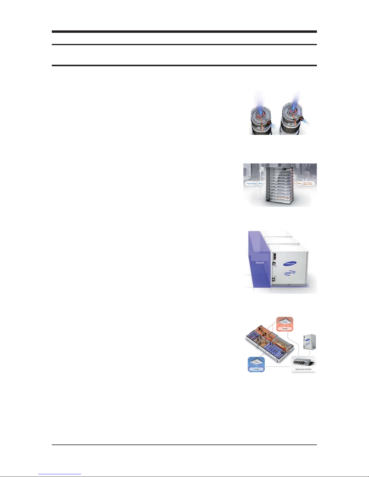
Lower installation costs, great capacity
The DVM S WATER air conditioning system is much more economical to install as
it has a small footprint and lightweight design, but a large 30 horsepower (HP)
capacity.
So instead of installing three 10HP units you only need one 30HP Samsung unit
– using 56% less space and signicantly reducing the costs of valves, ttings and
gauges. You can also combine up to three units to create a total capacity of
90HP.
Independently cool and heat
With the DVM S WATER air conditioning system’s optional Mode Control Unit
(MCU) you can independently cool and heat dierent spaces at the same time.
Instead of just heating or cooling all spaces at the same time, with the MCU each
indoor unit can be operated separately, so you can simultaneously heat some
rooms or areas of the building, while cooling others.
30HP
56%
30HP
30HP
Samsung Electronics 4
Product Specifications
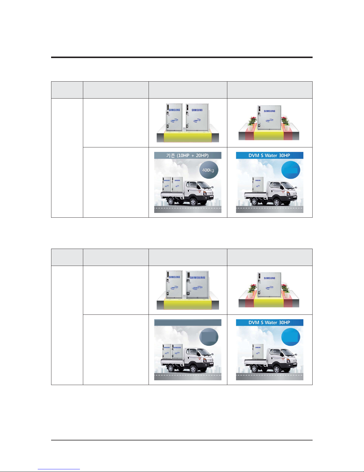
2-1-2 Changes in comparison to basic model (AM300KXWANR)
2-1-2 Changes in comparison to basic model (AM240KXWAFR)
2-1 Feature of Product (cont.)
Changed Part Changed item And feature
Basic
(10HP+20HP)
After changed
(DVM S Water 30HP)
Cabinet
Save Installation Space by
40% compared to basic
1.0 m
2
0.6 m
2
40%
Save
Save Weight by 30%
Compared to basic
280kg
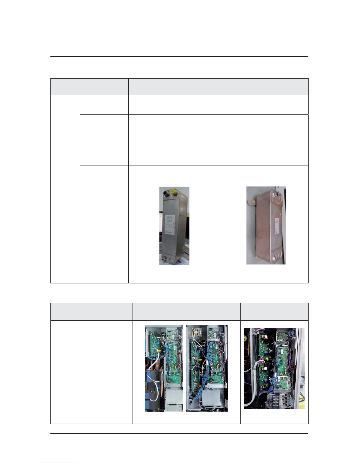
Changed Part Changed item And feature
Basic
(10Ton + 10Ton)
After changed
(DVM S Water 20Ton)
Cabinet
Save Installation Space by
33% compared to basic
1.0 m
2
0.6 m
2
33%
Save
Save Weight by 15%
Compared to basic
Basic(10Ton + 10Ton)
320kg
(706lbs)
274kg
(604lbs)
Product Specifications
Samsung Electronics 5
Changed
Part
Changed item
And feature
Basic
After changed
(AM300KXWANR/AM240KXWAF(J)R)
Compressor
AM***F(K)XWANR :
52/66cc ױ70cc
8/10HP : 52CC
12HP : 66CC
20HP : 52CC
30HP : 70CC
AM***H(K)XWA*R :
52cc ױ 66cc
6/8/10Ton : 52cc x 1
16Ton : 52cc x 2
20Ton : 66cc x 2
Plate Heat
Exchanger
Capacity Up 8,10,12HP / 20HP 30HP
Size UP (W x H x D)
8/10/12HP (mm) : 770x1,000x545
6/8/10Ton (inch) : 30.3x39.4x21.5
20HP (mm) : 1,100x1,000x545
16Ton (inch): 1,100(43.3)x1,000(39.4)x545(21.5)
30HP (mm) : 1,100x1,000x545
20Ton (inch) : 43.3x39.4x21.5
Socket Size Up PT 1-1/4"
PT2" (for Europe)
6/8/10/16Ton : NPT 1-1/4
20Ton : NPT 2
Picture
AM080/100/120/200FXWANR
AM072/096/120/196FXWAF(J)R
AM300KXWANR/
AM240KXWAF(J)R
Changed
part
Changed item
and feature
AM080/100/120/200FXW*
AM72/096/120/196HXW*
AM300KXW*
AM240KXW*
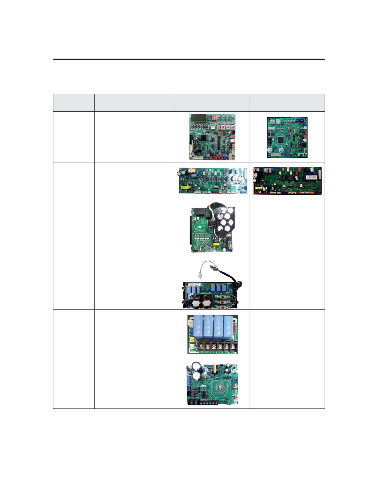
CONTROL
BOX
- PBA & WIRE SIZE change
. INV : 260*240 ĺ 292*242
. EMI : 230*130 ĺ 242*145
. Power WIRE : #12 ĺ #8
- Large IPM cooling
<8/10/12HP> <20HP>
<30HP>
Q Control Box & PBA
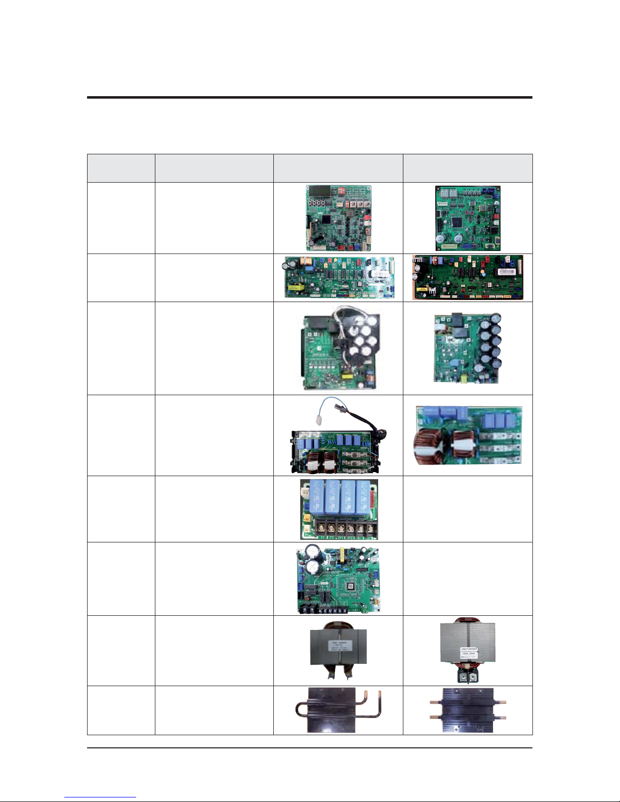
2-1-2 Changes in comparison to basic model (cont.)
2-1 Feature of Product (cont.)
Samsung Electronics 6
Product Specifications
2-1-2 Changes in comparison to basic model (cont.)
Q
AM80/100/120/200FXWA66
2-1 Feature of Product (cont.)
Changed part
Changed item
and feature
Basic After changed
Main PCB
Change Main PCB
- Separation for load / control.
- Option resistance delete by model.
(standardization)
- When do PCB replace, need
ption download.
Hub PCB
Hub PCB newly application
- Separation for load / control.
- Enhanced fixing of load /
sensor wire.
Inverter PCB
(Compressor
Control PCB)
Applied inverter Compressor.
- Refrigerant cooling method.
- Magnet S/W
ױ Did Power Relay mount to PCB.
ׯ
EMI PCB
3 phase power EMI PCB
- Fuse mount
ׯ
Communication
Terminal block
Did Communication Terminal block
mount to PCB.
ׯ
Water Hub PCB
Water Hub PCB
- External contact for DVM S WATER
ׯ
Product Specifications
Samsung Electronics 7
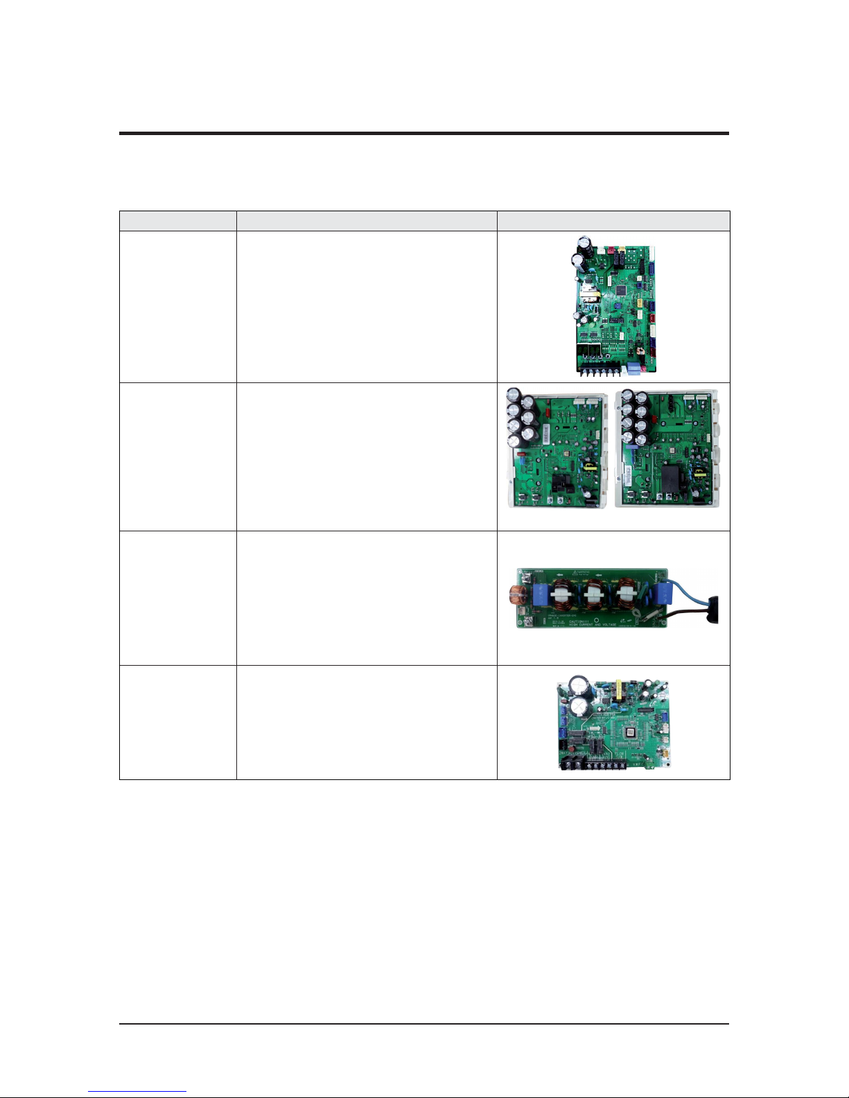
2-1-2 Changes in comparison to basic model (cont.)
Changed part Changed item and feature Basic (AM240KXWAF(J)R) After changed (AM196HXWAF(J)R)
Main PBA
Change Main PBA
- Increase MICOM capability
Hub PCB
Hub PCB newly application
- Separation for load / control.
- Enhanced fixing of load /
sensor wire.
Inverter PBA
(Compressor
Control
PBA)
- Increases current due to
high capacity compressor
- Increases capacitor's capacity
- Applies EMI coil on board
(Deletes core in wire)
EMI PBA
- Develops 50A EMI PBA
ױIncreases coil size and
fuse capacity
- Improves EMI characteristic.
Communication
Terminal block
Did Communication Terminal block
mount to PCB.
ׯ
Water Hub PCB
Water Hub PCB
- External contact for DVM S WATER
ׯ
REACTOR
- Increases current due to
high capacity compressor
- Improved wire connection termi-
nal
Refrigerant
cooling
- Increases heat cooling capacity
- Increases pipe size and heat
exchange area
Q
AM240KXWAF(J)R
2-1 Feature of Product (cont.)
Samsung Electronics 8
Product Specifications
2-1-2 Changes in comparison to basic model (cont.)
Q
AM038/048/055KXWD
66
2-1 Feature of Product (cont.)
Item Feture PBA
Main PCB
Main PCB
- Separation for load / control.
- Option resistance delete by model. (standardization)
- When replace the PCB, must download option.
- Enhanced fixing of load / control wire.
Inverter PCB
(Compressor control
PCB)
Compressor control
Inverter PCB
3/4HP:PF#4 5/6HP : PF#5
EMI PCB
Single-phase power supply EMI PCB
- FUSE mount
Water Hub PCB
Water Hub PCB
-The external contact point of the water-cooled.
Product Specifications
Samsung Electronics 9
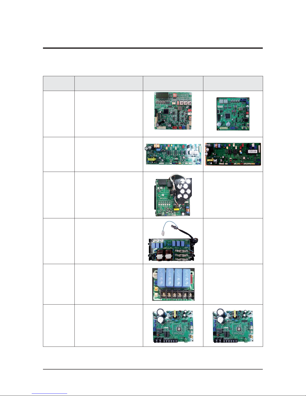
2-1-2 Changes in comparison to basic model (cont.)
Q
AM072/096/120/192HXWA
66
2-1 Feature of Product (cont.)
Changed
part
Changed item
and feature
Basic After changed
Main PCB
Change Main PCB
- Separation for load / control.
- Option resistance delete by model.
(standardization)
- When do PCB replace, need
ption download.
Hub PCB
Hub PCB newly application
- Separation for load / control.
- Enhanced fixing of load /
sensor wire.
Inverter PCB
(Compressor
Control PCB)
Applied inverter Compressor
- Refrigerant cooling method
- Magnet S/W
ױ Did Power Relay mount to PCB.
←
EMI PCB
3 phase power EMI PCB
- Fuse mount
←
Communication
Terminal block
Did Communication Terminal block
mount to PCB.
←
Water Hub PCB
Water Hub PCB
- External contact for DVM S WATER
Samsung Electronics 10
Product Specifications
2-1-3 Structure of product (AM038/048/055KXWDCH Series)
2-1 Feature of Product (cont.)
ACCUMULATOR
4WAY V/V
SUBCOOLER
EEV
Liquid Pipe
Gas Pipe
Plate Heat Exchanger
Compressor
CONTROL BOX
AM038/048/055KXWD
6
Product Specifications
Samsung Electronics 11
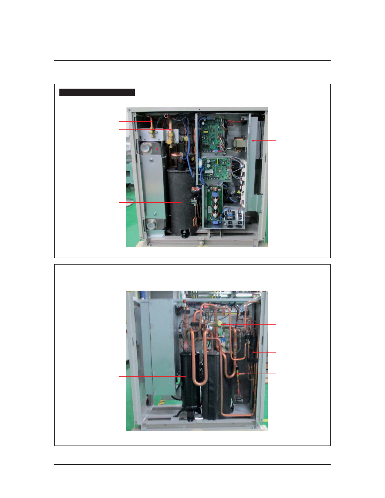
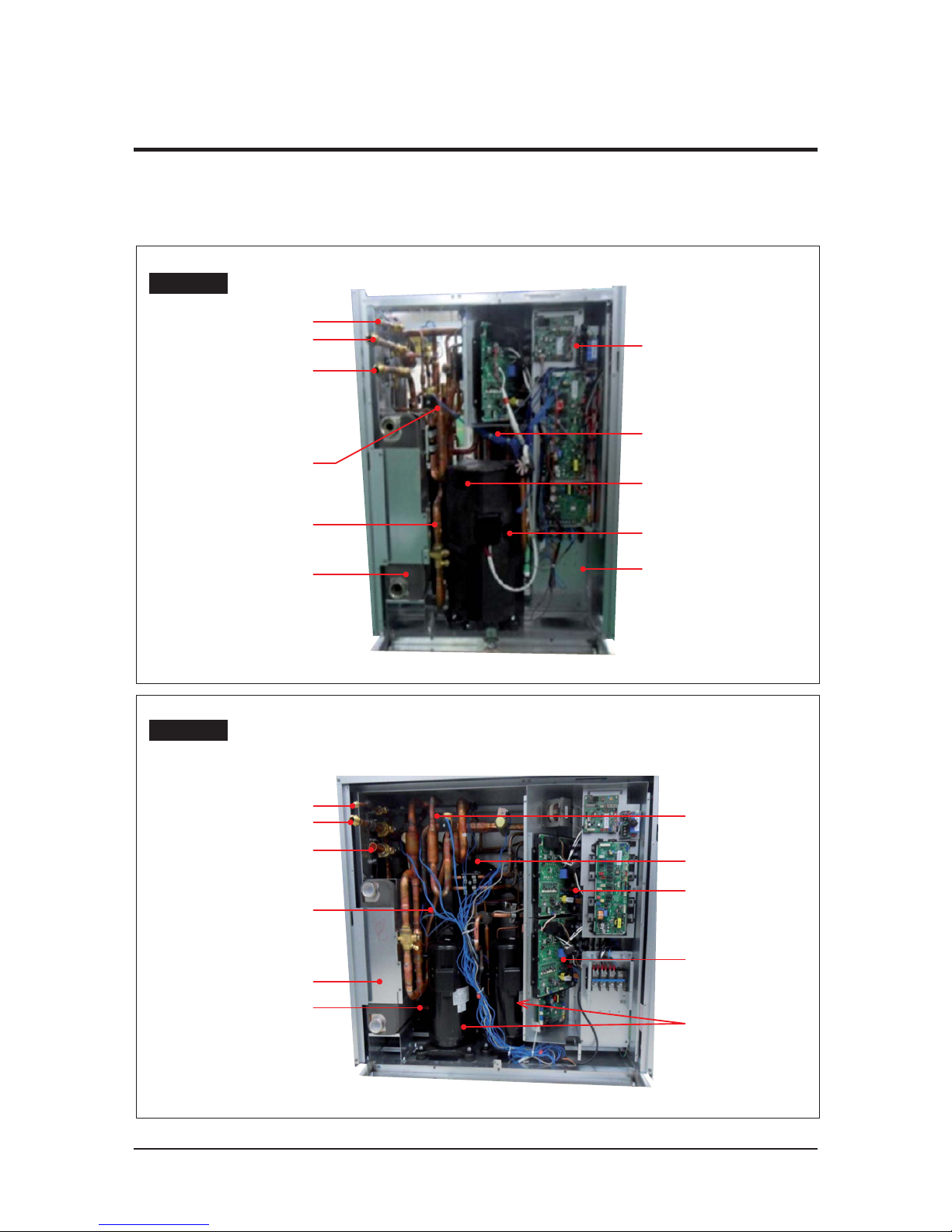
2-1-4 Structure of product
(Small size : AM080/100FXWANR* / AM072/096/120HXWAFR*
(Large size : AM200FXWANR*,AM300KXWANR* / AM192HXWAFR*,AM240KXWAFR*)
Small size
CONTROL BOX
Liquid Pipe
High pressure Gas Pipe
Low pressure Gas Pipe
4 WAY V/V
Receiver
Plate Heat Exchanger
Accumulator
Sub Cooler
Compressor
Oil separator
Large size
Liquid Pipe
4 WAY V/V
Accumulator
CONTROL BOX
Oil separator
Compressor
High pressure Gas Pipe
Low pressure Gas Pipe
Sub Cooler
Plate Heat Exchanger
Receiver
2-1 Feature of Product (cont.)

Samsung Electronics 12
Product Specifications
2-1-5 Structure of product
(Power supply for 460V, 60Hz, 3Φ : AM072/096/120/192/240*XWAJR Series)
2-1 Feature of Product (cont.)
Small size
CONTROL BOX
Liquid Pipe
High pressure Gas Pipe
Low pressure Gas Pipe
4 WAY V/V
Receiver
Plate Heat Exchanger
Accumulator
Sub Cooler
Compressor
Oil separator
TRANS BOX
Large size
TRANS BOX
Liquid Pipe
4 WAY V/V
Accumulator
CONTROL BOX
Oil separator
Compressor
High pressure
Gas Pipe
Low pressure
Gas Pipe
Sub Cooler
Plate Heat
Exchanger
Receiver
Product Specifications
Samsung Electronics 13
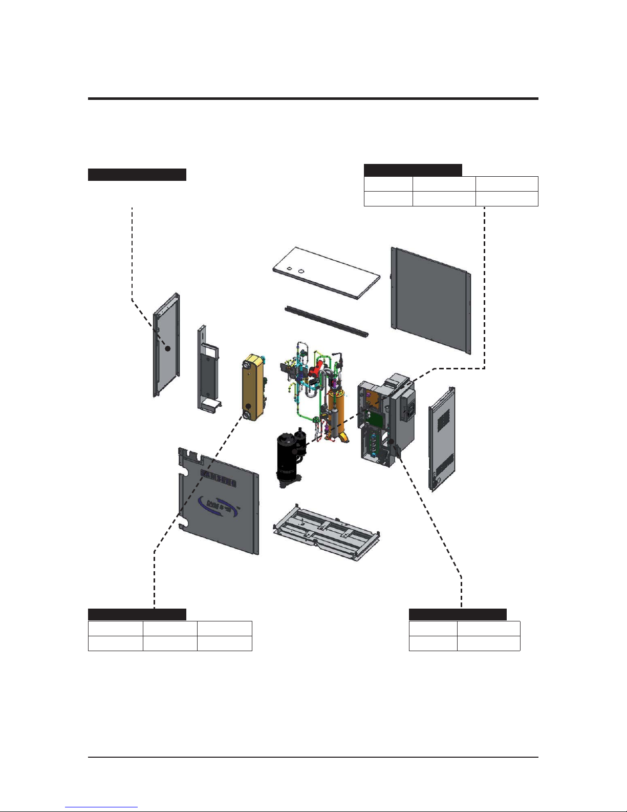
غ 3~6HP DVM S Water : Exploded View
- AM038/048/055KXWD***
2-1 Feature of Product (cont.)
ASSY CABINET PARTS
ل DVM WATER SMALL FRAME
- SIZE : (750 X 800 X 330)
ASSY COND PARTS
Model 038 048/055
DVM WATER CBH60-24H CBH60-34H
ASSY COMP PARTS
Model 038 048/055
DVM WATER UG8T300FUBJSG UG5T450FUEJXSG
ASSY CONTROL OUT
Model 038/048/055
DVM WATER 20A
Samsung Electronics 14
Product Specifications
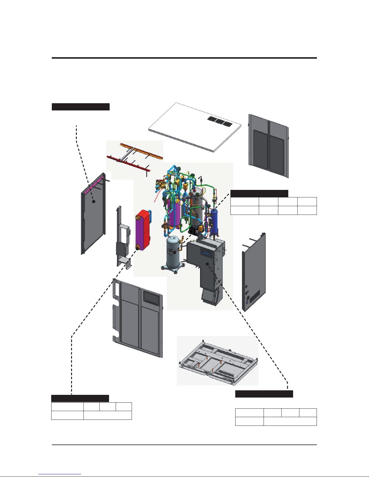
غ 8~12HP DVM S Water : Exploded View
- AM080/100/120FXWA***
- AM072/096/120HXWA***
2-1 Feature of Product (cont.)
ASSY CABINET PARTS
ل DVM WATER SMALL FRAME
- SIZE : (770 X 1000 X 545)
ASSY COND PARTS
Model 8HP 10HP 12HP
DVM WATER CBH60-54H
ASSY COMP PARTS
Model 8HP 10HP 12HP
DVM WATER 52CC*1 52CC*1 66CC*1
ASSY CONTROL OUT
Model 8HP 10HP 12HP
DVM WATER 35A
ل Refrigerant cooling system for IPM
Product Specifications
Samsung Electronics 15
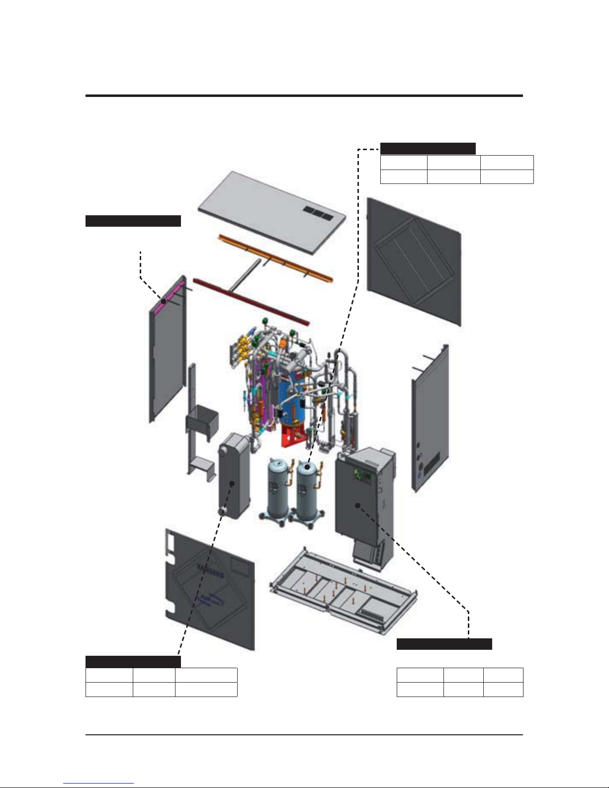
غ 20/30HP DVM S Water : Exploded View
- AM200/300*XWA***
- AM192/240*XWA***
2-1 Feature of Product (cont.)
ASSY CABINET PARTS
ل DVM WATER LARGE FRAME
- SIZE : ( 1100 x 1000 x 545 )
ASSY COMP PARTS
Model 20HP 30HP
DVM WATER 52CC*2 70CC*2
ASSY COND PARTS
Model 20HP 30HP
DVM WATER CBH60-88H ACH220EQ-70M
ASSY CONTROL OUT
Model 20HP 30HP
DVM WATER 35A*2 50A*2
ل Refrigerant cooling system for IPM
Samsung Electronics 16
Product Specifications
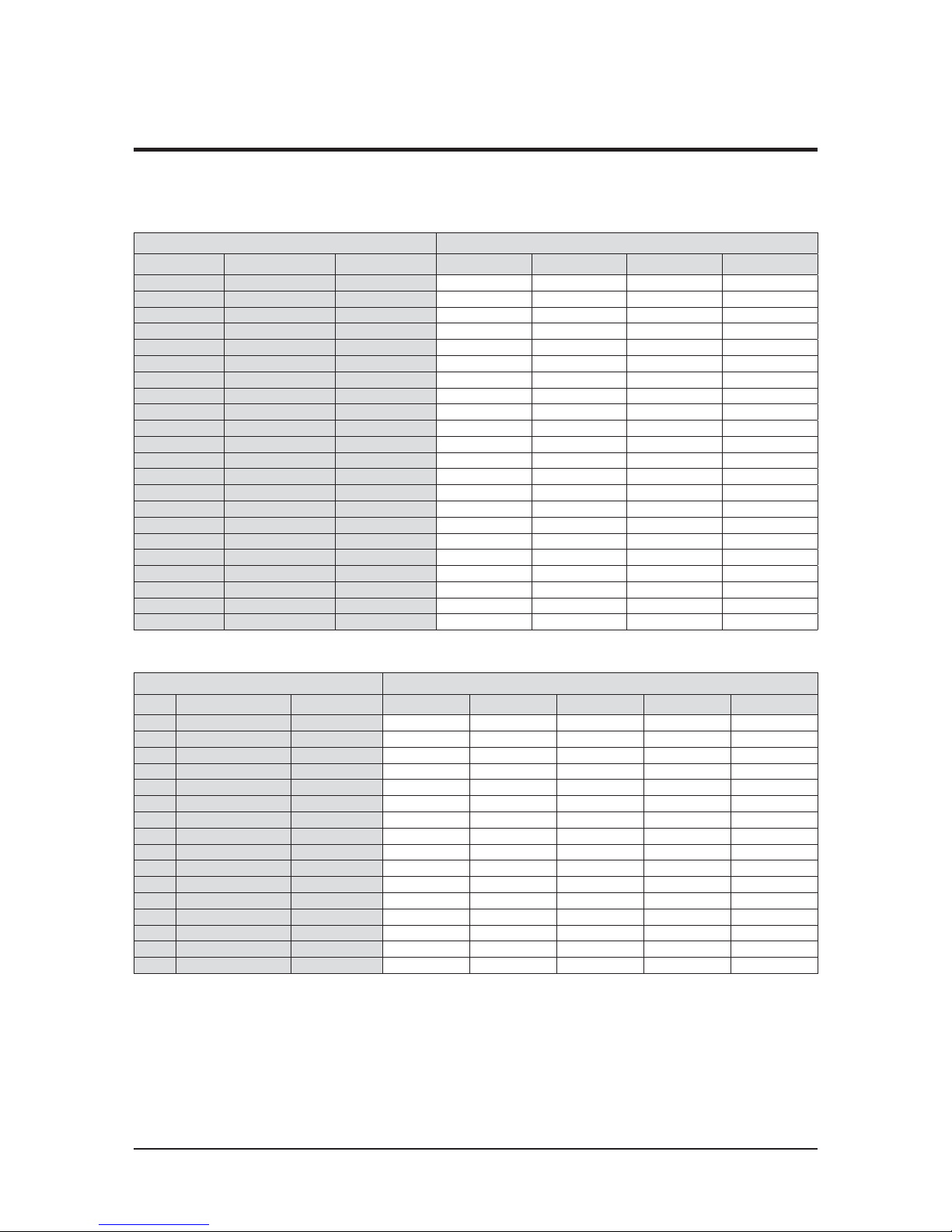
System Model
Capacity of Single Unit (HP)
Capa Code
No. of Modules
8HP 10HP 12HP 20HP
8 AM080FXWANR 1 1
10 AM100FXWANR 1 1
12 AM120FXWANR 1 1
16 AM160FXWANR2 2
2
18 AM180FXWANR2 2 1 1
20 AM200FXWANR 1 1
22 AM220FXWANR2 2
1
1
24 AM240FXWANR2 2
2
26 AM260FXWANR2 3 2 1
28 AM280FXWANR2 2
1
1
30 AM300FXWANR2 2
1
1
32 AM320FXWANR2 2 1
1
34 AM340FXWANR2 3 1 2
36 AM360FXWANR2 3 2 1
38 AM380FXWANR2 3
11
1
40 AM400FXWANR2 2
2
42 AM420FXWANR2 3
111
44 AM440FXWANR2 3
21
48 AM480FXWANR2 3
1
2
50 AM500FXWANR2 3
12
52 AM520FXWANR2 3
12
60 AM600FXWANR2 3
3
ሪ
Make sure to use an indoor unit that is compatible with DVM S Water-GEO.
ሪ
Indoor units can be connected within the range indicated in following table.
ሪ
If the total capacity of the connected indoor units exceeds the indicated maximum capacity, cooling and heating capacity of the
indoor unit may decrease.
ሪ
Total capacity of the connected indoor units can be allowed from 50% to 130% of the total outdoor unit capacity.
0.5 × Σ( Outdoor unit capacity) ≤ Total capacity of the connected indoor units ≤ 1.3 × Σ( Outdoor unit capacity)
ఐ
You can connect maximum 64 indoor units to the outdoor unit. Maximum quantity of connectable indoor unit is set to 64 since outdoor
unit only support up to 64 communication address. Indoor unit address can be assigned from 0~63.
If the indoor unit address was assigned from 64~79, E201 error will occur.
ఐ
Maximum 32 Wall-mount type indoor units with EEV (AM****NQDEH*, AM***JNV*) can be connected.
2-2 Model names of Indoor/Outdoor Unit
2-2-1 Outdoor unit combination
غ Premium Energy Efficiency Type (AM***FXWANR*)
غ Premium compact type (AM***KXWANR*)
System Model
Capacity of Single Unit (HP)
Capa Code
No. of Modules
8HP 10HP 12HP 20HP 30HP
30 AM300KXWANR 1
1
38 AM380KXWANR1 2 1
1
40 AM400KXWANR1 2 1
1
42 AM420KXWANR1 2 1 1
46 AM460KXWANR1 3 2 1
48 AM480KXWANR1 3
11
1
50 AM500KXWANR1 2 1 1
52 AM520KXWANR1
3
1
11
54 AM540KXWANR1
321
58 AM580KXWANR1
3
111
60 AM600KXWANR1
2 2
62 AM620KXWANR1
3
1
11
68 AM680KXWANR1
3
1
2
70 AM700KXWANR1
3
1
2
80 AM800KXWANR1
312
90 AM900KXWANR1 3
3
Product Specifications
Samsung Electronics 17
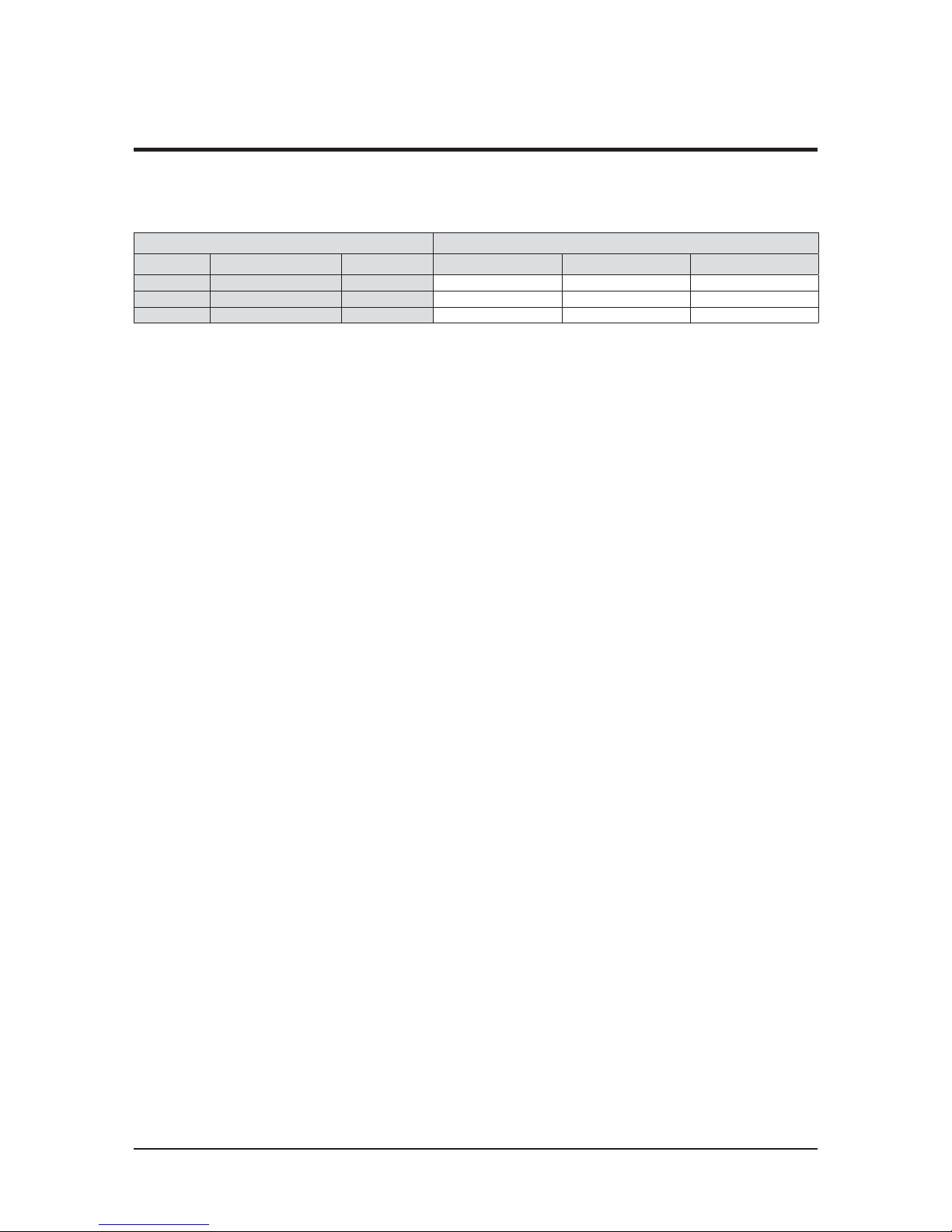
غ Premium Energy Efficiency Type (AM***KXWDCH*)
System Model Capacity of Single Unit (Ton)
Capa(ton) Code No. of Modules 3 4 5
3 AM038KXWDCH* 1 1
4 AM048KXWDCH* 1 1
5 AM055KXWDCH* 1 1
ሪ
Make sure to use an indoor unit that is compatible with DVM S Water-GEO.
ሪ
Indoor units can be connected within the range indicated in following table.
ሪ
If the total capacity of the connected indoor units exceeds the indicated maximum capacity, cooling and heating capacity of
the indoor unit may decrease.
ሪ
Total capacity of the connected indoor units can be allowed from 50% to 130% of the total outdoor unit capacity.
0.5 × Σ( Outdoor unit capacity) ≤ Total capacity of the connected indoor units ≤ 1.3 × Σ( Outdoor unit capacity)
ఐ
You can connect maximum 64 indoor units to the outdoor unit. Maximum quantity of connectable indoor unit is set to 64 since outdoor
unit only support up to 64 communication address. Indoor unit address can be assigned from 0~63. If the indoor unit address was assigned
from 64~79, E201 error will occur.
ఐ
Maximum 32 Wall-mount type indoor units with EEV (AM****NQDEH*, AM***JNV*) can be connected.
2-2 Model names of Indoor/Outdoor Unit (cont.)
2-2-1 Outdoor unit combination (cont.)

Samsung Electronics 18
Product Specifications
غ Premium Energy Efficiency Type (AM***HXWAF(J)R*)
غ Premium compact type (AM***KXWAF(J)R*)
System Model Capacity of Single Unit (Ton)
Capa(ton) Code No. of Modules 6 8 10 16
6 AM072HXWA*R 1 1
8AM096HXWA*R 1 1
10 AM120HXWA*R 1 1
12 AM144HXWA*R2 2
2
14 AM168HXWA*R2 2 1 1
16 AM192HXWA*R 1 1
18 AM216HXWA*R2 2
1
1
20 AM240HXWA*R2 2
2
22 AM264HXWA*R2 2 1
1
24 AM288HXWA*R2 2
1
1
26 AM312HXWA*R2 2 1 1
28 AM336HXWA*R2 3 2
1
30 AM360HXWA*R2 3 1 1
1
32 AM384HXWA*R2 2 2
34 AM408HXWA*R2 3
11
1
36 AM432HXWA*R2 3
21
38 AM456HXWA*R2 3
12
40 AM480HXWA*R2 3
12
42 AM504HXWA*R2 3
1
2
48 AM576HXWA*R2 3
3
System Model Capacity of Single Unit (Ton)
Capa(ton) Code No. of Modules 6 8 10 16 20
20 AM240KXWA*R 1 1
26 AM312KXWA*R1 2 1 1
28 AM336KXWA*R1 2 1 1
30 AM360KXWA*R1 2 1 1
34 AM408KXWA*R1 3 1 1 1
36 AM432KXWA*R1 3
1
11
38 AM456KXWA*R1 3 1 1 1
40 AM480KXWA*R1 2
2
44 AM528KXWA*R1 3 1 1 1
46 AM552KXWA*R1 3 1 2
48 AM576KXWA*R1 3
1
2
50 AM600KXWA*R1 3 1 2
ሪ
Make sure to use an indoor unit that is compatible with DVM S Water-GEO.
ሪ
Indoor units can be connected within the range indicated in following table.
ሪ
If the total capacity of the connected indoor units exceeds the indicated maximum capacity, cooling and heating capacity of
the indoor unit may decrease.
ሪ
Total capacity of the connected indoor units can be allowed from 50% to 130% of the total outdoor unit capacity.
0.5 × Σ( Outdoor unit capacity) ≤ Total capacity of the connected indoor units ≤ 1.3 × Σ( Outdoor unit capacity)
ఐ
You can connect maximum 64 indoor units to the outdoor unit. Maximum quantity of connectable indoor unit is set to 64 since outdoor
unit only support up to 64 communication address. Indoor unit address can be assigned from 0~63. If the indoor unit address was assigned
from 64~79, E201 error will occur.
ఐ
Maximum 32 Wall-mount type indoor units with EEV (AM****NQDEH*, AM***JNV*) can be connected.
2-2 Model names of Indoor/Outdoor Unit (cont.)
2-2-1 Outdoor unit combination (cont.)

Product Specifications
Samsung Electronics 19
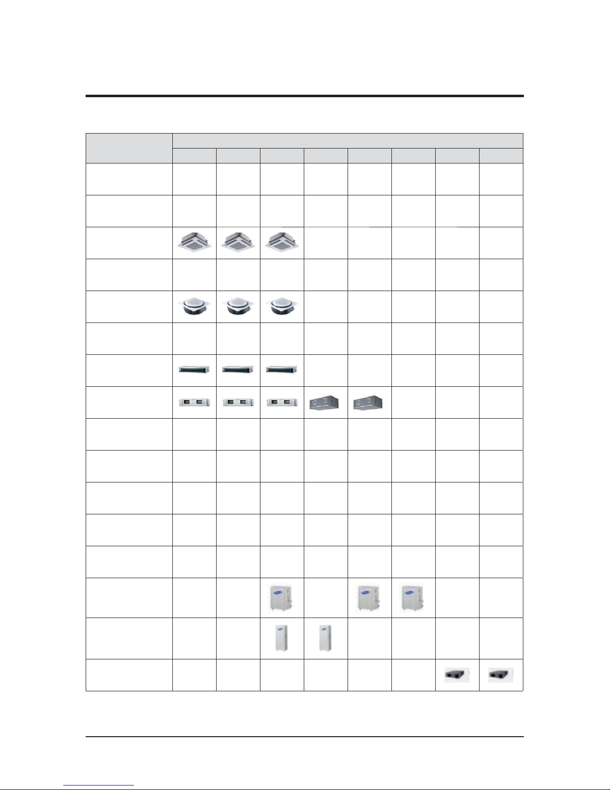
2-2-2 Indoor unit
2-2 Model names of Indoor/Outdoor Unit (cont.)
Model
Capacity ( kW )
1.7
2.2
2.8 3.6 4.5 5.6 6.0 7.1 9.0
Slim 1way cassette
(JSF)
2way cassette
Global 4way cas-
sette
4way CST
(600 X 600)
360 CST
Floor Standing
Unit
Slim duct
MSP duct
HSP duct
Ceiling
Console
Neo forte
Neo forte (with
EEV)
Hydro unit / HE
Hydro unit / HT
ERV plus
Samsung Electronics 20
Product Specifications
2-2-2 Indoor unit (cont.)
2-2 Model names of Indoor/Outdoor Unit (cont.)
Model
Capacity ( kW )
11.2 12.8 14.0 22.0 28.0 44.8 500CMH 1000CMH
Slim 1way cassette
(JSF)
2way cassette
Global 4way cassette
4way CST
(600 X 600)
360 CST
Floor Standing Unit
Slim duct
MSP duct
HSP duct
Ceiling
Console
Neo forte
Neo forte (with EEV)
Hydro unit / HE
Hydro unit / HT
ERV plus
Product Specifications
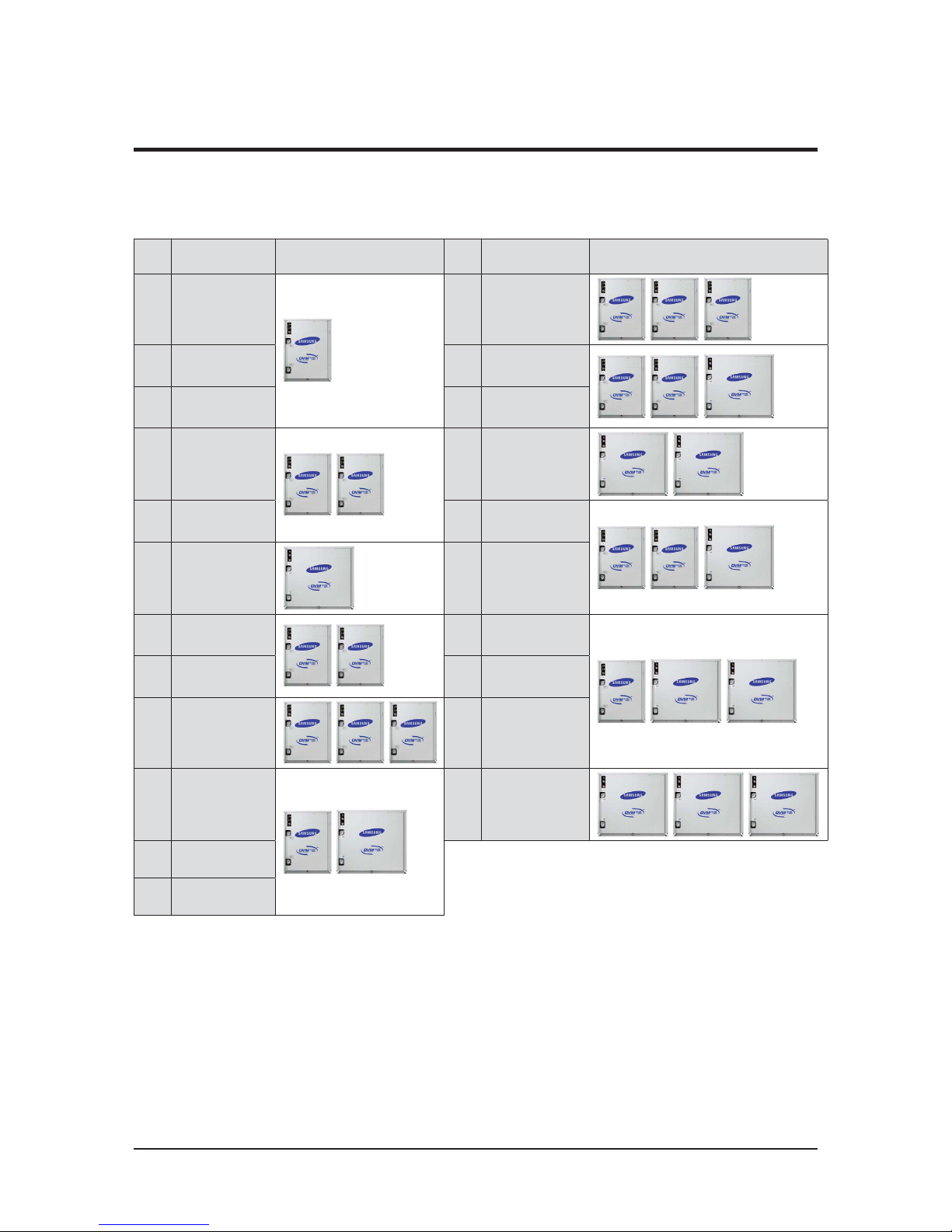
Samsung Electronics 21Samsung Electronics 21
Capa
[HP]
Model Name Model
Capa
[HP]
Model Name Model
8 AM080FXWANR 34 AM340FXWANR2
10 AM100FXWANR 36 AM360FXWANR2
12 AM120FXWANR 38 AM380FXWANR2
16 AM160FXWANR2
40 AM400FXWANR2
18 AM180FXWANR2 42 AM420FXWANR2
20 AM200FXWANR 44 AM440FXWANR2
22 AM220FXWANR2
48 AM480FXWANR2
24 AM240FXWANR2 50 AM500FXWANR2
26 AM260FXWANR2
52 AM520FXWANR2
28 AM280FXWANR2
60 AM600FXWANR2
30 AM300FXWANR2
32 AM320FXWANR2
غ Premium Energy Efficiency Type (AM***FXWANR*)
2-2 Model names of Indoor/Outdoor Unit (cont.)
2-2-3 Outdoor unit
Samsung Electronics 22
Product Specifications
Samsung Electronics 22
غ Premium Compact Type (AM***KXWANR*)
2-2 Model names of Indoor/Outdoor Unit (cont.)
2-2-3 Outdoor unit (cont.)
Capa
[HP]
Model Name Model
Capa
[HP]
Model Name Model
30 AM300KXWANR 58 AM580KXWANR1
38 AM380KXWANR1
60 AM600KXWANR1
40 AM400KXWANR1 62 AM620KXWANR1
42 AM420KXWANR1 68 AM680KXWANR1
46 AM460KXWANR1
70 AM700KXWANR1
48 AM480KXWANR1 80 AM800KXWANR1
50 AM500KXWANR1
90 AM900KXWANR1
52 AM520KXWANR1
54 AM540KXWANR1

Product Specifications
Samsung Electronics 23Samsung Electronics 23
غ Premium Energy Efficiency Type (AM***KXWDCH*)
غ Premium Energy Efficiency Type (AM***HXWAF(J)R*)
2-2 Model names of Indoor/Outdoor Unit (cont.)
2-2-3 Outdoor unit (cont.)
Capa
(Ton)
Model Name Model
Capa
[Ton]
Model Name Model
6 AM072HXWA*R 28 AM336HXWA*R2
8AM096HXWA*R 30 AM360HXWA*R2
10 AM120HXWA*R
32 AM384HXWA*R2
12 AM144HXWA*R2
34 AM408HXWA*R2
14 AM168HXWA*R2 36 AM432HXWA*R2
16 AM192HXWA*R
38 AM456HXWA*R2
18 AM216HXWA*R2
40 AM480HXWA*R2
20 AM240HXWA*R2 42 AM504HXWA*R2
22 AM264HXWA*R2
48 AM576HXWA*R2
24 AM288HXWA*R2
26 AM312HXWA*R2
Capa
(Ton)
Model Name Model
3 AM038KXWDCH*
4 AM048KXWDCH*
5 AM055KXWDCH*
Samsung Electronics 24
Product Specifications
Samsung Electronics 24
غ Premium compact type (AM***KXWAF(J)R*)
2-2 Model names of Indoor/Outdoor Unit (cont.)
2-2-3 Outdoor unit (cont.)
Capa
(Ton)
Model Name Model
Capa
[Ton]
Model Name Model
20 AM240KXWA*R 40 AM480KXWA*R1
26 AM312KXWA*R1
44 AM528KXWA*R1
28 AM336KXWA*R1 46 AM552KXWA*R1
30 AM360KXWA*R1 48 AM576KXWA*R1
34 AM408KXWA*R1
50 AM600KXWA*R1
36 AM432KXWA*R1
38 AM456KXWA*R1
Product Specifications
Samsung Electronics 25
2-3 Combination and Connection Ratio limitation
Indoor Units Installation and use limitations
Combination
Normal
Units
Hydro OAP AHU
Max. number of
indoor units for
connection
Combination
ratio
Other
limitations
Piping
limitations
DVM S Water O O 64 50~130%
Level difference
ODU-IDU
Outdoor unit in highest position
: 50m/40m
ఐ over 50m, install PDM kit
Indoor unit in highest position
: 50m
ఐ over 40m, contact local
dealer
IND-IND : 50m
(DVMs Heat pump)
IND-IND : 15m
(HR & Water)
ఐWall mounted with
EEV : 15m
Piping length from the first
branch pipe until the indoor unit
: 45m
ఐ If the condition
is satisfied : 90m
Long piping (equivalent length)
: 170m
Total piping length : 500m
DVM S Water O
64 50~130%
DVM S
Water+Hydro
(HP only)
O O 64 50~180%
Hydro units are applicable to heating only
(including floor heating).
Other common indoor
units are applicable to cooling onlyCombination ratio for
cooling-only indoor units
must be 100% or lower- It
is not possible to operate common indoor units
and hydro units simultaneously
DVM S
Water+OAP
(HP only)
O O O 64 50~100%
OAP must be lower than
30% of outdoor unit
capacity
DVM S
Water+OAP
(HP only)
O 64 50~100%
DVM S
Water+AHU
O 64 50~130%
DVM S
Water+AHU
O O O 64 50~130%
AHU must be lower than
50% of outdoor unit
capacity
DVM S Water+
(AHU+OAP)
(HP only)
O O O O 64 50~100%
OAP must be lower than
30% of outdoor unit
capacity- AHU+OAP
must be lower than 50%
of outdoor unit capacity
ఐ Normal Units : Cassette, Duct, Ceiling, Console, Wall Mounted, ERV+, Floor stand.
ఐ For wall mounted with EEV, it is possible to install a maximum of 32 units
ఐ ERV (not ERV+ ) can be installed separately without the need to lay refrigerant pipe.
 Loading...