

Samsung AM036JNCDCH, AM048JNCDCH Installation Manual

Contents
Safety precautions ................................................................................................................ 2
Selecting the installation location .................................................................................................4
Ceiling installation ................................................................................................................6
Purging the unit...................................................................................................................7
Connecting the refrigerant pipe . . . . . . . . . . . . . . . . . . . . . . . . . . . . . . . . . . . . . . . . . . . . . . . . . . . . . . . . . . . . . . . . . . . . . . . . . . . . . . . . . . . . . . . . . . . . . . . . . . . 7
Cutting/Flaring the pipes..........................................................................................................8
Performing leak test & insulation ..................................................................................................9
Drain hose installation ...........................................................................................................11
Wiring work......................................................................................................................12
Interface module Installation (Optional) ..........................................................................................15
Setting an indoor unit address and installation option ............................................................................16
Troubleshooting .................................................................................................................28
Safety precautions
Carefully follow the precautions listed below because they are essential to guarantee the safety of the equipment.
t Always disconnect the air conditioner from the power supply before servicing it or accessing its
WARNING
General information
f Carefully read the content of this manual before installing the air conditioner and store the manual in a safe place in order to be able to
use it as reference after installation.
f For maximum safety, installers should always carefully read the following warnings.
f Store the operation and installation manual in a safe location and remember to hand it over to the new owner if the air conditioner is
sold or transferred.
f This manual explains how to install an indoor unit with a split system with two SAMSUNG units. The use of other types of units with
dierent control systems may damage the units and invalidate the warranty. The manufacturer shall not be responsible for damages
arising from the use of non compliant units.
f This product has been determined to be in compliance with the Low Voltage Directive (2006/95/EC), the Electromagnetic
Compatibility Directive (2004/108/EC) and the Machinery Directive (2006/42/EC) of the European Union.
f The manufacturer shall not be responsible for damage originating from unauthorized changes or the improper connection of electric
and requirements set forth in the “Operating limits” table, included in the manual, shall immediately invalidate the warranty.
f The air conditioner should be used only for the applications for which it has been designed: the indoor unit is not suitable to be
installed in areas used for laundry.
f Do not use the units if damaged. If problems occur, switch the unit o and disconnect it from the power supply.
f In order to prevent electric shocks, res or injuries, always stop the unit, disable the protection switch and contact SAMSUNG’s technical
support if the unit produces smoke, if the power cable is hot or damaged or if the unit is very noisy.
f Always remember to inspect the unit, electric connections, refrigerant tubes and protections regularly. These operations should be
performed by qualied personnel only.
f The unit contains moving parts, which should always be kept out of the reach of children.
f Do not attempt to repair, move, alter or reinstall the unit. If performed by unauthorized personnel, these operations may cause electric
shocks or res.
f Do not place containers with liquids or other objects on the unit.
f All the materials used for the manufacture and packaging of the air conditioner are recyclable.
f The packing material and exhaust batteries of the remote controller(optional) must be disposed of in accordance with current laws.
f The air conditioner contains a refrigerant that has to be disposed of as special waste. At the end of its life cycle, the air conditioner must
be disposed of in authorized centers or returned to the retailer so that it can be disposed of correctly and safely.
internal components.
t Verify that installation and testing operations are performed by qualied personnel.
t Verify that the air conditioner is not installed in an easily accessible area.
2
Installing the unit
IMPORTANT: When installing the unit, always remember to connect rst the refrigerant tubes, then the electrical lines.
Always disassemble the electric lines before the refrigerant tubes.
f Upon receipt, inspect the product to verify that it has not been damaged during transport. If the product appears damaged, DO NOT
INSTALL it and immediately report the damage to the carrier or retailer (if the installer or the authorized technician has collected the
material from the retailer.)
f After completing the installation, always carry out a functional test and provide the instructions on how to operate the air conditioner
to the user.
f Do not use the air conditioner in environments with hazardous substances or close to equipment that release free ames to avoid the
occurrence of res, explosions or injuries.
f Our units should be installed in compliance with the spaces shown in the installation manual, to ensure accessibility from both sides
and allow repairs or maintenance operations to be carried out. The unit’s components should be accessible and easy to disassemble
without endangering people and objects.
For this reason, when provisions of the installation manual are not complied with, the cost required to access and repair the
units (in SAFETY CONDITIONS, as set out in prevailing regulations) with harnesses, ladders, scaolding or any other elevation
system will NOT be considered part of the warranty and will be charged to the end customer.
Power supply line, fuse or circuit breaker
f Always make sure that the power supply is compliant with current safety standards. Always install the air conditioner in compliance
with current local safety standards.
f Always verify that a suitable grounding connection is available.
f Verify that the voltage and frequency of the power supply comply with the specications and that the installed power is sucient to
ensure the operation of any other domestic appliance connected to the same electric lines.
f Always verify that the cut-o and protection switches are suitably dimensioned.
f Verify that the air conditioner is connected to the power supply in accordance with the instructions provided in the wiring diagram
included in the manual.
f Always verify that electric connections (cable entry, section of leads, protections…) are compliant with the electric specications and
with the instructions provided in the wiring scheme. Always verify that all connections comply with the standards applicable to the
installation of air conditioners.
f Devices disconnected from the power supply should be completely disconnected in the condition of overvoltage category.
t Make sure that you earth the cables.
CAUTION
- Do not connect the earth wire to the gas pipe, water pipe, lighting rod or telephone wire. If earthing is not complete,
electric shock or re may occur.
t Install the circuit breaker.
- If the circuit breaker is not installed, electric shock or re may occur.
t Make sure that the condensed water dripping from the drain hose runs out properly and safely.
t Install the power cable and communication cable of the indoor and outdoor unit at least 1m away from the electric
appliance.
t Install the indoor unit away from lighting apparatus using the ballast.
- If you use the wireless remote controller, reception error may occur due to the ballast of the lighting apparatus.
t Do not install the air conditioner in following places.
- Place where there is mineral oil or arsenic acid. Resin parts ame and the accessories may drop or water may leak.
The capacity of the heat exchanger may reduce or the air conditioner may be out of order.
- The place where corrosive gas such as sulfurous acid gas generates from the vent pipe or air outlet.
t The copper pipe or connection pipe may corrode and refrigerant may leak.
- The place where there is a machine that generates electromagnetic waves. The air conditioner may not operate
normally due to control system.
- The place where there is a danger of existing combustible gas, carbon ber or ammable dust.
t The place where thinner or gasoline is handled. Gas may leak and it may cause re.
ENGLISH
3
Selecting the installation location
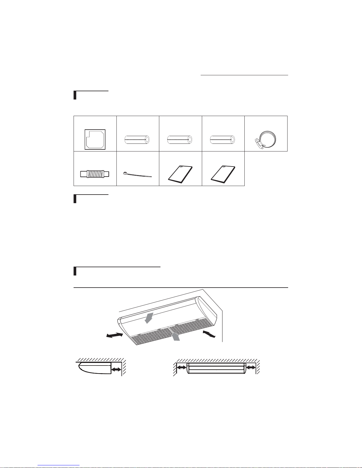
Accessories
f The following accessories are supplied with the indoor unit.
The type and quantity may dier depending on the specications.
Pattern sheet (2) Insulation cover pipe A (1) Insulation cover pipe B (1) Insulation drain (1) Flexible hose clamp (1)
Flexible hose (1) Cable-tie (8) User manual (1) Install manual (1)
Indoor Unit
f Select a convenient location that permits the air to reach every corner of the area to be cooled.
f Pre-plan for easy and short routing of the refrigerant tubing and wiring to the outdoor unit.
f There should be no ammable gas, alkaline, substances present in the air.
f Avoid location where obstacles preventing good air circulation are present.
f Noise prevention should be considered in determining the unit's location.
f The structure, where the unit is to be installed should be strong enough to support the weight of the unit.
f Rigid wall without vibration.
f Where it is not exposed to direct sunshine.
f Where the air lter can be removed and cleaned easily.
Space Requirements for Indoor Unit
Ceiling installation
11.81inch(300mm)
Ceiling Ceiling
Wall Wall
1.97inch(50mm)
4
1.97inch
(50mm)
11.81inch(300mm) or more
11.81inch(300mm) or more

Dimension of the indoor unit
Unit:Inch(mm)
“A”
“B”
ENGLISH
10.24”(260)
2.60”(66)
1.10”
(28)
1.65”
(42)
4.33”
(110)
4.92”
(125)
3.54”
3
1
2
Model
AM036JNCDCH
AM048JNCDCH
5.29”
(90)
26.57”(675)
(134.3)
6.14”(156)
9.25”(235)
3.94”(100)
Dimension
“A” “B ”
53.15"(1350) 51.10"(1298)
64.96"(1650) 62.91"(1598)
No. Name Description
1 Liquid pipe connection ø9.52 (3/8”)
2 Gas pipe connection ø15.88 (5/8”)
3 Drain pipe connection OD ø25(0.98"); ID ø020(0.79")
5
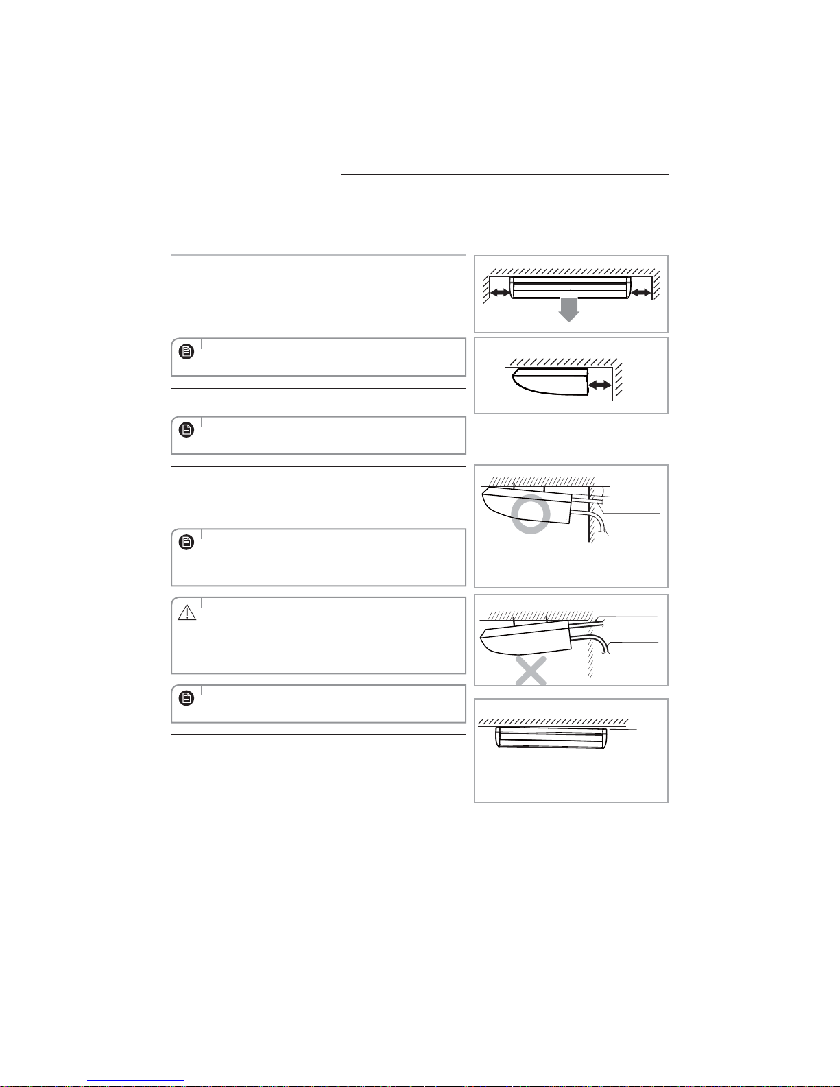
Ceiling installation
It is recommended to install the Y-joint before installing the indoor
unit.
1 Select pipe directions.
When the directions are selected, drill 3-1/8''-[3.94inch(100mm), for
pipe and cables] and 1-3/4''-[1.54inch(40mm), for drain hose] diameter
holes on the wall so that it slants slightly downwards toward the
outdoor for smooth water ow.
11.81inch(300mm )
or more
11.81inch(300mm )
or more
Use the template to select pipe directions.
NOTE
2 Drill holes for anchor bolts according to the distance and mount them.
Use the template.
NOTE
3 Install the unit onto the ceiling. Be sure to arrange the drain hose so
that it is leveled lower than the drain hose connecting port of the
indoor unit.
For proper drainage of condensate, give a 2° [The gap between
the lower end of the indoor unit and the ceiling should be
NOTE
0.91inch(23mm) or more.] slant to the side of the unit which will be
connected with the drain hose as shown in the gure.
t Ensure that the ceiling is strong enough to support the weight of
the indoor unit.
CAUTION
t Before hanging the unit, test the strength of each attached
suspension bolt.
t Install the drain hose from the rear of the unit.
Give a 1˚ slant to the right side of the unit.
NOTE
Ceiling
Wall
1.97inch(50mm)
❈ 2˚
Connection pipe
Drain hose
❈ 2˚ [The gap between the lower end of
the indoor unit and the ceiling should be
0.91inch(23mm) or more.]
Connection pipe
Drain hose
Wall
❈ 1˚
6
❈ The gap between the lower end of the
indoor unit and the ceiling should be 1˚ or
1.10inch(28mm).
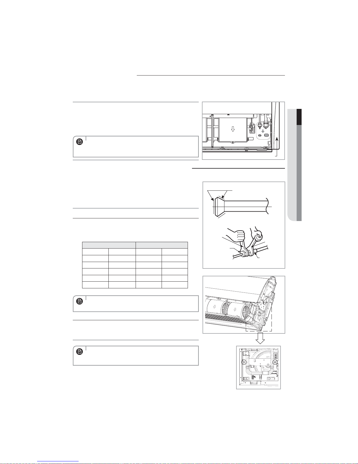
Purging the unit
On delivery, the indoor unit is loaded with inert Nitrogen gas. All this gas must therefore be purged before connecting
the assembly piping. To purge the inert gas, proceed as follows.
1 Unscrew the caps at the end of each pipe.
Result: All inert gas escapes from the indoor unit.
Loosen but do not remove completely the are nuts with plastic caps.
- You should hear gas escaping.
t To prevent dirt or foreign objects from getting into the pipes
during installation, do NOT remove the caps completely until you
NOTE
are ready to connect the piping.
Connecting the refrigerant pipe
There are two refrigerant pipes of differing diameters:
f A smaller one for the liquid refrigerant
f A larger one for the gas refrigerant
f The inside of copper pipe must be clean & has no dust.
1
Before connecting the refrigerant pipe, remove the side covers.
Remove the pinch pipe on the pipes and connect the assembly pipes
2
to each pipe, tightening the nuts, rst manually and then with a torque
wrench, a spanner applying the following torque.
Outer Diameter (D) Torque
mm inch /tN MCGtGU
ø 6.35 1/4 18 13.3
ø 9.52 3/8 42 31.0
ø 12.7 1/2 55 40.6
ø 15.88 5/8 65 47.9
ø 19.05 3/4 100 73.8
ENGLISH
Side cover
Refrigerant oil
Torque wrench
Spanner
Flare nut
Union
Must apply refrigerant oil on the aring area to prevent a leak.
NOTE
3 Be sure that there must be no crack or kink on the bended area.
If necessary, the right side hanging bracket can be removed to
aid installation, by removing two screws. Remember to ret the
NOTE
bracket.
7
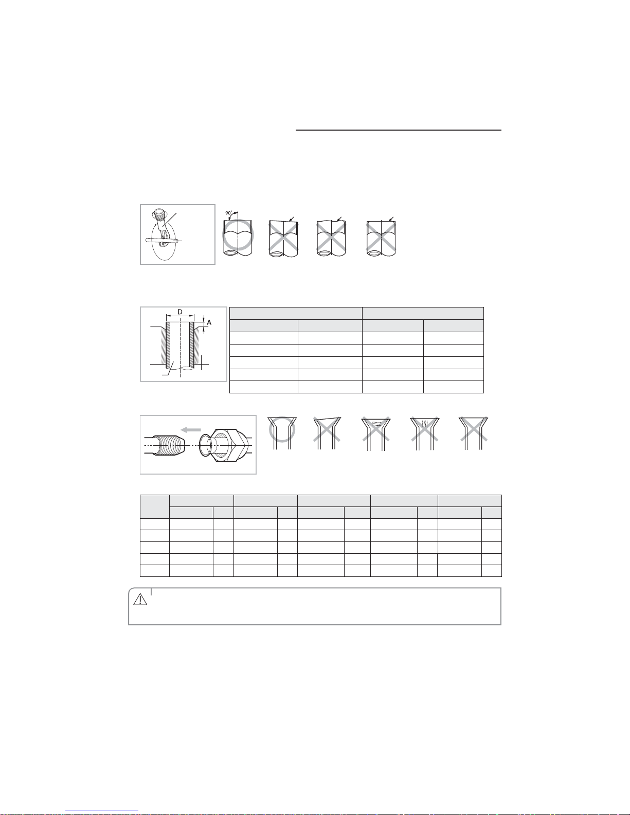
Cutting/Flaring the pipes
1. Make sure that you have the required tools available. (pipe cutter, reamer, aring tool and pipe holder)
2. If you wish to shorten the pipes, cut it with a pipe cutter, taking care to ensure that the cut edge remains at a 90° angle with the
side of the pipe. Refer to the illustrations below for examples of edges cut correctly and incorrectly.
Pipe cutter
Pipe
3. To prevent any gas from leaking out, remove all burrs at the cut edge of the pipe, using a reamer.
4. Slide a are nut on to the pipe and modify the are.
ø12.70 1/2 2.0 0.08
Pipe
Flare
ø15.88 5/8 2.2 0.09
ø19.05 3/4 2.2 0.09
5. Check that the aring is correct, referring to the illustrations below for examples of incorrect aring.
Oblique Rough
Outer Diameter (D) Depth (A)
mm inch mm inch
ø6.35 1/4 1.3 0.05
ø9.52 3/8 1.8 0.07
Burr
CrackedDamaged SurfaceInclinedCorrect
Uneven
Thickness
6. Align the pipes and tighten the are nuts rst manually and then with a torque wrench, applying the following torque.
Valve
1/4" 17 18 23 20 18 16~18 Allen(hex.) 5 9 - 0.34
3/8" 22 42 23 20 18 16~18 Allen(hex.) 5 9 - 0.34
1/2" 26 55 29 40 18 16~18 Allen(hex.) 5 13 - 0.34
5/8" 29 65 29 40 18 16~18 Allen(hex.) 5 13 - 0.34
3/4" 36 100 38 40 18 16~18 Allen(hex.) 5 13 - 0.34
Flare nut Valve cap Pressure port cap Valve needle Pressure port
Wrench(mm) /tN Wrench(mm) /tN Wrench(mm) /tN Wrench(mm) /tN Wrench(mm) /tN
t If the pipes require brazing, ensure that OFN (Oxygen Free Nitrogen) is owing through the system. If it is not
owing,Comp or valve can be damaged.
CAUTION
t Nitrogen blowing pressure range is 0.02 ~ 0.05MPa.
8
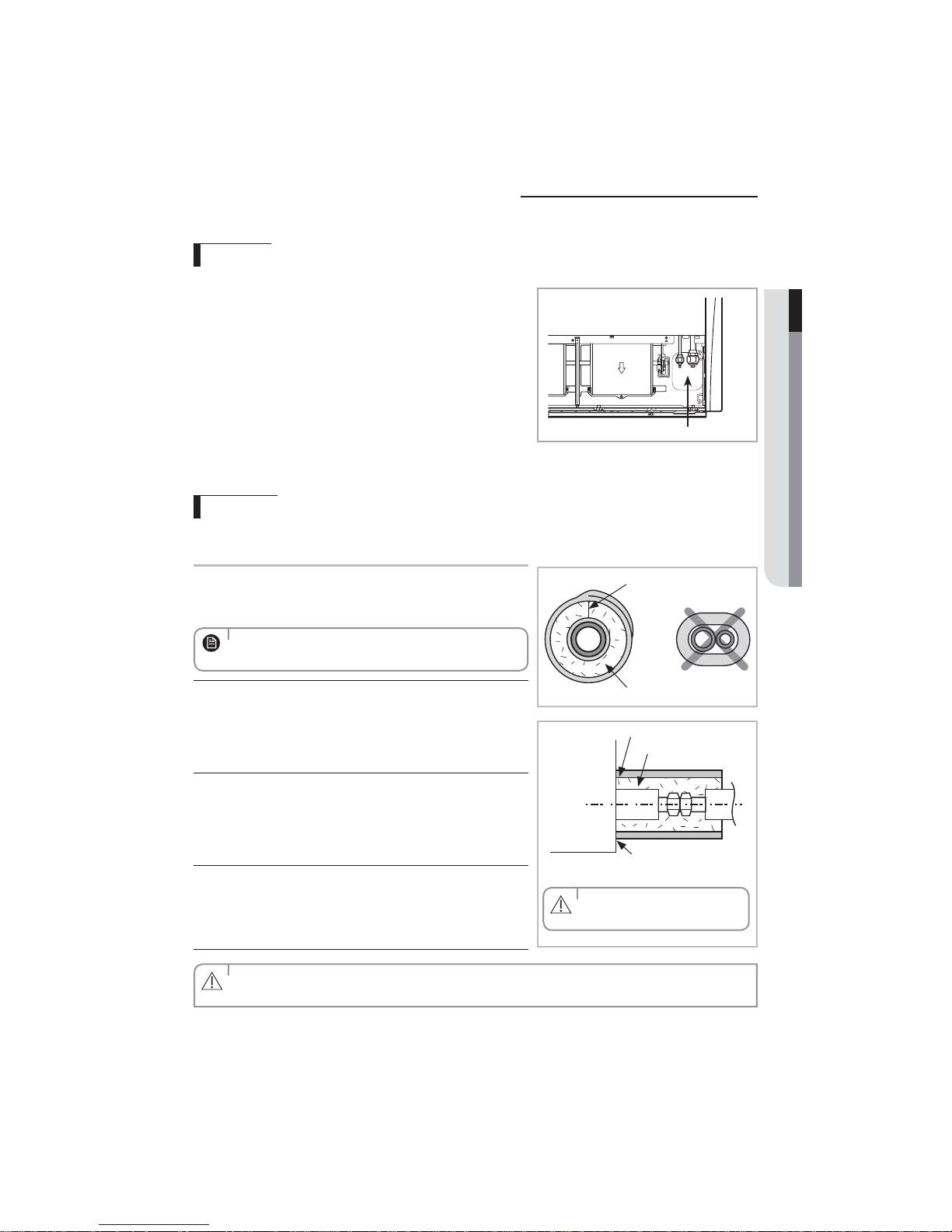
Performing leak test & insulation
Leak test
LEAK TEST WITH NITROGEN (before opening valves)
In order to detect basic refrigerant leaks, before recreating the
vacuum and recirculating the R-410A, it’s responsable of installer
to pressurize the whole system with nitrogen (using a cylinder
with pressure reducer) at a pressure above 40 bar (gauge).
LEAK TEST WITH R-410A (after opening valves)
Before opening valves, discharge all the nitrogen into the system
and create vacuum. After opening valves check leaks using a leak
detector for refrigerant R410A.
Insulation
Once you have checked that there are no leaks in the system, you
can insulate the piping and hose.
1
To avoid condensation problems, place Acrylonitrile Butadien Rubber
separately around each refrigerant pipe.
Always make the seam of pipes face upwards.
NOTE
ENGLISH
Leak check
❈ The designs and shape are subject to change
according to the model.
No gap
2
Wind insulating tape around the pipes and drain hose avoiding to
EPDM, NBR
compress the insulation too much.
Insulation cover pipe
Insulation pipe
3 Finish wrapping insulating tape around the rest of the pipes leading to
Indoor unit
the outdoor unit.
Be sure to overlap the
insulation
4 The pipes and electrical cables connecting the indoor unit with the
outdoor unit must be xed to the wall with suitable ducts.
All refrigerant connection must be accessible, in order to permit either unit maintenance or removing it completely.
CAUTION
Must t tightly against body
without any gap.
CAUTION
9
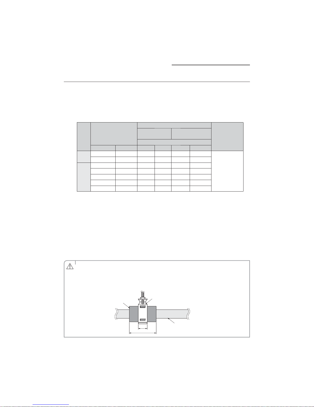
Performing leak test & insulation
5 Select the insulation of the refrigerant pipe.
f Insulate the gas side and liquid side pipe referring to the thickness according to the pipe size.
f Indoor temperature of
If installing in a high humidity condition, use one grade thicker insulator by referring to the table below.
If installing in an unfavorable conditions, use thicker one.
f Insulator’s heat-resistance temperature should be more than 120°C(248 °F).
Pipe
Liquid
pipe
Gas
pipe
f When installing insulation in places and conditions below, use the same insulation that is used for high humidity
conditions.
<Geological condition>
- High humidity places such as shoreline, hot spring, near lake or river, and ridge (when the part of the building is
covered by earth and sand.)
<Operation purpose condition>
- Restaurant ceiling, sauna, swimming pool etc.
<Building construction condition>
- The ceiling frequently exposed to moisture and cooling is not covered.
e.g. The pipe installed at a corridor of a dormitory and studio or near an exit that opens and closes frequently.
- The place where the pipe is installed is highly humid due to the lack of ventilation system.
30°C(86°F) and humidity of 85% is the standard condition.
Insulation Type (Heating/Cooling)
Pipe size
mm inch mm inch mm inch
6.35 ~ 9.52 1/4~3/8 9 3/8 9 3/8
12.7 ~ 19.05 1/2~3/4 13 1/2 13 1/2
6.35 1/4 13 1/2 19 3/4
9.52 3/8 19 3/4 25 1
12.7 1/2 19 3/4 25 1
15.88 5/8 19 3/4 25 1
19.05 3/4 19 3/4 25 1
General
[30°C(86°F), 85%]
High humidity
[30°C(86°F), over 85%]
EPDM,NBR
Remarks
Heating resisting
temperature over
120°C(248°F)
t Install the insulation not to get wider and use the adhesives on the connection part of it to prevent moisture from
entering.
CAUTION
t Wind the refrigerant pipe with insulation tape if it is exposed to outside sunlight.
t Install the refrigerant pipe respecting that the insulation does not get thinner on the bent part or hanger of pipe.
t Add the additional insulation if the insulation plate gets thinner.
Additional insulation
10
a× 3
Hanger
a
Insulated refrigerant pipe
 Loading...