

Samsung AM036FXMDCH, AM048FXMDCH, AM053FXMDCH, AM040TXMDEH, AM040TXMDGH Installation Manual
...
AM0@@FXMDCH_IM_EN_03408A(1).indd 50 2013-03-04 오후 4:28:30
This manual is made with 100% recycled paper.
DB68-03408A(1)
EN ES FR PT
AMFXMDCH Series
Air Conditioner
installation manual
imagine the possibilities
Thank you for purchasing this Samsung product.
To receive more complete service, please
register your product at
www.samsung.com/register
AM0@@FXMDCH_IM_EN_03408A(1).indd 51 2013-03-04 오후 4:28:30

2
Contents
Safety precautions . . .. . .. . .. . .. . .. . .. . .. . .. . . .. . .. . .. . .. . .. . .. . .. . .. . .. . .. . . .. . .. . .. . .. . .. . .. . .. . .. . .. . .. . . .. . .. . .. . .. . .. . . 3
Outdoor unit type . . .. . .. . .. . .. . . .. . .. . .. . .. . .. . .. . .. . .. . .. . .. . . .. . .. . .. . .. . .. . .. . .. . .. . .. . .. . . .. . .. . .. . .. . .. . .. . .. . .. . .. . . 5
Installation combination . . .. . .. . .. . .. . .. . .. . .. . .. . .. . .. . . .. . .. . .. . .. . .. . .. . .. . .. . .. . .. . . .. . .. . .. . .. . .. . .. . .. . .. . .. . .. . . .. . . 5
Deciding to where to install the outdoor unit .. . .. . .. . .. . .. . .. . .. . .. . .. . .. . . .. . .. . .. . .. . .. . .. . .. . .. . .. . .. . . .. . .. . .. . .. . .. . .. 6
Installation location . . .. . .. . .. . .. . .. . .. . .. . .. . .. . .. . . .. . .. . .. . .. . .. . .. . .. . .. . .. . .. . . .. . .. . .. . .. . .. . .. . .. . .. . .. . .. . . .. . .. . .. . 8
Installation and base ground work for an outdoor unit . . . .. . .. . .. . .. . .. . .. . .. . .. . .. . .. . . .. . .. . .. . .. . .. . .. . .. . .. . .. . .. . . .. . 10
Refrigerant pipe installation . .. . .. . .. . .. . . .. . .. . .. . .. . .. . .. . .. . .. . .. . .. . . .. . .. . .. . .. . .. . .. . .. . .. . .. . .. . . .. . .. . .. . .. . .. . .. . 12
Wiring work . .. . .. . . .. . .. . .. . .. . .. . .. . .. . .. . .. . .. . . .. . .. . .. . .. . .. . .. . .. . .. . .. . .. . . .. . .. . .. . .. . .. . .. . .. . .. . .. . .. . . .. . .. . .. . 31
Grounding work .. . .. . .. . .. . .. . .. . .. . . .. . .. . .. . .. . .. . .. . .. . .. . .. . .. . . .. . .. . .. . .. . .. . .. . .. . .. . .. . .. . . .. . .. . .. . .. . .. . .. . .. . . 36
Setting outdoor unit option switch and key function . . . . . . . . . . . . . . . . . . . . . . . . . . . . . . . . . . . . . . . . . . . . . . . . . . . . . . . . . . . . . . . . . . . . . . 37
Pump Down . . .. . .. . .. . .. . .. . .. . .. . .. . . .. . .. . .. . .. . .. . .. . .. . .. . .. . .. . . .. . .. . .. . .. . .. . .. . .. . .. . .. . .. . . .. . .. . .. . .. . .. . .. . .. . 42
Checking lists after finishing installation .. . .. . .. . .. . . .. . .. . .. . .. . .. . .. . .. . .. . .. . .. . . .. . .. . .. . .. . .. . .. . .. . .. . .. . .. . . .. . .. . . 44
Inspection and check operation .. . .. . . .. . .. . .. . .. . .. . .. . .. . .. . .. . .. . . .. . .. . .. . .. . .. . .. . .. . .. . .. . .. . . .. . .. . .. . .. . .. . .. . .. . . 45
Automatic refrigerant amount detection function (Checking th amount of refrigerant) . . .. . .. . .. . .. . .. . . .. . .. . .. . .. . .. . .. . 47
Trial operation . . .. . .. . .. . .. . .. . .. . .. . .. . .. . . .. . .. . .. . .. . .. . .. . .. . .. . .. . .. . . .. . .. . .. . .. . .. . .. . .. . .. . .. . .. . . .. . .. . .. . .. . .. . . 48
AM0@@FXMDCH_IM_EN_03408A(1).indd 2 2013-03-04 오후 4:28:13

3
ENGLISH
Safety precautions
Carefully follow the precautions listed below because they are essential to guarantee the safety of the equipment.
WARNING
• Always disconnect the air conditioner from the power supply before servicing it or
accessing its internal components.
• Verify that installation and testing operations are performed by qualified personnel.
• Verify that the air conditioner is not installed in an easily accessible area.
General information
Carefully read the content of this manual before installing the air conditioner and store the manual in a safe place in order
to be able to use it as reference after installation.
For maximum safety, installers should always carefully read the following warnings.
Store the operation and installation manual in a safe location and remember to hand it over to the new owner if the air
conditioner is sold or transferred.
This manual explains how to install an indoor unit with a split system with two SAMSUNG units. The use of other types
of units with different control systems may damage the units and invalidate the warranty. The manufacturer shall not be
responsible for damages arising from the use of non compliant units.
This product has been determined to be in compliance with the Low Voltage Directive (2006/95/EC), and the
Electromagnetic Compatibility Directive (2004/108/EC) of the European Union.
The manufacturer shall not be responsible for damage originating from unauthorized changes or the improper
connection of electric and requirements set forth in the “Operating limits” table, included in the manual. Making such
changes or improper connections may damage the units and invalidate the warranty.
The air conditioner should be used only for the applications for which it has been designed: the indoor unit is not suitable
to be installed in areas used for laundry.
Do not use the units if damaged. If problems occur, switch the unit off and disconnect it from the power supply.
In order to prevent electric shocks, fires or injuries, always stop the unit, disable the protection switch and contact
SAMSUNG’s technical support if the unit produces smoke, if the power cable is hot or damaged or if the unit is very noisy.
Always remember to inspect the unit, electric connections, refrigerant tubes and protections regularly. These operations
should be performed by qualified personnel only.
The unit contains moving parts, which should always be kept out of the reach of children.
Do not attempt to repair, move, alter or reinstall the unit. If performed by unauthorized personnel, these operations may
cause electric shocks or fires.
Do not place containers with liquids or other objects on the unit.
All the materials used for the manufacture and packaging of the air conditioner are recyclable.
The packing material and exhaust batteries of the remote controller(optional) must be disposed of in accordance with
current laws.
The air conditioner contains a refrigerant that has to be disposed of as special waste. At the end of its life cycle, the air
conditioner must be disposed of in authorized centers or returned to the retailer so that it can be disposed of correctly
and safely.
This appliance is not intended for use by persons (including children) with reduced physical, sensory or mental
capabilities, or lack of experience and knowledge, unless they have been given supervision or instruction concerning use
of the appliance by a person responsible for their safety. Children should be supervised to ensure that they do not play
with the appliance.
When the product operates in heat mode during winter time, it operates protection mode when the outdoor
temperature drops below 0°C(32°F). Therefore, supply the power during winter time. If the power is not supplied,
compressor protection mode will not operate and cause product malfunction.
AM0@@FXMDCH_IM_EN_03408A(1).indd 3 2013-03-04 오후 4:28:13

4
Safety precautions
Installing the unit
IMPORTANT: When installing the unit, always remember to connect first the refrigerant tubes, then the electrical lines. Always
disassemble the electric lines before the refrigerant tubes.
Upon receipt, inspect the product to verify that it has not been damaged during transport. If the product appears
damaged, DO NOT INSTALL it and immediately report the damage to the carrier or retailer (if the installer or the
authorized technician has collected the material from the retailer.)
After completing the installation, always carry out a functional test and provide the instructions on how to operate the air
conditioner to the user.
Do not use the air conditioner in environments with hazardous substances or close to equipment that release free flames
to avoid the occurrence of fires, explosions or injuries.
Our units should be installed in compliance with the spaces shown in the installation manual, to ensure accessibility from
both sides and allow repairs or maintenance operations to be carried out. The unit’s components should be accessible
and easy to disassemble without endangering people and objects.
For this reason, when provisions of the installation manual are not complied with, the cost required to access and repair
the units (in SAFETY CONDITIONS, as set out in prevailing regulations) with harnesses, ladders, scaffolding or any other
elevation system will NOT be considered part of the warranty and will be charged to the end customer.
Power supply line, fuse or circuit breaker
Always make sure that the power supply is compliant with current safety standards. Always install the air conditioner in
compliance with current local safety standards.
Always verify that a suitable grounding connection is available.
Verify that the voltage and frequency of the power supply comply with the specifications and that the installed power is
sufficient to ensure the operation of any other domestic appliance connected to the same electric lines.
Always verify that the cut-off and protection switches are suitably dimensioned.
Verify that the air conditioner is connected to the power supply in accordance with the instructions provided in the
wiring diagram included in the manual.
Always verify that electric connections (cable entry, section of leads, protections…) are compliant with the electric
specifications and with the instructions provided in the wiring scheme. Always verify that all connections comply with
the standards applicable to the installation of air conditioners.
Devices disconnected from the power supply should be completely disconnected in the condition of overvoltage
category.
AM0@@FXMDCH_IM_EN_03408A(1).indd 4 2013-03-04 오후 4:28:13

5
ENGLISH
Outdoor unit type
Shape
Model Cooling and Heating 1phase
AM036FXMDCH
AM048FXMDCH
AM053FXMDCH
Installation combination
You must install the indoor unit that uses R410A only.
If sum capacity of the combined indoor units exceeds the capacity of an outdoor unit, the capacity of each indoor unit is
reduced below the rated capacity. Therefore, keeping the combination of indoor units within the capacity of an outdoor
unit is recommended.
Outdoor unit
Outdoor unit capacity
[HP(Ton)]
The maximum number of
connectable indoor units
Total capacity of the
connected indoor units
[kW(MBH)]
AM036FXMDCH 4(3) 6 5.6~14.5(19~ 49)
AM048FXMDCH 5(4) 8 7.0~18.2(24~62)
AM053FXMDCH 6(5) 9 7.8~20.2(27~69)
AM0@@FXMDCH_IM_EN_03408A(1).indd 5 2013-03-04 오후 4:28:13
6
Deciding to where to install the outdoor unit
Decide the installation location based on the following condition and obtain the user’s approval.
Avoid a place that may disturb your neighbor. Noise may occur from the outdoor unit and the discharged air may run into
the neighborhood. (Be careful of the operation time in a residential area)
Install the outdoor unit on a hard and even area that can support its weight.
Choose a flat place where rainwater does not settle or leak.
Choose a place that will avoid strong winds.
Choose a place that is well ventilated and allows enough space for repairs and service.
(Discharge duct can be purchased privately.)
Choose a place where the connection of refrigerant pipe between an indoor unit and outdoor unit is within allowed
distance.
Make sure that the condensed water dripping from the drain hose runs out properly and safely.
Choose a place where flammable gas does not leak.
Choose a place where the unit could not come into contact with snow and rain.
When installing the outdoor unit near sea shore, make sure it is not directly exposed to sea breeze.
- When installing the outdoor unit near sea shore, consult the qualified installer since the places above require additional
measures for corrosion resistance. (You should remove salt and dust of a heat exchanger at least once a year.)
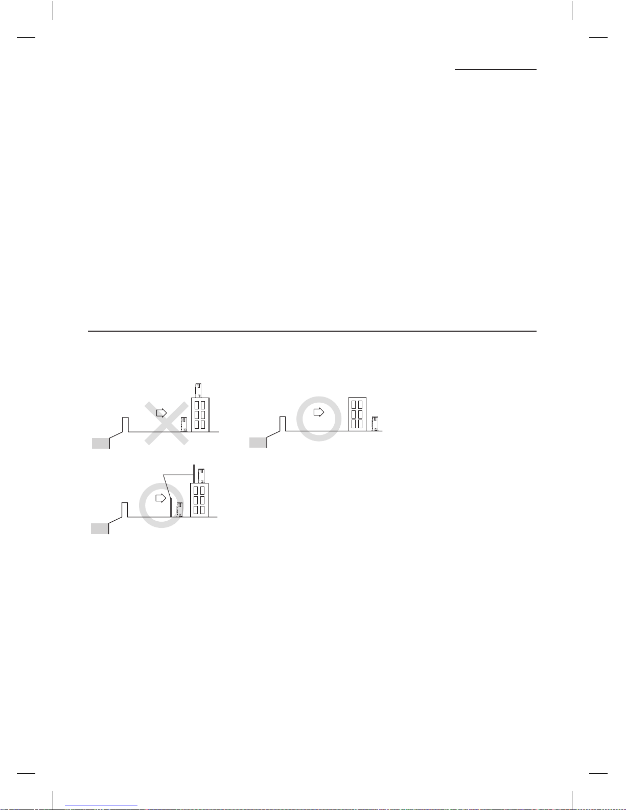
When installing an outdoor unit near sea shore
When installing an outdoor unit near sea shore, it should be placed behind a building or surrounded by wind protection
wall.
Install the outdoor unit in a place where water can drain smoothly.
Outdoor unit
Sea breeze
Sea
Outdoor unit
Sea breeze
Sea
Protection wall
Outdoor unit
Sea breeze
Sea
Protection wall should be constructed with a solid material such as concrete to block the sea breeze and the height and
the width of the wall should be 1.5 times larger than the size of the outdoor unit.
(Also, allow over 700mm (28 inch) space between the protection wall and the outdoor unit for ventilation of exhaust air.)
AM0@@FXMDCH_IM_EN_03408A(1).indd 6 2013-03-04 오후 4:28:13
7
ENGLISH
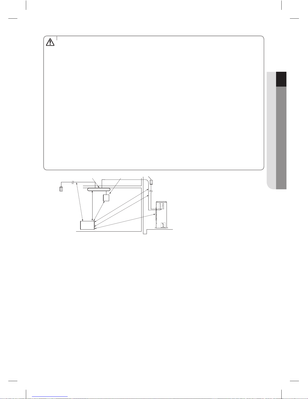
• Install the indoor unit away from any interfering sources such as radio, computer, stereo equipment and also
select a place where the electrical wiring work and an indoor unit installation are possible.
- Especially keep the unit at least 3m (9.84ft) away from the electrical equipment in an area where weak
electromagnetic waves are generated and install the protection tube to protect the main power cable and
communication cable.
- Make sure that there is no equipment that genetrates electromagnetic waves. If so, malfunction of the control
system may occur due to the effect of the electromagnetic wave. (For example: The remote control sensor of
the indoor unit may not have good reception in an area with fluorescent lamp style lighting.)
• Make sure the outdoor unit is installed in a safe place where it will not be obstructed by snowfall. The frame
should be installed in a place where the air inlet and heat exchanger of the unit are not buried in the snow.
• A ventilation system may be required when the outdoor unit is installed in a closed space or room, even though
R410a is not poisonous or flammable.
• Install railing around the outdoor unit to prevent it falling when the unit is installed on a high place such as the
roof of the building.
• Avoid installing the units in places near an exhaust pipe and ventilating opening exposed to corrosive gas,
oxides of sulfur, ammonia gas or sulfur gas herbicides. (These places need additional anticorrosive treatments.
Please contact manufacture to avoid corroding copper pipes or soldered parts.)
• There shouldn’t be any inflammable material such as wood and oil around the indoor unit. Otherwise, external
fire may spread to the product.
• According to the condition of power supply, electric noise or unstable voltage can occur malfunction of electric
parts or control system. (At the ship or places using power supply from electric generator… etc)
CAUTION
Outdoor
Unit
Indoor Unit
Remote Control
1m (3.28ft)
or more
1m (3.28ft)
or more
1.5m (4.92 ft)
or more
1.5m (4.92ft) or more
3m (9.84ft) or more
Breaker
Stereo
Breaker
1.5m (4.92ft) or more
Make sure that the water dripping from the drain hose runs away correctly and safely.
You should repaint or protect the damaged part so that the paint of the cabinet does not peel off and become rusty
during installation. When the cabinet becomes rusty, the life of an outdoor will be reduced.
AM0@@FXMDCH_IM_EN_03408A(1).indd 7 2013-03-04 오후 4:28:14
8
Installation location
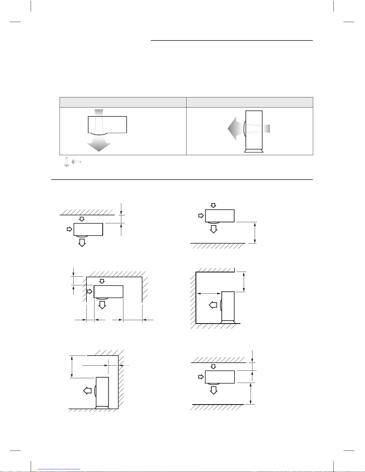
Make a space for ventilation and service as seen in the picture.
When multiple outdoor units are combined for installation, allow enough space for ventilation against a wall.
If the ventilation space is not allowed, product malfunction may occur.
The side with logo is the front side of the outdoor unit.
Figure Description
Top view Side view
Back side : Air intake
Front side : Air outlet
Front side :
Air outlet
Back side :
Air intake
• , Air flow direction.
When installing 1 outdoor unit
Unit: mm (inch)
When the air outlet is opposite the wall When the air outlet is toward the wall
300 (12) or more
1500 (60) or
more
When 3 sides of the outdoor unit are blocked by the wall The upper part of the outdoor unit is blocked and the air
outlet is toward the wall
300 (12) or
more
150 (6) or more
600 (24) or more
1500 (60) or
more
2000 (80) or
more
The upper part of the outdoor unit is blocked and the air
outlet is opposite the wall
When the walls are blocking front and the rear of the
outdoor unit
500 (20) or
more
300 (12) or more
1500 (60) or
more
300 (12) or
more
AM0@@FXMDCH_IM_EN_03408A(1).indd 8 2013-03-04 오후 4:28:14
9
ENGLISH
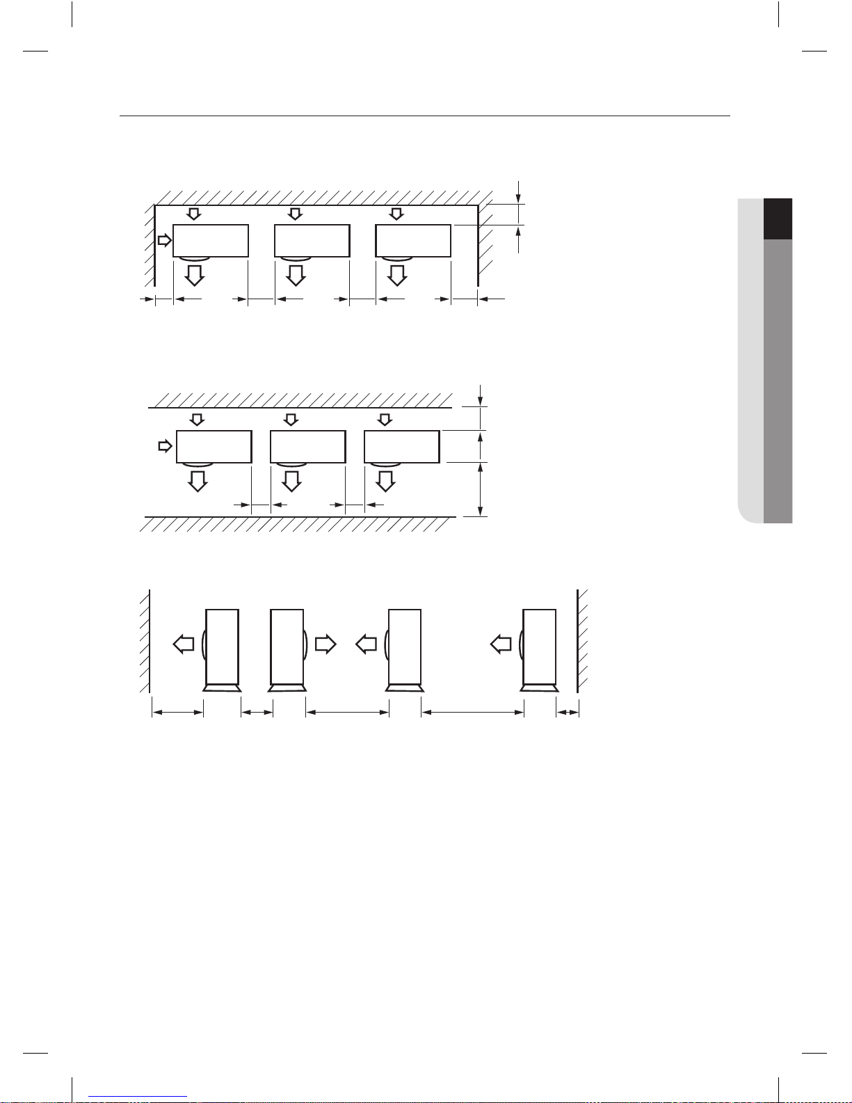
When installing more than 1 outdoor unit
Unit: mm (inch)
When 3 sides of the outdoor unit are blocked by the wall
300 (12) or
more
300 (12) or
more
600 (24) or
more
600 (24) or
more
600 (24) or
more
When the walls are blocking front and the rear of the outdoor units
300 (12) or
more
1500 (60) or
more
600 (24) or more 600 (24) or more
When front and rear side of the outdoor unit is toward the wall
1500 (60) or
more
600 (24) or
more
3000 (120) or
more
300 (12) or
more
3000 (120) or
more
AM0@@FXMDCH_IM_EN_03408A(1).indd 9 2013-03-04 오후 4:28:14
10
Installation location
Moving the Outdoor Unit
Select the moving route in advance.
Be sure that moving route is safe from the weight of the outdoor unit.
Do not slant the product more than 30˚ when carrying it. (Do not lay the product down sideways.)
The surface of the heat exchanger is sharp. Be careful not to get injured while moving and installing.
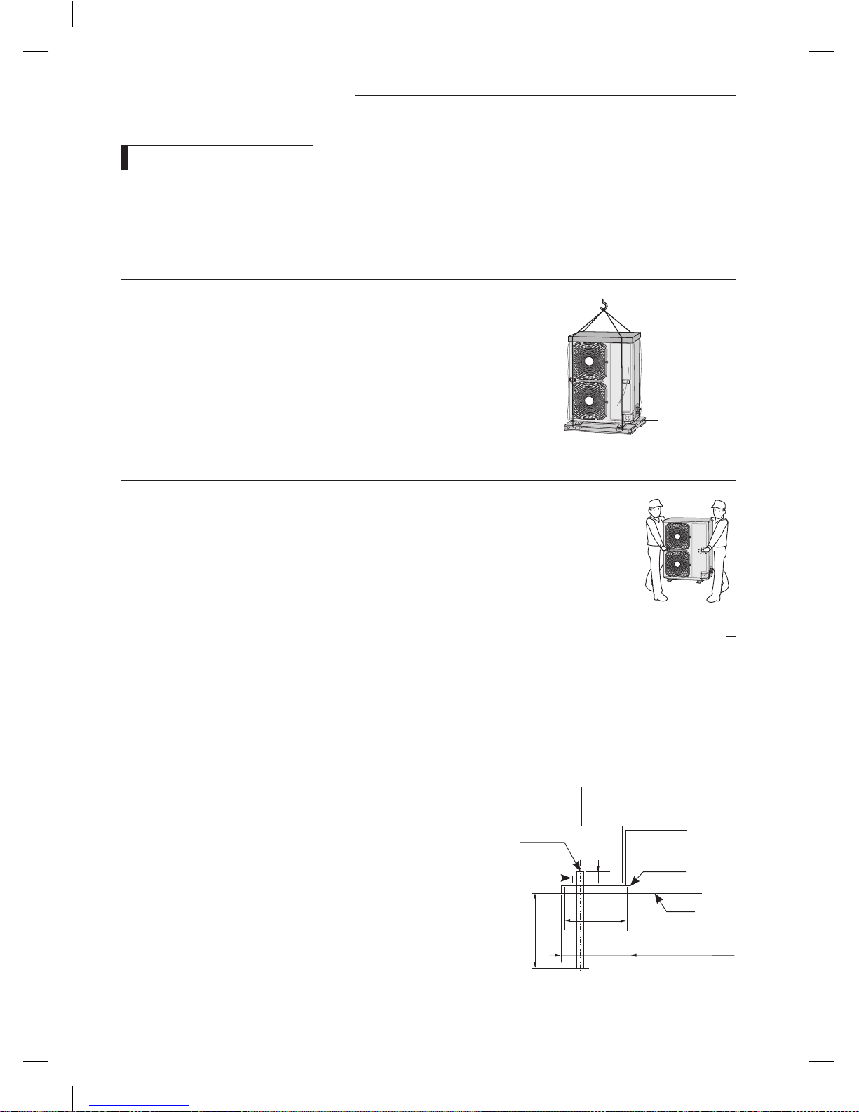
When moving with a crane or wire rope
When moving an outdoor unit to a higher place such as the rooftop.
- Fasten the wire rope as seen in the picture.
- Move the outdoor unit with the product packed to prevent possible product
damage during the transportation.
Wire rope/straps
Wood palette
When moving an outdoor unit with hands
Moving the outdoor unit by lifting up and carrying due to the short travel distance.
- Two people should carry the outdoor unit by holding transportation handle.
- Be careful not to damage the heat exchanger of the rear side of the outdoor unit during
transportation.
- Be careful not to get hurt by the sharp surface of the heat exchanger.
Installation and base ground work for an outdoor unit
Install the outdoor unit 150mm (6inch) higher than the base ground and install the drain hole to connect the pipe to the
drainage.
When the front fan of an outdoor unit is installed in a place where the average snowfall is more than 150mm (6inch), the
discharge duct should be attached to the outdoor unit.
The concrete foundation should be 1.5 times larger than bottom of the outdoor unit.
It is necessary to install wire mesh or steel bar when outdoor units are installed on a soft foundation.
When installing multiple outdoor units at the same place, install the
H beam on the base ground.
(When installing a number of outdoor units, you can install it on the
base ground.)
Install the H beam [150mm (6inch) x 150mm (6inch) x t10 : basic
specification] or vibration absorption frame to jut out from the base
ground.
After installing the H beam, apply corrosion protection.
Install a square pad [t=20mm (1inch) or more] to prevent vibration
from the outdoor unit onto the base ground. Place the outdoor unit
on the H beam and fix it with the bolt, nut and washer. (Fix with M10
basic anchor bolt, nut and washer.)
Outdoor unit
Anchor bolt
Nut, Spring
washer
H beam
Square pad
A+10~20mm
(0.5~1inch) or more
A
20mm
(1inch)
75mm
(3inch)
or more
AM0@@FXMDCH_IM_EN_03408A(1).indd 10 2013-03-04 오후 4:28:15
11
ENGLISH
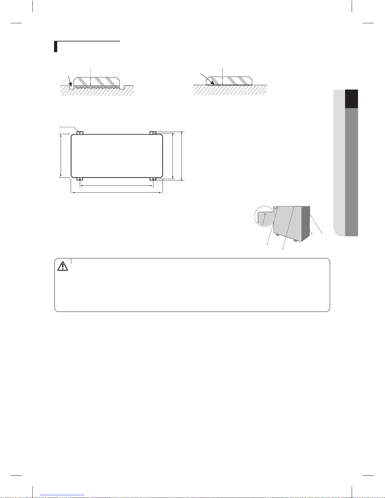
Base ground work
< When installing on the ground >
Drain hole
150mm (6inch) or more
< When installing on the roof >
Install the outdoor unit
horizontally on the ground
150mm (6inch) or more
The outdoor unit should be supported within the range of measurement below for base ground work.
Unit: mm (inch)
Anchor bolt position
330 (12.99)
620 (24.40)
940 (37.00)
360 (14.17)
384 (15.11)
When the outdoor unit needs to be supported, fix it with wire as shown in the
picture.
- Slightly unwind the four screws on the cover top of the outdoor unit.
- Wind wires round the four screws and fasten the screws again.
- Fix the wires to the ground.
• If the outdoor unit is not fixed securely, product may fall and it might cause loss of life or property damage.
• Do not install the outdoor unit on a wood palette.
• Fix the outdoor unit securely to the base ground with anchor bolts.
• The manufacturer is not responsible for the damage occurred by not adhering to the standard of the installation.
• To protect the outdoor unit from external condition such as rain, install it on the base ground and connect the
drain pipe to the drainage.
CAUTION
AM0@@FXMDCH_IM_EN_03408A(1).indd 11 2013-03-04 오후 4:28:15
12
Refrigerant pipe installation
Refrigerant pipe work
The length of refrigerant pipe should be as short as possible and the height difference between an indoor unit and
outdoor unit should be minimized.
The piping length between the outdoor unit and the indoor unit may not exceed the allowable piping length, height
difference, and the allowable length after branching is done.
The pressure of the R410A is high. Use only certified refrigerant pipe and follow the installation method.
After pipe installation, charge the refrigerant according to the length of the pipe and R410A refrigerant should be used.
Use clean refrigerant pipe and there shouldn’t be any harmful ion, oxide, dust, iron content or moisture inside pipe.
Use tools and accessories that fit on R410A only.
• When installing, make sure there is no leakage. When collecting the refrigerant, stop the compressor first before
removing the connection pipe. If the refrigerant pipe is not properly connected and the compressor works
with the service valve open, the pipe inhales the air and it makes the pressure inside of the refrigerant cycle
abnormally high. It may cause explosion and injury.
WARNING
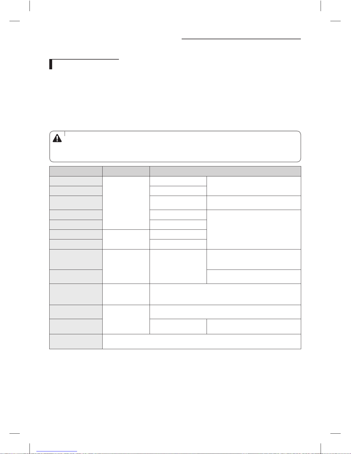
Tool Work If compatible with conventional tool
Pipe cutter
Refrigerant pipe work
Pipe cutting
Compatible
Flaring tool Pipe flaring
Refrigerant oil
Apply refrigerant oil on
flared part
Exclusive ether oil, ester oil, alkali benzene oil or
synthetic oil
Torque wrench Connect flare nut with pipe
Compatible
Pст.)ipe bender Pipe bending
Nitrogen gas
Air tightening test
Inhibition of oxidization
Brazing tool Pipe brazing
Manifold gauge
Air tightening test ~
additional refrigerant
charging
Vacuuming, charging and
checking operation
Need exclusive one to prevent mixture of R22
refrigerant oil use and also the measurement is
not available due to the high pressure.
Refrigerant charging
hose
Need exclusive one due to the refrigerant
leakage or inflow of impurities.
Vacuum pump Vacuum drying
Compatible (Use products which contain the check valve to prevent the oil
from flowing backward into the outdoor unit.)
Use the one that can be vacuumed up to 100.7kpa(5Torr.-755mmHg).
Scale for refrigerant
charging
Compatible
Gas leak detector Gas leak test
Need exclusive one
( The one for R134A can be used)
Flare nut
You must use the flare nut equipped with product.
Refrigerant leakage may occur when the conventional flare nut for R22 is used.
AM0@@FXMDCH_IM_EN_03408A(1).indd 12 2013-03-04 오후 4:28:16
13
ENGLISH
Selecting refrigerant pipe
Temper grade and minimum thickness of the refrigerant pipe
Outer diameter [mm (inch)] Minimum thickness [mm (inch)] Temper grade
Ø6.35 (1/4) 0.7 (0.028)
Annealed
Ø9.52 (3/8) 0.7 (0.028)
Ø12.70 (1/2) 0.8 (0.031)
Ø15.88 (5/8) 1.0 (0.039)
Ø19.05 (3/4) 0.9 (0.035)
Drawn
Ø22.23 (7/8) 0.9 (0.035)
Make sure to use C1220T-1/2H (Semi-hard) or C1220T-H pipe for more than Ø19.05mm (3/4inch).
In case of using C1220T-O (Soft) pipe for Ø19.05mm (3/4inch), pipe may be broken, which can result in an injury.
Pipe installation between an outdoor unit and the first Y-joint
Outdoor unit capacity
[HP(Ton)]
Liquid pipe [mm (inch)] Gas pipe [mm (inch)]
One step upgraded pipe
[mm (inch)]
4(3) Ø9.52 (3/8) Ø15.88 (5/8) Ø19.05 (3/4)
5(4) Ø9.52 (3/8) Ø15.88 (5/8) Ø19.05 (3/4)
6(5) Ø9.52 (3/8) Ø19.05 (3/4) Ø22.23 (7/8)
Install the refrigerant pipe according to main pipe size of each outdoor unit capacity.
When the pipe length between an outdoor unit and the farthest indoor unit including elbow exceeds 90m (295ft), the
gas pipe size should be upgraded one step among the main pipes from the outdoor unit to the first Y-joint. (The liquid
pipe size will be maintained.)
If the capacity of the outdoor unit can decline due to the pipe length, upgrade the pipe size one step (gas pipe).
Main pipe size up
First Y-joint
Pipe installation between Y-joints
Indoor unit total capacity
[kW (Btu/h)]
Pipe diameter (O•D•mm)
Liquid pipe [mm (inch)] Gas pipe [mm (inch)]
X ≤ 15.0 (51000)
Ø9.52 (3/8)
Ø15.88 (5/8)
15.0 (51000) < X ≤ 23.2 (79000) Ø19.05 (3/4)
AM0@@FXMDCH_IM_EN_03408A(1).indd 13 2013-03-04 오후 4:28:16

14
Refrigerant pipe installation
Selecting Y-joint
Select the first Y-joint according to main pipe size of each outdoor unit capacity.
Select the other Y-joints according to the total indoor unit capacity under the selected Y-joint.
Selecting the first Y-joint Other Y-joints
Outdoor unit capacity
[HP(Ton)]
Y-joint model
Total indoor unit capacity under the
selected Y-joint [kW (Btu/h)]
Y-joint model
4(3) MXJ-YA1509 X ≤ 15.0 (51000) MXJ-YA1509
5(4) MXJ-YA1509 15.0 (51000) < X ≤ 40.6 (138000) MXJ-YA2512
6(5) MXJ-YA2512
Keeping refrigerant pipe
To prevent foreign materials or water from entering the pipe, it is important to keep the refrigerant pipe clean and dry and to
seal it during installation.
Apply correct sealing method depending on the environment.
Exposure place Exposure time Sealing type
Outside exposure
Longer than one month Pipe pinch
Shorter than one month Taping
Inside exposure - Taping
Refrigerant pipe brazing and safety information
Important information for refrigerant pipe work
Make sure that there is no moisture inside the pipe.
Make sure that there are no foreign materials and impurities in the pipe.
Make sure that there is no leak.
Make sure to follow the instruction when brazing and keeping the pipe.
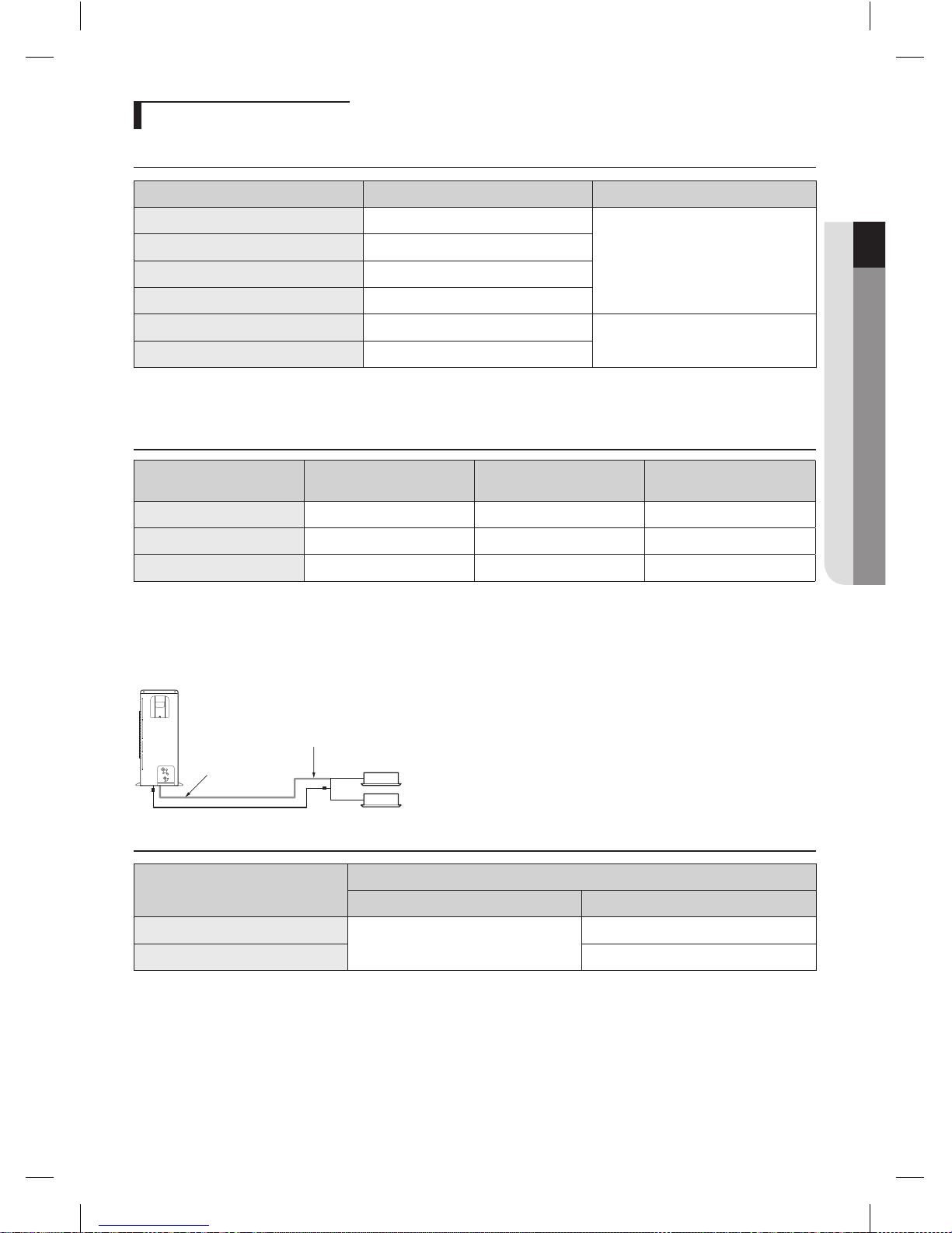
Nitrogen flushing brazing
Use Nitrogen gas when brazing the pipes as shown in the picture.
If you do not perform nitrogen flushing when brazing the pipes, oxide may form inside the pipe. It can cause the damage
of the important parts such as compressor, valves.
Adjust the flow rate of the Nitrogen flushing with a pressure regulator to maintain 0.05m3/h or less.
Brazing part
Nitrogen gas
Ø6.35(1/4") copper pipe
Shut-off
valve
Taping
Flow meter
High pressure hose
Pressure regulator
AM0@@FXMDCH_IM_EN_03408A(1).indd 14 2013-03-04 오후 4:28:16
 Loading...