

Samsung AM022NN1PEH/TK, AM017NN1PEH/TK, AM022NN1DEH/TK, AM028NN1DEH/TK, AM036NN1DEH/TK Installation Manual
...
Air conditioner
Installation manual
AM∗∗∗NN1PEH / AM∗∗∗NN1DEH
• Thank you for purchasing this Samsung air conditioner.
• Before operating this unit, please read this manual carefully and retain it for future
reference.
DB68-07553A-00
DVM TK Wind-Free 1way IM EN_DB68-07553A-00.indb 1 2017-12-01 오후 2:18:59
2
English
Contents
Safety Information 3
Installation Procedure 5
Step 1 Checking and preparing accessories
Step 2 Choosing the installation location
Step 3 Optional: Insulating the body of the indoor unit
Step 4 Installing the indoor unit
Step 5 Purging inert gas from the indoor unit
Step 6 Cutting and flaring the pipes
Step 7 Connecting the assembly pipes to the refrigerant pipes
Step 8 Performing the gas leak test
Step 9 Insulating the refrigerant pipes
Step 10 Installing the drain hose and drain pipe
Step 11 Performing the drainage test
Step 12 Connecting the power and communication cables
Step 13 Optional: Extending the power cable
Step 14 Setting the indoor unit addresses and the installation options
Appendix 38
Troubleshooting
Instruction for packing and unpacking the unit
Technical Specifications
DVM TK Wind-Free 1way IM EN_DB68-07553A-00.indb 2 2017-12-01 오후 2:18:59
3
English
Safety Information
WARNING
• Hazards or unsafe practices that may result in severe
personal injury or death.
CAUTION
• Hazards or unsafe practices that may result in minor
personal injury or property damage.
• Carefully follow the precautions listed below because they
are essential to guarantee the safety of the equipment.
WARNING
• Always disconnect the air conditioner from the power
supply before servicing it or accessing its internal
components.
• Verify that installation and testing operations are
performed by qualified personnel.
• Verify that the air conditioner is not installed in an
easily accessible area.
General information
WARNING
• Carefully read the content of this manual before
installing the air conditioner and store the manual in
a safe place in order to be able to use it as reference
after installation.
• For maximum safety, installers should always carefully
read the following warnings.
• Store the operation and installation manual in a safe
location and remember to hand it over to the new
owner if the air conditioner is sold or transferred.
• This manual explains how to install an indoor unit with
a split system with two SAMSUNG units. The use of
other types of units with different control systems may
damage the units and invalidate the warranty. The
manufacturer shall not be responsible for damages
arising from the use of non compliant units.
• The manufacturer shall not be responsible for damage
originating from unauthorized changes or the
improper connection of electric and requirements set
forth in the “Operating limits” table, included in the
manual, shall immediately invalidate the warranty.
• The air conditioner should be used only for the applications for
which it has been designed: the indoor unit is not suitable to
be installed in areas used for laundry.
• Do not use the units if damaged. If problems occur, switch
the unit off and disconnect it from the power supply.
• In order to prevent electric shocks, fires or injuries,
always stop the unit, disable the protection switch
and contact SAMSUNG’s technical support if the unit
produces smoke, if the power cable is hot or damaged
or if the unit is very noisy.
• Always remember to inspect the unit, electric
connections, refrigerant tubes and protections
regularly. These operations should be performed by
qualified personnel only.
• The unit contains moving parts, which should always
be kept out of the reach of children.
• Do not attempt to repair, move, alter or reinstall the
unit. If performed by unauthorized personnel, these
operations may cause electric shocks or fires.
• Do not place containers with liquids or other objects
on the unit.
• All the materials used for the manufacture and
packaging of the air conditioner are recyclable.
• The packing material and exhaust batteries of the
remote controller(optional) must be disposed of in
accordance with current laws.
• The air conditioner contains a refrigerant that has
to be disposed of as special waste. At the end of its
life cycle, the air conditioner must be disposed of in
authorized centres or returned to the retailer so that it
can be disposed of correctly and safely.
Installing the unit
WARNING
IMPORTANT: When installing the unit, always remember
to connect first the refrigerant tubes, then the electrical
lines.
• Always disassemble the electric lines before the
refrigerant tubes.
• Upon receipt, inspect the product to verify that
it has not been damaged during transport. If the
product appears damaged, DO NOT INSTALL it and
immediately report the damage to the carrier or
retailer (if the installer or the authorized technician has
collected the material from the retailer.)
• After completing the installation, always carry out a
functional test and provide the instructions on how to
operate the air conditioner to the user.
Safety Information
Safety Information
DVM TK Wind-Free 1way IM EN_DB68-07553A-00.indb 3 2017-12-01 오후 2:18:59
4
Safety Information
English
Safety Information
• Do not use the air conditioner in environments with
hazardous substances or close to equipment that
release free flames to avoid the occurrence of fires,
explosions or injuries.
• Our units must be installed in compliance with the
space specifications presented in the installation
manual in order to ensure accessibility from both sides
and allow repairs or maintenance operations to be
carried out.
The unit’s components must be accessible and easy to
disassemble without endangering people and objects.
For this reason, where it is not observed as indicated
into the Installation Manual, the cost necessary
to reach and repair the unit (in safety, as required
by current regulations in force) with slings, trucks,
scaffolding or any other means of elevation won’t be
considered in-warranty and charged to end user.
Power supply line, fuse or circuit
breaker
WARNING
• Always make sure that the power supply is compliant
with current safety standards. Always install the air
conditioner in compliance with current local safety
standards.
• Always verify that a suitable grounding connection is
available.
• Verify that the voltage and frequency of the power
supply comply with the specifications and that the
installed power is sufficient to ensure the operation of
any other domestic appliance connected to the same
electric lines.
• Always verify that the cut-off and protection switches
are suitably dimensioned.
• Verify that the air conditioner is connected to the
power supply in accordance with the instructions
provided in the wiring diagram included in the manual.
• Always verify that electric connections (cable entry,
section of leads, protections…) are compliant with
the electric specifications and with the instructions
provided in the wiring scheme. Always verify that all
connections comply with the standards applicable to
the installation of air conditioners.
• Devices disconnected from the power supply should
be completely disconnected in the condition of
overvoltage category.
• Be sure not to perform power cable modification,
extension wiring, and multiple wire connection.
– It may cause electric shock or fire due to poor
connection, poor insulation, or current limit override.
– When extension wiring is required due to power
line damage, refer to Step 13 Optional: Extending
the power cable in the installation manual.
CAUTION
Make sure that you earth the cables.
• Do not connect the earth wire to the gas pipe, water
pipe, lighting rod or telephone wire. If earthing is not
complete, electric shock or fire may occur.
Install the circuit breaker.
• If the circuit breaker is not installed, electric shock or
fire may occur.
Make sure that the condensed water dripping from the
drain hose runs out properly and safely.
Install the power cable and communication cable of
the indoor and outdoor unit at least 1m away from the
electric appliance.
Install the indoor unit away from lighting apparatus
using the ballast.
• If you use the wireless remote control, reception error
may occur due to the ballast of the lighting apparatus.
DVM TK Wind-Free 1way IM EN_DB68-07553A-00.indb 4 2017-12-01 오후 2:18:59
5
English
Installation Procedure
Installation Procedure
Installation Procedure
Step 1 Checking and preparing
accessories
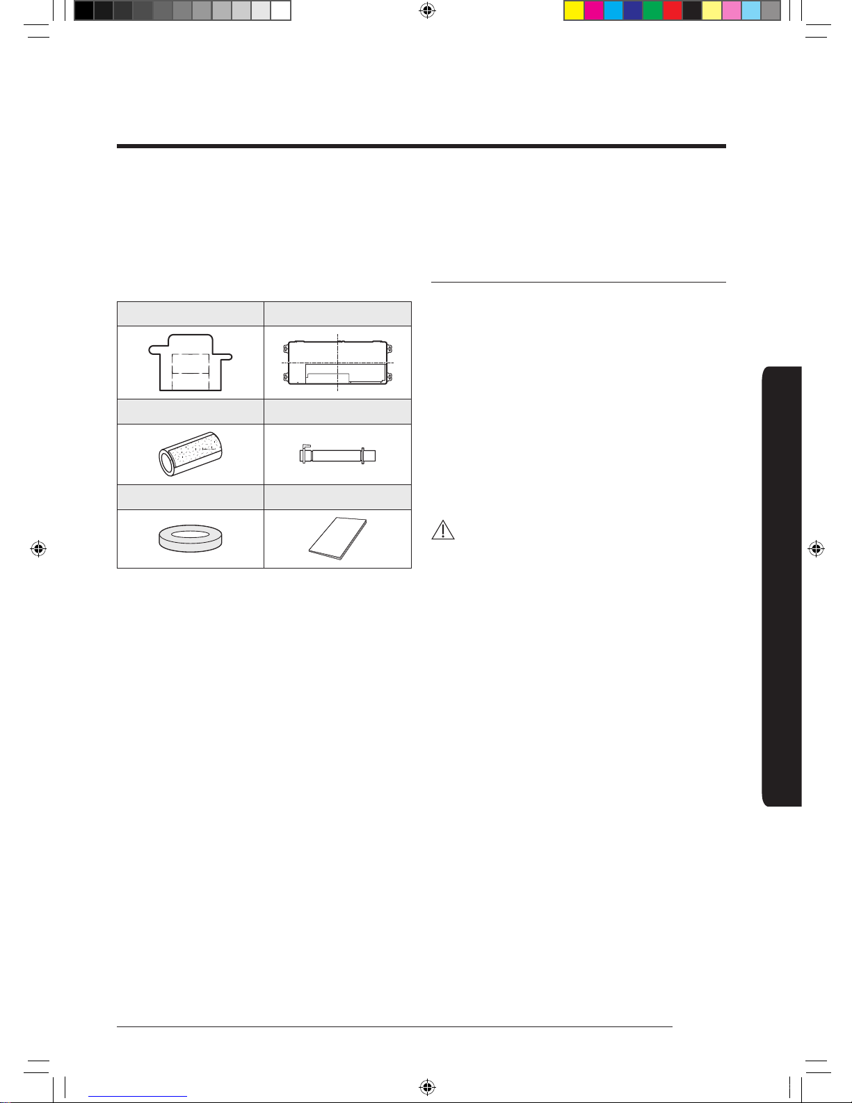
The following accessories are supplied with the indoor
unit. The type and quantity may differ, depending on the
specifications.
Installation template Dimension gauge
Insulation drain Flexible hose
Rubber Installation manual
Step 2 Choosing the installation
location
Installation location requirements
• There must be no obstacles near the air inlet and
outlet.
• Install the indoor unit on a ceiling that can support its
weight.
• Maintain sufficient clearance around the indoor unit.
• Before installing the indoor unit, be sure to check
whether the chosen location is well-drained.
• The indoor unit must be installed such that it is beyond
public access and is not touchable by users.
• Rigid wall without vibration.
• Where it is not exposed to direct sunshine.
• Where the air filter can be removed and cleaned easily.
CAUTION
• As a rule, the unit cannot be installed at a height of
less that 2.5m.
• If you install the cassette or duct type indoor unit on
the ceiling with humidity over 80%, you must apply
extra 10mm of polyethylene foam or other insulation
with similar material on the body of the indoor unit.
Do not install the air conditioner in following places.
• Place where there is mineral oil or arsenic acid. Resin
parts flame and the accessories may drop or water
may leak. The capacity of the heat exchanger may
reduce or the air conditioner may be out of order.
• The place where corrosive gas such as sulphuric acid
gas generates from the vent pipe or air outlet.
• The copper pipe or connection pipe may corrode and
refrigerant may leak.
• The place where there is a machine that generates
electromagnetic waves. The air conditioner may not
operate normally due to control system.
• The place where there is a danger of existing
combustible gas, carbon fibre or flammable dust.
• The place where thinner or gasoline is handled. Gas
may leak and it may cause fire.
DVM TK Wind-Free 1way IM EN_DB68-07553A-00.indb 5 2017-12-01 오후 2:19:00
6
Installation Procedure
English
Installation Procedure
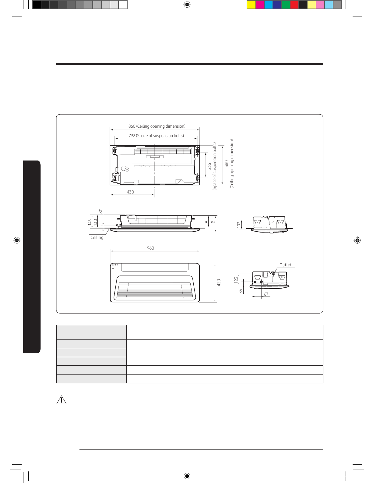
Indoor unit dimensions
Slim 1way cassette (Small)
(Unit: mm)
67
145
107
430
A
B
123
36
130
80
420
960
792 (Space of suspension bolts)
860 (Ceiling opening dimension)
Ceiling
Outlet
235
(Space of suspension bolts)
380
(Ceiling opening dimension)
Model
AM017NN1PEH∗
AM022NN1PEH∗
A 134
B 180
Liquid pipe connection Ø6.35
Gas pipe connection Ø12.7
Drain hose connection VP20 (outer diameter: Ø26, innder diameter: Ø20)
CAUTION
• If the indoor unit is not leveled, drainage water height measurement may be wrong and it cause water may leak into
the room.
DVM TK Wind-Free 1way IM EN_DB68-07553A-00.indb 6 2017-12-01 오후 2:19:00
7
English
Installation Procedure
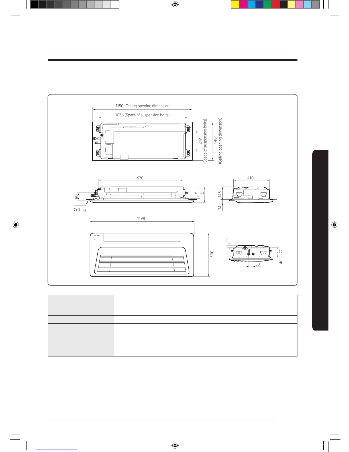
Slim 1way cassette (Medium)
(Unit: mm)
410
14534
22
46
50
77
970
80
A
B
500
1198
Ceiling
1150 (Ceiling opening dimension)
249
(Space of suspension bolts)
440
(Ceiling opening dimension)
1036 (Space of suspension bolts)
Model
AM022NN1DEH∗
AM028NN1DEH∗
AM036NN1DEH∗
A 130
B 179
Liquid pipe connection Ø6.35
Gas pipe connection Ø12.7
Drain hose connection VP20 (outer diameter: Ø26, innder diameter: Ø20)
DVM TK Wind-Free 1way IM EN_DB68-07553A-00.indb 7 2017-12-01 오후 2:19:00
8
Installation Procedure
English
Installation Procedure
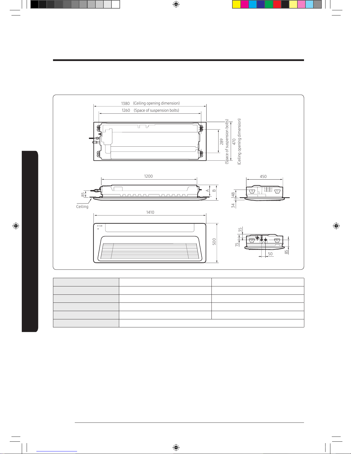
Slim 1way cassette (Large)
(Unit: mm)
(Ceiling opening dimension)
(Ceiling opening dimension)
1380
1410
500
289
470
(Space of suspension bolts)
1260
85
35
15
1200
85
A
B
Ceiling
450
14834
50
(Space of suspension bolts)
Model AM056NN1DEH∗ AM071NN1DEH∗
A 133 138
B 180 180
Liquid pipe connection Ø6.35 Ø9.52
Gas pipe connection Ø12.7 Ø15.88
Drain hose connection VP20 (outer diameter: Ø26, innder diameter: Ø20)
DVM TK Wind-Free 1way IM EN_DB68-07553A-00.indb 8 2017-12-01 오후 2:19:00
9
English
Installation Procedure
Spacing requirements
A: 1500 mm or more
A
A
A
A
CAUTION
• The indoor unit must be installed according to the
specified distances in order to permit accessibility
from each side, to guarantee correct operation,
maintenance, and repair of the unit.
The components of the indoor unit must be reachable
and removable under safe conditions for people and
the unit.
• Do not hold the discharge while carrying the indoor
unit to avoid the possibility of breakage.
• You must hold the hanger plate on the corner and
carry the indoor unit.
Step 3 Optional: Insulating the body of
the indoor unit
If you install a cassette type indoor unit on the ceiling
when temperature is over 27°C and humidity is over
80%, you must apply an extra 10 mm thick polyethylene
insulation or a similar type of insulation to the body of the
indoor unit.
Cut away the part where pipes are pulled out for the
insulating work.
Insulate the end of the pipe and some curved area by
using separate insulator.
Step 4 Installing the indoor unit
When deciding on the location of the air conditioner the
following restrictions must be taken into account.
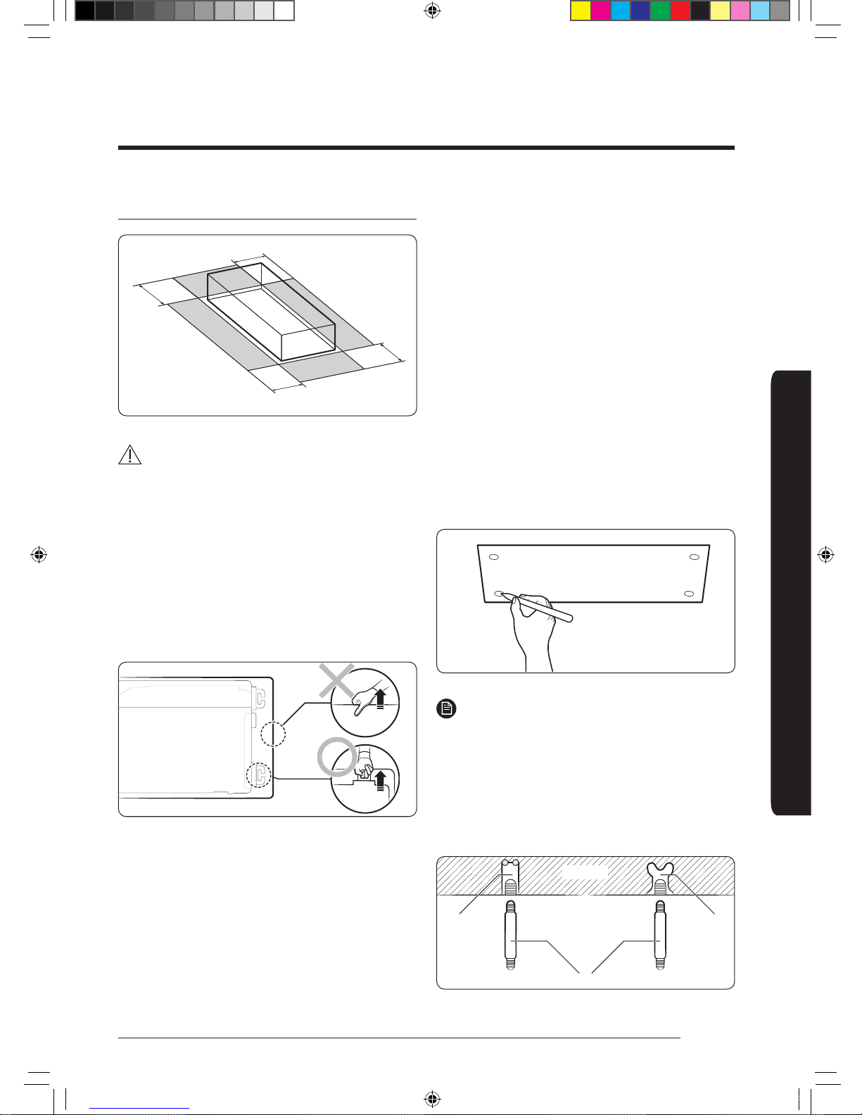
1 Place the pattern sheet on the ceiling at the spot
where you want to install the indoor unit.
NOTE
• Since the diagram is made of paper, it may shrink
or stretch slightly due to temperature or humidity.
For this reason, before drilling the holes, be sure
to maintain the correct dimensions between the
markings.
2 Insert bolt anchors, use existing ceiling supports or
construct a suitable support as shown in figure.
Concrete
Hole in anchor
Hole in plug
Suspension bolt (ø9.52 or M10)
Insert
DVM TK Wind-Free 1way IM EN_DB68-07553A-00.indb 9 2017-12-01 오후 2:19:01
10
Installation Procedure
English
Installation Procedure
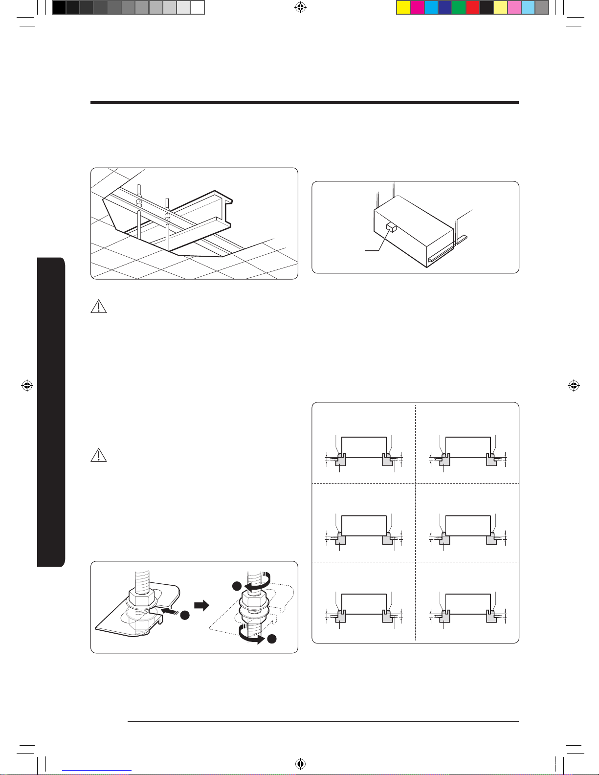
3 Install the suspension bolts, depending on the ceiling
type.
Ceiling support
CAUTION
• Make sure that the ceiling is strong enough to support
the weight of the indoor unit. Before hanging the unit,
test the strength of each attached suspension bolt.
• If the length of the suspension bolt is more than 1.5 m,
you are required to prevent vibration.
• If this is not possible, create an opening on the false
ceiling in order to be able to use it to perform the
required operations on the indoor unit.
4 Screw eight nuts and washers to the suspension bolts,
making space for hanging the indoor unit.
CAUTION
• You must install all of the suspension rods.
• It is important to leave sufficient space in the false
ceiling to allow access for maintenance or repairs to
the drainage pipe connection, the refrigerant pipe
connection, or to remove the unit if necessary.
5 Hang the indoor unit to the suspension bolts between
two nuts. Screw the nuts to suspend the unit.
1
2
2
6 Check the level of the indoor unit by using a leveler.
• A tilt of the indoor unit may cause malfunction of a
built-in float switch and water leaks.
Level
7 Adjust the unit to the appropriate position, taking into
account the installation area for the front panel.
• Place the pattern sheet on the indoor unit.
• Adjust the space between the ceiling and the
indoor unit by using a dimension gauge.
• Fix the indoor unit securely after adjusting the level
of the unit by using a leveller.
• Remove the pattern sheet and install the front
panel.
Slim 1way cassette
(Small, Wind-Free)
Indoor unit
Slim 1way cassette
(Medium, Wind-Free)
Slim 1way cassette
(Large, Wind-Free)
Air outlet side
Jig
6.0
8.0
Ceiling
Air inlet side
Indoor unit
Air outlet side
Jig
10
10
Ceiling
Air inlet side
Indoor unit
Air outlet side
Jig
10
10
Ceiling
Air inlet side
Slim 1way cassette
(Small)
Indoor unit
Slim 1way cassette
(Medium)
Slim 1way cassette
(Large)
Air outlet side
Jig
16
18
Ceiling
Air inlet side
Indoor unit
Air outlet side
Jig
15
15
Ceiling
Air inlet side
Indoor unit
Air outlet side
Jig
15
15
Ceiling
Air inlet side
DVM TK Wind-Free 1way IM EN_DB68-07553A-00.indb 10 2017-12-01 오후 2:19:01
11
English
Installation Procedure
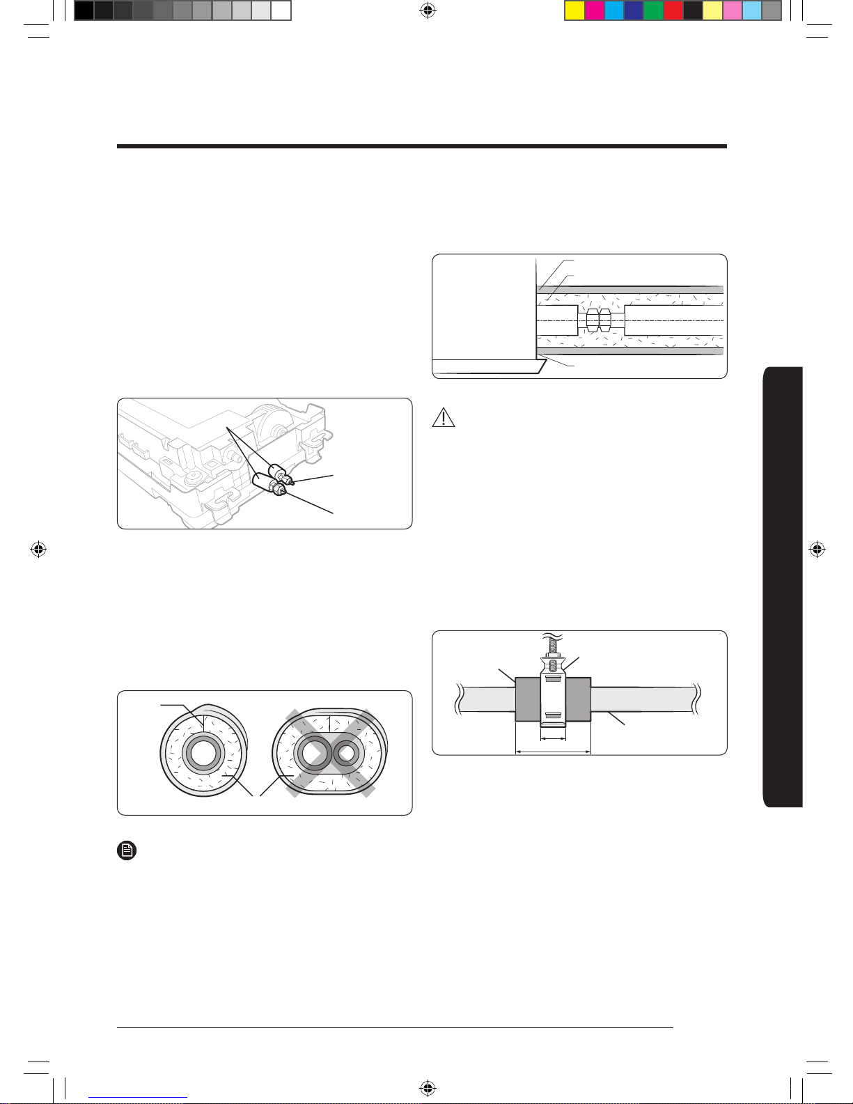
Step 5 Purging inert gas from the
indoor unit
The indoor unit comes with nitrogen gas (inert gas)
charged at the factory. Therefore, all inert gas must be
purged before connecting the assembly piping.
Unscrew the pinch pipe at the end of each refrigerant
pipe.
Liquid side
Gas side
Insulator
NOTE
• To prevent dirt or foreign objects from getting into the
pipes during installation, do not remove the pinch pipe
completely until you are ready to connect the piping.
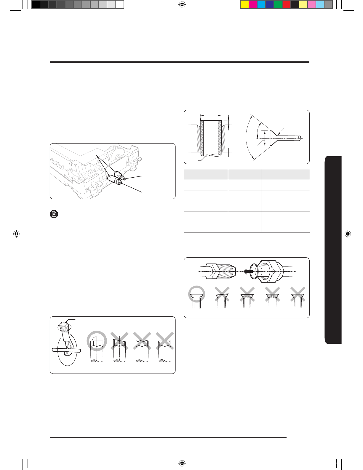
Step 6 Cutting and flaring the pipes
1 Make sure that you have the required tools available:
pipe cutter, reamer, flaring tool, and pipe holder.
2 If you wish to shorten the pipes, cut them with a pipe
cutter, ensuring that the cut edge remains at a 90°
angle to the side of the pipe. Refer to the illustrations
below for examples of edges cut correctly and
incorrectly.
Pipe cutter
Pipe
Oblique
Rough
Burr
3 To prevent any gas from leaking out, remove all burrs
at the cut edge of the pipe, using a reamer.
4 Slide a flare nut on to the pipe and modify the flare.
Pipe
Flare
D
A
Flare
R 0.4 to 0.8 mm
D
L
90° ±2°
45° ±2°
Outer Diameter (D) Depth (A) Flare dimension (L)
Ø6.35 mm 1.3 mm 8.7 to 9.1 mm
Ø9.52 mm 1.8 mm 12.8 to 13.2 mm
Ø12.70 mm 2.0 mm 16.2 to 16.6 mm
Ø15.88 mm 2.2 mm 19.3 to 19.7 mm
Ø19.05 mm 2.2 mm 23.6 to 24.0 mm
5 Check that the flaring is correct, referring to the
illustrations below for examples of incorrect flaring.
Correct
Inclined
Damaged
Surface
Cracked
Uneven
Thickness
DVM TK Wind-Free 1way IM EN_DB68-07553A-00.indb 11 2017-12-01 오후 2:19:01
12
Installation Procedure
English
Installation Procedure
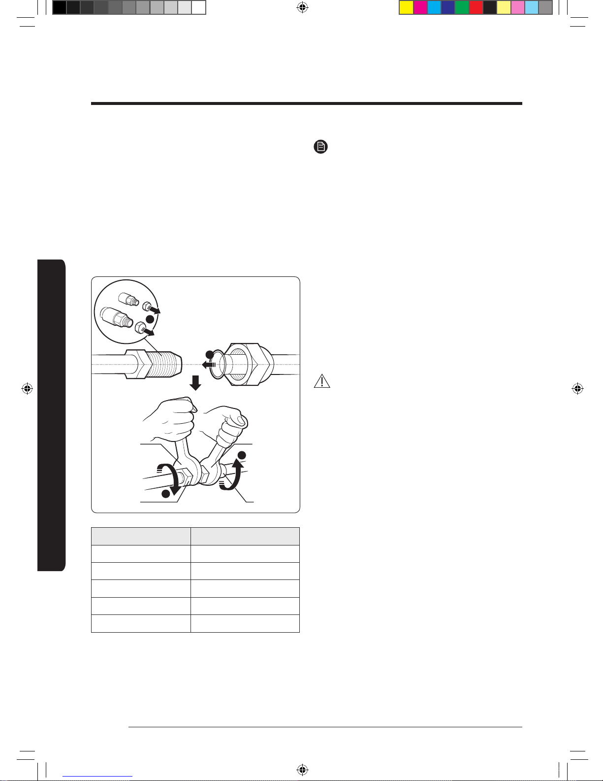
Step 7 Connecting the assembly pipes
to the refrigerant pipes
There are two refrigerant pipes of different diameters :
• A smaller one for the liquid refrigerant.
• A larger one for the gas refrigerant. The inside of
copper pipe must be clean and has no dust.
1 Remove the pinch pipe on the pipes and connect the
assembly pipes to each pipe, tightening the nuts, first
manually and then with a torque wrench, a spanner
applying the following torque.
Torque
wrench
Flare nut
Spanner
Union
1
2
3
3
Outer Diameter (mm) Torque (N•m)
Ø6.35 14 to 18
Ø9.52 34 to 42
Ø12.70 49 to 61
Ø15.88 68 to 82
Ø19.05 100 to 120
(1 N•m=10kgf•cm)
NOTE
• If the pipes must be shortened, see Step 6 Cutting
and flaring the pipes on page 11.
2 Be sure to use an insulator thick enough to cover the
refrigerant tube to protect the condensate water on
the outside of the pipe falling onto the floor and to
improve the efficiency of the unit.
3 Cut off any excess foam insulation.
4 Make sure that there are no cracks or waves on the
bent area.
5 It would be necessary to double the insulation
thickness (10 mm or more) to prevent condensation
even on the insulator when if the installed area is
warm and humid.
6 Do not use joints or extensions for the pipes
connecting the indoor and outdoor units. The only
permitted connections are those for which the units
are designed.
CAUTION
• Connect the indoor and outdoor units using pipes
with flared connections (not supplied). For the lines,
use insulated, unwelded, degreased and deoxidized
copper pipe (Cu DHP type to ISO 1337 or UNI EN 12735-
1), suitable for operating pressures of at least 4.2 MPa
and for a burst pressure of at least 20.7 MPa. Copper
pipe for hydro-sanitary applications is completely
unsuitable.
• For sizing and limits (height difference, line length,
max. bends, refrigerant charge, etc.) see the outdoor
unit installation manual.
• All refrigerant connection must be accessible, in order
to permit either unit maintenance or removing it
completely.
• If the pipes require brazing, make sure that oxygen
free nitrogen (OFN) is flowing through the system.
• Nitrogen blowing pressure range is 0.02 to 0.05 MPa.
DVM TK Wind-Free 1way IM EN_DB68-07553A-00.indb 12 2017-12-01 오후 2:19:02
13
English
Installation Procedure
Step 8 Performing the gas leak test
To identify potential gas leaks on the indoor unit, inspect
the connection area of each refrigerant pipe using a leak
detector for R-410A.
Before recreating the vacuum and recirculating the
refrigerant gas, pressurize the whole system with
nitrogen (using a cylinder with a pressure reducer) at a
pressure above 4.1 MPa in order to immediately detect
leaks on the refrigerant fittings.
Made vacuum for 15 minutes and pressurizing system
with nitrogen.
Liquid side
Gas side
Insulator
Step 9 Insulating the refrigerant pipes
Once you have checked that there are no leaks in the
system, you can insulate the piping and hose.
1 To avoid condensation problems, place Acrylonitrile
Butadien Rubber separately around each refrigerant
pipe.
No gap
NBR (T13.0 or thicker)
NOTE
• Always make the seam of pipes face upwards.
2 Wind insulating tape around the pipes and drain hose
avoiding compressing the insulation too much.
3 Finish wrapping insulating tape around the rest of the
pipes leading to the outdoor unit.
4 The pipes and electrical cables connecting the indoor
unit with the outdoor unit must be fixed to the wall
with suitable ducts.
Insulation cover pipe
Insulation pipe
Be sure to overlap the insulation.
Indoor unit
CAUTION
• Must fit tightly against body without any gap.
• Install the insulation not to get wider and use the
adhesives on the connection part of it to prevent
moisture from entering.
• Wind the refrigerant pipe with insulation tape if it is
exposed to outside sunlight.
• Install the refrigerant pipe respecting that the
insulation does not get thinner on the bent part or
hanger of pipe.
• Add the additional insulation if the insulation plate
gets thinner.
Refrigerant pipe insulation
Hanger
Additional
insulation
a
a x 3
• Must fit tightly against body without any gap.
• All refrigerant connection must be accessible, in order
to permit either unit maintenance or removal.
DVM TK Wind-Free 1way IM EN_DB68-07553A-00.indb 13 2017-12-01 오후 2:19:02
 Loading...