

Samsung AM009FN4DCH User Manual

Contents
Safety precautions ..............................................................................................2
Accessories .....................................................................................................5
Selecting the installation location ................................................................................5
Deciding on where to install the indoor unit ......................................................................7
Indoor unit installation ..........................................................................................8
Purging the unit ................................................................................................9
Connecting the refrigerant pipe.................................................................................10
Cutting/aring the pipes .......................................................................................11
Performing leak test & insulation................................................................................12
Drainpipe and drain hose installation............................................................................15
Bushing bracket installation ....................................................................................18
Wiring work ...................................................................................................19
Setting an indoor unit address and installation option............................................................23
Final checks and user tips.......................................................................................33
Troubleshooting ...............................................................................................34
Safety precautions
Carefully follow the precautions listed below because they are essential to guarantee the safety of the equipment.
t Always disconnect the air conditioner from the power supply before servicing it or
accessing its internal components.
WARNING
t Verify that installation and testing operations are performed by qualied personnel.
t Verify that the air conditioner is not installed in an easily accessible area.
General information
X Carefully read the content of this manual before installing the air conditioner and store the manual in a safe place
in order to be able to use it as reference after installation.
X For maximum safety, installers should always carefully read the following warnings.
X Store the operation and installation manual in a safe location and remember to hand it over to the new owner if
the air conditioner is sold or transferred.
X This manual explains how to install an indoor unit with a split system with two SAMSUNG units. The use of other
types of units with dierent control systems may damage the units and invalidate the warranty. The manufacturer
shall not be responsible for damages arising from the use of non compliant units.
X The manufacturer shall not be responsible for damage originating from unauthorized changes or the improper
connection of electric and hydraulic lines. Failure to comply with these instructions or to comply with the
requirements set forth in the “Operating limits” table, included in the manual, shall immediately invalidate the
warranty.
X The air conditioner should be used only for the applications for which it has been designed: the indoor unit is not
suitable to be installed in areas used for laundry.
X Do not use the units if damaged. If problems occur, switch the unit o and disconnect it from the power supply.
X In order to prevent electric shocks, res or injuries, always stop the unit, disable the protection switch and contact
SAMSUNG’s technical support if the unit produces smoke, if the power cable is hot or damaged or if the unit is very
noisy.
X Always remember to inspect the unit, electric connections, refrigerant tubes and protections regularly. These
operations should be performed by qualied personnel only.
X The unit contains moving parts, which should always be kept out of the reach of children.
2

X Do not attempt to repair, move, alter or reinstall the unit. If performed by unauthorized personnel, these operations
may cause electric shocks or res.
X Do not place containers with liquids or other objects on the unit.
X All the materials used for the manufacture and packaging of the air conditioner are recyclable.
X The packing material and exhaust batteries of the remote control(optional) must be disposed of in accordance with
current laws.
X The air conditioner contains a refrigerant that has to be disposed of as special waste. At the end of its life cycle, the
air conditioner must be disposed of in authorized centers or returned to the retailer so that it can be disposed of
correctly and safely.
Installing the unit
IMPORTANT: When installing the unit, always remember to connect rst the refrigerant tubes, then the electrical lines.
Always disassemble the electric lines before the refrigerant tubes.
X Upon receipt, inspect the product to verify that it has not been damaged during transport. If the product appears
damaged, DO NOT INSTALL it and immediately report the damage to the carrier or retailer (if the installer or the
authorized technician has collected the material from the retailer.)
X After completing the installation, always carry out a functional test and provide the instructions on how to operate
the air conditioner to the user.
X Do not use the air conditioner in environments with hazardous substances or close to equipment that release free
ames to avoid the occurrence of res, explosions or injuries.
X The air conditioner should be used only for the applications for which it has been designed: the indoor unit is not
suitable to be installed in areas used for laundry.
X Our units must be installed in compliance with the spaces indicated in the installation manual to ensure either
accessibility from both sides or ability to perform routine maintenance and repairs. The units’ components must be
accessible and that can be disassembled in conditions of complete safety either for people or things.
For this reason, where it is not observed as indicated into the Installation Manual, the cost necessary to reach and
repair the unit (in safety, as required by current regulations in force) with slings, trucks, scaolding or any other
means of elevation won’t be considered in-warranty and charged to end user.
ENGLISH
Power supply line, fuse or circuit breaker
X Always make sure that the power supply is compliant with current safety standards. Always install the air
conditioner in compliance with current local safety standards.
X Always verify that a suitable grounding connection is available.
X Verify that the voltage and frequency of the power supply comply with the specications and that the installed
power is sucient to ensure the operation of any other domestic appliance connected to the same electric lines.
X Always verify that the cut-o and protection switches are suitably dimensioned.
X Verify that the air conditioner is connected to the power supply in accordance with the instructions provided in the
wiring diagram included in the manual.
X Always verify that electric connections (cable entry, section of leads, protections…) are compliant with the electric
specications and with the instructions provided in the wiring scheme. Always verify that all connections comply
with the standards applicable to the installation of air conditioners.
3

Safety precautions
t Make sure that you earth the cables.
CAUTION
- Do not connect the earth wire to the gas pipe, water pipe, lighting rod or telephone wire. If earthing is
not complete, electric shock or re may occur.
t Install the circuit breaker.
- If the circuit breaker is not installed, electric shock or re may occur.
t Make sure that the condensed water dripping from the drain hose runs out properly and safely.
t Install the power cable and communication cable of the indoor and outdoor unit at least 1m away from
the electric appliance.
t Install the indoor unit away from lighting apparatus using the ballast.
- If you use the wireless remote control, reception error may occur due to the ballast of the lighting
apparatus.
t Do not install the air conditioner in following places.
- Place where there is mineral oil or arsenic acid. Resin parts ame and the accessories may drop or
water may leak. The capacity of the heat exchanger may reduce or the air conditioner may be out of
order.
- The place where corrosive gas such as sulfurous acid gas generates from the vent pipe or air outlet. The
copper pipe or connection pipe may corrode and refrigerant may leak.
- The place where there is a machine that generates electromagnetic waves. The air conditioner may not
operate normally due to control system.
- The place where there is a danger of existing combustible gas, carbon ber or ammable dust. The
place where thinner or gasoline is handled. Gas may leak and it may cause re.
4
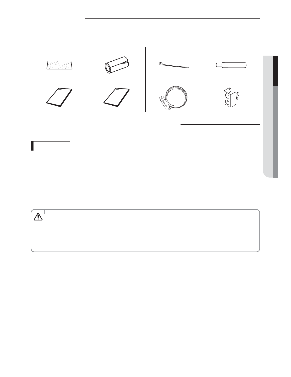
Accessories
The following accessories are supplied with the indoor unit.
The type and quantity may dier depending on the specications.
Insulation cover band Insulation pipe Cable-tie Drain hose
User manual Installation manual Clamp Bushing bracket
Selecting the installation location
Indoor unit
f There must be no obstacles near the air inlet and outlet.
f Install the indoor unit on a ceiling that can support its weight.
f Maintain sucient clearance around the indoor unit.
f Make sure that the water dripping from the drain hose runs away correctly and safely.
f The indoor unit must be installed in this way, that they are out of public access. (Not touchable by the users)
f Rigid wall without vibration.
f Where it is not exposed to direct sunshine.
f Where the air lter can be removed and cleaned easily.
ENGLISH
CAUTION
t As a rule, the unit cannot be installed at a height of less than 2.5m (8.2ft).
t It is possible to install the unit at a height of between 2.2 ~2.5m (7.2~8.2ft) from the ground, if the unit
has a duct with a well dened length [300mm (11.8inch) or more] to avoid fan motor blower contact.
t If you install the cassette or duct type indoor unit on the ceiling with humidity over 80%, you must apply
extra 10mm (0.39 inch) of polyethylene foam or other insulation with similar material on the body of the
indoor unit.
5

Selecting the installation location
Space requirements for indoor unit
59”(1500mm) or more
59”(1500mm) or more
59”(1500mm) or more
59”(1500mm) or more
t The units must be installed according to distances declared, in order to permit accessibility from each
CAUTION
side, either to guarantee correct operation of maintenance or repairing products. The unit’s parts must be
reachable and removable completely under safety condition (for people or things).
t Do not hold the discharge while carrying the indoor unit to avoid the possibility of breakage. You must
hold the hanger plate on the corner and carry the indoor unit.
6
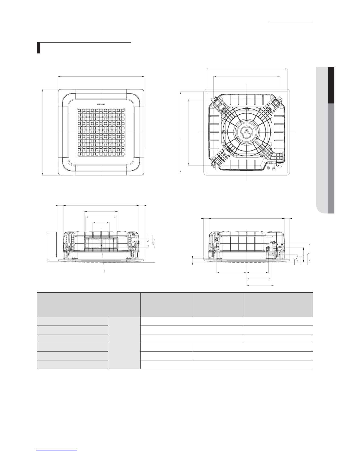
Deciding on where to install the indoor unit
Drawing of the indoor unit
890~910 [35~36 (Celling opening)]
950 (37.4)
950 (37.4)
735 [29 (Suspension position)]
890~910 [35~36 (Celling opening)]
735 [29 (Suspension position)]
Unit : mm (inch)
ENGLISH
55 (2.2) 840 (33)
370 (14.6)
346 (13.6)
185 (7.3)
96 (3.8)
120 (4.7)
AB
Sub duct connection
MODEL
✴009✴
✴018✴
A
55 (2.2) 55 (2.2)840 (33)
45 (1.8)
330 (13) 240 (9.4)
270 (10.6)
300(11.8)
✴030✴
✴024✴
✴036✴
✴048✴
8 (204) 11.3 (288)
B 10 (253) 13.3 (337)
Net dimension 33×8×33 (840×204×840) 33×11.3×33 (840×288×840)
Liquid pipe connection 1/4" (6.35) 3/8" (9.52)
inch (mm)
Gas pipe connection 1/2" (12.7) 5/8" (15.88)
Drain hose connection OD : Ø1.25(32.0), ID : Ø1.04(26.5)
86 (3.4)
164 (6.5)
216 (8.5)
7

Indoor unit installation
It is recommended to install the Y-joint before installing the indoor unit.
1. Place the pattern sheet on the ceiling at the spot where you want to
install the indoor unit.
t Since the diagram is made of paper, it may shrink or stretch
NOTE
slightly due to temperature or humidity. For this reason, before
drilling the holes maintain the correct dimensions between the
markings.
2. Insert bolt anchors, use existing ceiling supports or construct a suitable
support as shown in gure.
3. Install the suspension bolts depending on the ceiling type.
t Ensure that the ceiling is strong enough to support the weight
CAUTION
of the indoor unit. Before hanging the unit, test the strength of
each attached suspension bolt.
t If the length of suspension bolt is more than 1.5m (4.92 ft), it is
required to prevent vibration.
t If this is not possible, create an opening on the false ceiling in
order to be able to use it to perform the required operations on
the indoor unit.
4. Screw eight nuts to the suspension bolts making space for hanging the
indoor unit.
Concrete
Insert
Hole in
anchor
Hole in plug
Suspension bolt [Ø9.52(3/8”) or M10]
Ceiling support
Nut
Washer
t You must install the suspension bolts more than four when
CAUTION
installing the indoor unit.
5. Check the level of the indoor unit by using a leveler.
t A tilt of the indoor unit may cause malfunction of a built-in oat switch
and water leaks.
8
Rubber
Fasten the nut
Level

6. Adjust the height of the indoor unit by using the gauge of dimensions.
t You should adjust the gauge of dimensions and the pattern sheet to t
the cutting dimensions of ceiling.
t Make sure that the indoor unit is installed at a level if the indoor unit
slants too much, there can be water leaks.
Indoor unit
17mm(0.67")
20mm(0.79")
Ceiling
Gauge of
Dimensions
7. Tighten the upper part nuts.
8. Remove the gauge of dimensions after installing the indoor unit.
Purging the unit
From factory the unit is supplied and set with a pre-charge of nitrogen gas. (insert gas) Therefore, all insert gas must be
purged before connecting the assembly piping.
Unscrew the pinch pipe at the end of each refrigerant pipe.
RESULT : All inert gas escapes from the indoor unit.
t To prevent dirt or foreign objects from getting into the pipes
NOTE
during installation, do NOT remove the pinch pipe completely
until you are ready to connect the piping.
Liquid refrigerant port
Gas refrigerant port
ENGLISH
9

Connecting the refrigerant pipe
There are two refrigerant pipes of dierent diameters :
f A smaller one for the liquid refrigerant
f A larger one for the gas refrigerant
f The inside of copper pipe must be clean & has no dust
1. Remove the pinch pipe on the pipes and connect the assembly pipes to each pipe, tightening the nuts, rst
manually and then with a torque wrench, a spanner applying the following torque.
Refrigerant oil
t If the pipes must be shortened refer to page 11.
NOTE
Torque
wrench
Flare nut
Spanner
Union
2. Must use insulator which is thick enough to cover the refrigerant tube to
protect the condensate water on the outside of pipe falling onto the oor and
the eciency of the unit will be better.
3. Cut o any excess foam insulation.
Outer Diameter Torque
mm inch /tN MCGtGU
6.35 1/4 14~18 10.3~13.3
9.52 3/8 34~42 25.1~31.0
12.70 1/2 49~61 36.1~45.0
15.88 5/8 68~82 50.2~60.5
4. Be sure that there must be no crack or wave on the bended area.
5. It would be necessary to double the insulation thickness(10mm or more) to prevent condensation even on the
insulator when if the installed area is warm and humid.
6. Do not use joints or extensions for the pipes that connect the indoor and outdoor unit. The only permitted
connections are those for which the units are designed.
t Connect the indoor and outdoor units using pipes with ared connections(not supplied). For the lines,
CAUTION
use insulated, unwelded, degreased and deoxidized copper pipe,(Cu DHP type to ISO 1337), suitable for
operating pressures of at least 4200kPa(609.2 psi) and for a burst pressure of at least 20700kPa(3002.3 psi).
Copper pipe for hydro-sanitary applications is completely unsuitable.
t For sizing and limits (height dierence, line length, max. bends, refrigerant charge, etc.) see the outdoor
unit installation manual.
t All refrigerant connection must be accessible, in order to permit either unit maintenance or removing it
completely.
10
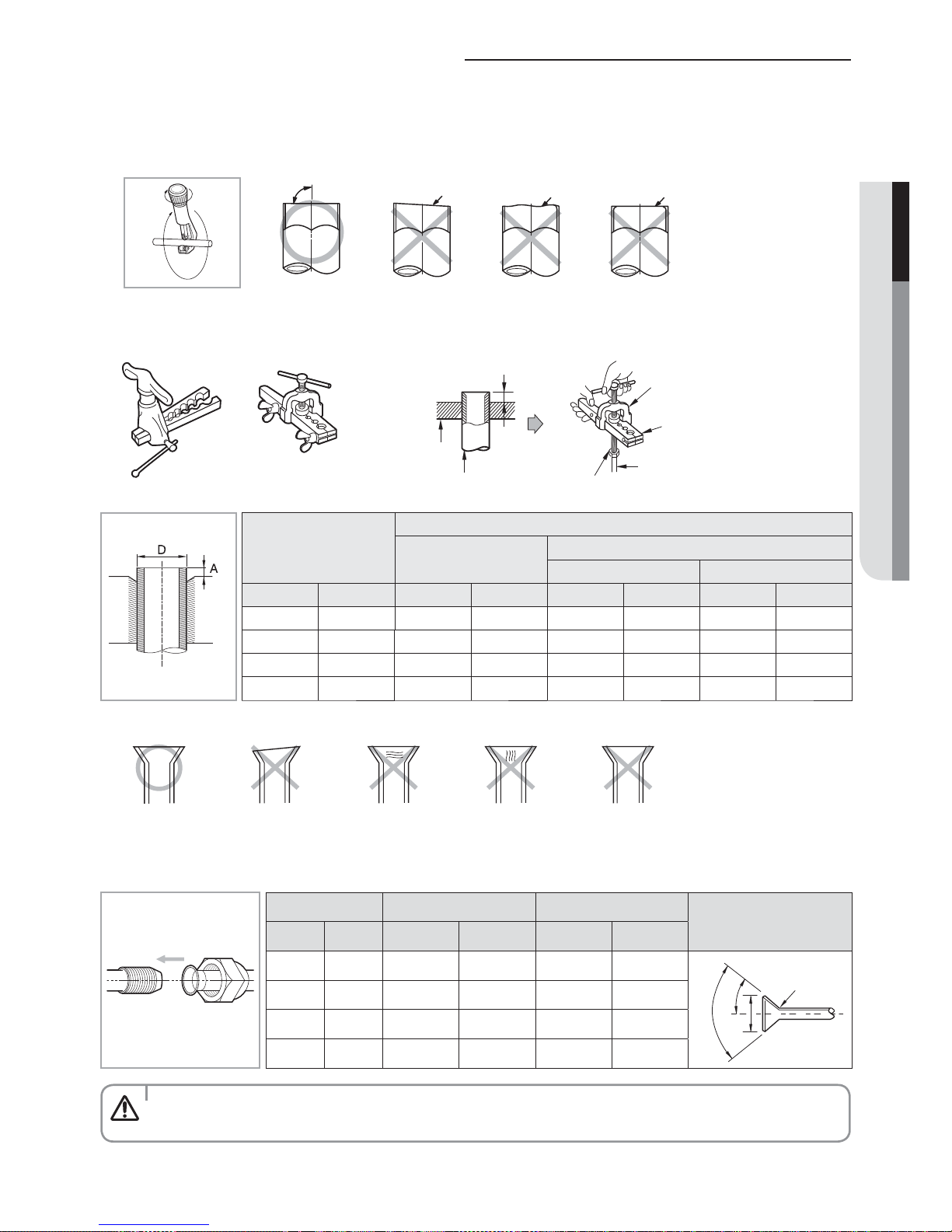
Cutting/aring the pipes
1. Make sure that you prepared the required tools. (pipe cutter, reamer, aring tool and pipe holder)
2. If you want to shorten the pipe, cut it using a pipe cutter ensuring that the cut edge remains at 90° with the side of
the pipe. There are some examples of correctly and incorrectly cut edges below.
90°
Oblique
3. To prevent a gas leak, remove all burrs at the cut edge of the pipe using a reamer.
4. Carry out aring work using aring tool as shown below.
Rough
Burr
ENGLISH
Flaring tool
Clutch type Wing nut type
Outer diameter (D)
mm inch mm inch mm inch mm inch
6.35 1/4 0~0.5 0~0.02 1.0~1.5 0.04~0.06 1.5~2.0 0.06~0.08
9.52 3/8 0~0.5 0~0.02 1.0~1.5 0.04~0.06 1.5~2.0 0.06~0.08
12.70 1/2 0~0.5 0~0.02 1.0~1.5 0.04~0.06 1.5~2.0 0.06~0.08
15.88 5/8 0~0.5 0~0.02 1.0~1.5 0.04~0.06 1.5~2.0 0.06~0.08
Die
Copper pipe
Using aring tool for
R-410A
A
Yor k
Die
Copper pipe
Flare nut
Depth of aring part (A)
Using conventional aring tool
Clutch type Wing nut type
5. Check if you ared the pipe correctly. There are some examples of incorrectly ared pipes below.
Correct Inclined Damaged Surface Cracked Uneven Thickness
6. Align the pipes and tighten the are nuts rst manually and then with a torque wrench, applying the following
torque.
Outer diameter Connection Torque Flare dimension
mm inch N·m Ibf·ft mm inch
6.35 1/4 14~18 10.3~13.3 8.7~9.1 0.34~0.36
9.52 3/8 34~42 25.1~31.0 12.8~13.2 0.50~0.52
12.70 1/2 49~61 36.1~45.0 16.2~16.6 0.64~0.65
15.88 5/8 68~82 50.2~60.5 19.3~19.7 0.76~0.78
t In case of needing brazing, you must work with Nitrogen gas blowing.
CAUTION
Flare shape [mm(inch)]
R 0.4~0.8
(0.016~0.032)
±2°
45°
90° ±2°
11

Performing leak test & insulation
Leak test
LEAK TEST WITH NITROGEN (before opening valves)
In order to detect basic refrigerant leaks, before recreating the vacuum and
recirculating the R-410A, it’s responsible of installer to pressurize the whole
system with nitrogen (using a pressure regulator) at a pressure above 4.1MPa
[594.7 psig (gauge)].
LEAK TEST WITH R-410A (after opening valves)
Before opening valves, discharge all the nitrogen into the system and create
vacuum. After opening valves check leaks using a leak detector for refrigerant
R-410A.
CAUTION
Insulation
Once you have checked that there are no leaks in the system, you can insulate the piping and hose.
t Discharge all the nitrogen to create a vacuum and charge the system.
1. To avoid condensation problems, place T13.0 (1/2”) or thicker
Acrylonitrile Butadien Rubber separately around each refrigerant pipe.
t Always make the seam of pipes face upwards.
NOTE
2. Wind insulating tape around the pipes and drain hose avoiding to
compress the insulation too much.
3. Finish wrapping insulating tape around the rest of the pipes leading to
the outdoor unit.
4. The pipes and electrical cables connecting the indoor unit with the
outdoor unit must be xed to the wall with suitable ducts.
NBR[T13.0 (1/2”) or thicker]
Indoor unit
No gap
Insulation cover pipe
Insulation pipe
Be sure to overlap
the insulation
t All refrigerant connection must be accessible, in order to permit either unit maintenance or removing it
CAUTION
completely.
12
t Must t tightly against
CAUTION
body without any gap.
 Loading...