

Samsung AM007FNTDCH Installation Manual


2
A
Contents
Safety precautions ......................................................................................................................................................3
Accessories ....................................................................................................................................................................5
Selecting the installation location ..........................................................................................................................6
Indoor unit installation .............................................................................................................................................7
Purging the unit ..........................................................................................................................................................8
Connecting the refrigerant pipe .............................................................................................................................9
Cutting/aring the pipes ........................................................................................................................................ 10
Performing leak test & insulation ........................................................................................................................ 11
Drain hose installation ............................................................................................................................................ 12
Charging direction of the drain hose ................................................................................................................. 13
Wiring work ............................................................................................................................................................... 14
Setting an indoor unit address and installation option ................................................................................. 17
Final check and trial operation ............................................................................................................................. 28
Providing information for user ............................................................................................................................. 28
Troubleshooting ....................................................................................................................................................... 28
Connecting power and communication cable ................................................................................................. 30
INSTALLATION PARTS
3
A
Safety precautions
(Carefully follow the precautions listed below because they are essential to guarantee the safety of the
equipment.)
WARNING
xAlways disconnect the air conditioner from the power supply before servicing it or
accessing its internal components.
x
Verify that installation and testing operations are performed by qualified personnel.
xVerify that the air conditioner is not installed in an easily accessible area.
GENERAL INFORMATION
X Carefully read the content of this manual before installing the air conditioner and store the manual in a safe place in
order to be able to use it as reference after installation.
X For maximum safety, installers should always carefully read the following warnings.
X Store the operation and installation manual in a safe location and remember to hand it over to the new owner if the
air conditioner is sold or transferred.
X This manual explains how to install an indoor unit with a split system with two SAMSUNG units. The use of other types
of units with different control systems may damage the units and invalidate the warranty. The manufacturer shall not
be responsible for damages arising from the use of non compliant units.
X
The manufacturer shall not be responsible for damage originating from unauthorized changes or the improper connection
of electric and hydraulic lines. Failure to comply with these instructions or to comply with the requirements set forth in the
“Operating limits” table, included in the manual, shall immediately invalidate the warranty.
X The air conditioner should be used only for the applications for which it has been designed: the indoor unit is not
suitable to be installed in areas used for laundry.
X Do not use the units if damaged. If problems occur, switch the unit off and disconnect it from the power supply.
X In order to prevent electric shocks, fires or injuries, always stop the unit, disable the protection switch and contact
SAMSUNG’s technical support if the unit produces smoke, if the power cable is hot or damaged or if the unit is very
noisy.
X Always remember to inspect the unit, electric connections, refrigerant tubes and protections regularly.
These operations should be performed by qualified personnel only.
X The unit contains moving parts, which should always be kept out of the reach of children.
X Do not attempt to repair, move, alter or reinstall the unit. If performed by unauthorized personnel, these operations
may cause electric shocks or fires.
X Do not place containers with liquids or other objects on the unit.
X
All the materials used for the manufacture and packaging of the air conditioner are recyclable.
X The packing material and exhaust batteries of the remote control(optional) must be disposed of in accordance with
current laws.
X The air conditioner contains a refrigerant that has to be disposed of as special waste. At the end of its life cycle, the air
conditioner must be disposed of in authorized centers or returned to the retailer so that it can be disposed of correctly
and safely.
INSTALLING THE UNIT
IMPORTANT: When installing the unit, always remember to connect first the refrigerant tubes, then the electrical lines.
Always disassemble the electric lines before the refrigerant tubes.
X Upon receipt, inspect the product to verify that it has not been damaged during transport. If the product appears
damaged, DO NOT INSTALL it and immediately report the damage to the carrier or retailer (if the installer or the
authorized technician has collected the material from the retailer.)
X After completing the installation, always carry out a functional test and provide the instructions on how to operate
the air conditioner to the user.
X Do not use the air conditioner in environments with hazardous substances or close to equipment that release free
flames to avoid the occurrence of fires, explosions or injuries.
X The air conditioner should be used only for the applications for which it has been designed: the indoor unit is not
suitable to be installed in areas used for laundry.
4
A
X Our units must be installed in compliance with the spaces indicated in the installation manual to ensure either
accessibility from both sides or ability to perform routine maintenance and repairs. The units’ components must be
accessible and that can be disassembled in conditions of complete safety either for people or things.
For this reason, where it is not observed as indicated into the Installation Manual, the cost necessary to reach and repair
the unit (in safety, as required by current regulations in force) with slings, trucks, scaffolding or any other means of
elevation won’t be considered in-warranty and charged to end user.
POWER SUPPLY LINE, FUSE OR CIRCUIT BREAKER
X Always make sure that the power supply is compliant with current safety standards. Always install the air conditioner in
compliance with current local safety standards.
X Always verify that a suitable grounding connection is available.
X Verify that the voltage and frequency of the power supply comply with the specifications and that the installed power is
sufficient to ensure the operation of any other domestic appliance connected to the same electric lines.
X Always verify that the cut-off and protection switches are suitably dimensioned.
X Verify that the air conditioner is connected to the power supply in accordance with the instructions provided in the
wiring diagram included in the manual.
X Always verify that electric connections (cable entry, section of leads, protections…) are compliant with the electric
specifications and with the instructions provided in the wiring scheme. Always verify that all connections comply with
the standards applicable to the installation of air conditioners.
X Make sure that you earth the cables.
- Do not connect the earth wire to the gas pipe, water pipe, lighting rod or telephone wire.
If earthing is not complete, electric shock or fire may occur.
X
Install the circuit breaker.
- If the circuit breaker is not installed, electric shock or fire may occur.
X
Make sure that the condensed water dripping from the drain hose runs out properly and safely.
X Install the power cable and communication cable of the indoor and outdoor unit at least 1m
away from the electric appliance.
X
Install the indoor unit away from lighting apparatus using the ballast.
- If you use the wireless remote control, reception error may occur due to the ballast of the
lighting apparatus.
X
Do not install the air conditioner in following places.
- Place where there is mineral oil or arsenic acid.
Resin parts flame and the accessories may drop or water may leak.
The capacity of the heat exchanger may reduce or the air conditioner may be out of order.
- The place where corrosive gas such as sulfurous acid gas generates from the vent pipe or air
outlet.
The copper pipe or connection pipe may corrode and refrigerant may leak.
- The place where there is a machine that generates electromagnetic waves.
The air conditioner may not operate normally due to control system.
- The place where there is a danger of existing combustible gas, carbon fiber or flammable
dust.
The place where thinner or gasoline is handled.
Gas may leak and it may cause fire.
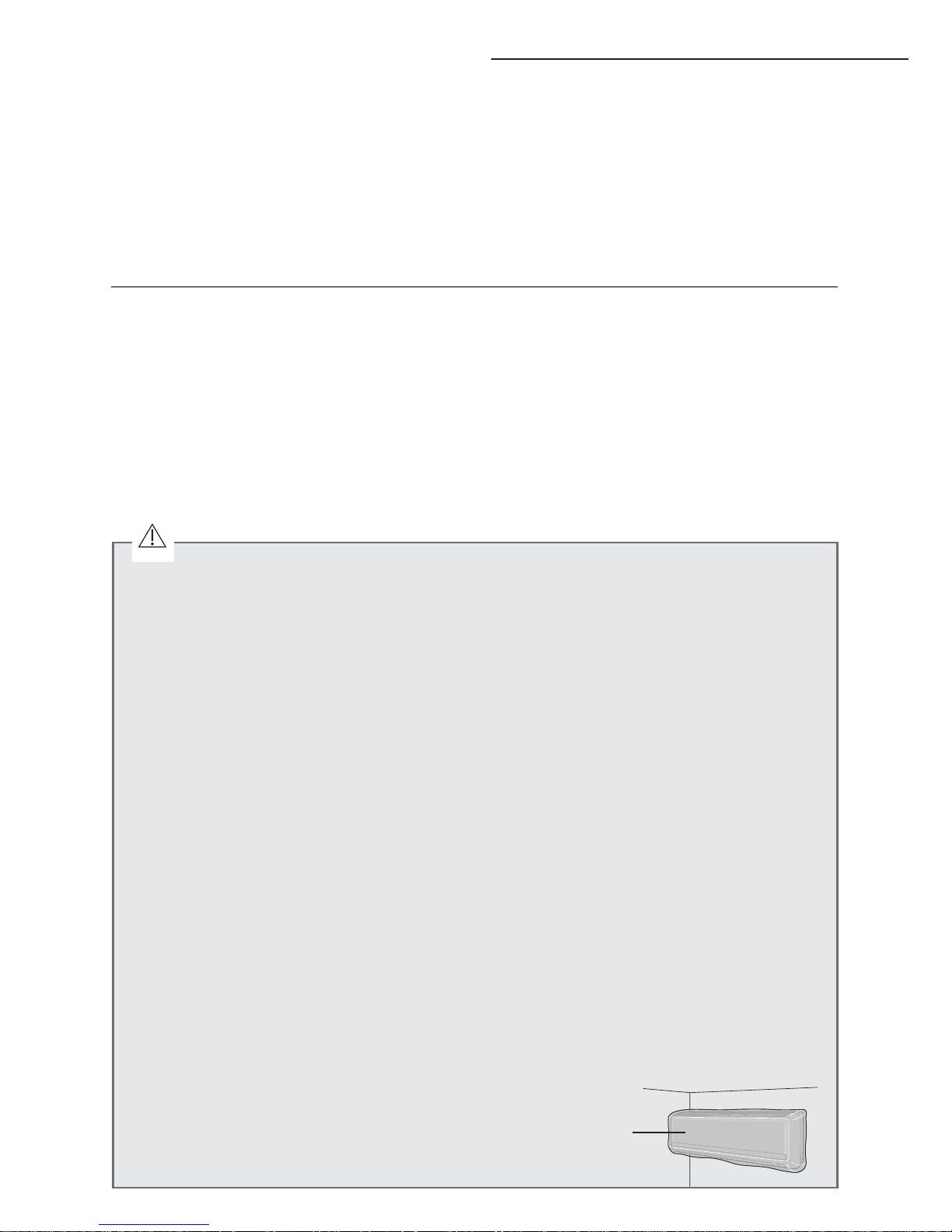
X
Please cover the air conditioner with PE BAG after installation,and remove it when you start
to run air conditioner.
Safety precautions
CAUTION
PE BAG
5
A
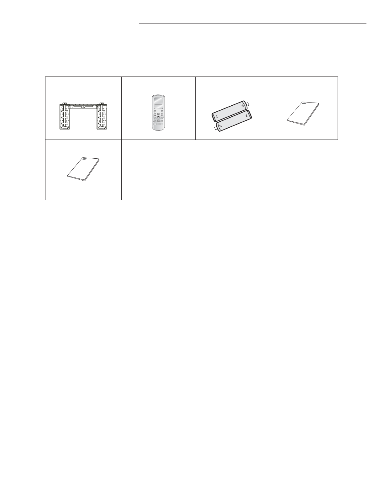
Accessories
The following accessories are supplied with the indoor unit.
The type and quantity may differ depending on the specifications.
Installation Plate Remote Control Batteries for
Remote Control
Installation manual
User's manual
6
A
Selecting the installation location
Indoor Unit
X
Where airflow is not blocked.
X
Where cool air can be distributed throughout the room.
X
Install the refrigerant piping length and the height difference of both indoor and outdoor units as
indicated in the installation diagram.
X
Wall that prevents vibration and is strong enough to hold the product weight.
X
Out of the direct sunlight .
X
1m or more away from the TV or radio (to prevent the screen from being distorted or noise from being
generated).
X
As far away as possible from fluorescent and incandescent lights (so that the remote control can be
operated well).
X
A place where the air filter can be replaced easily.
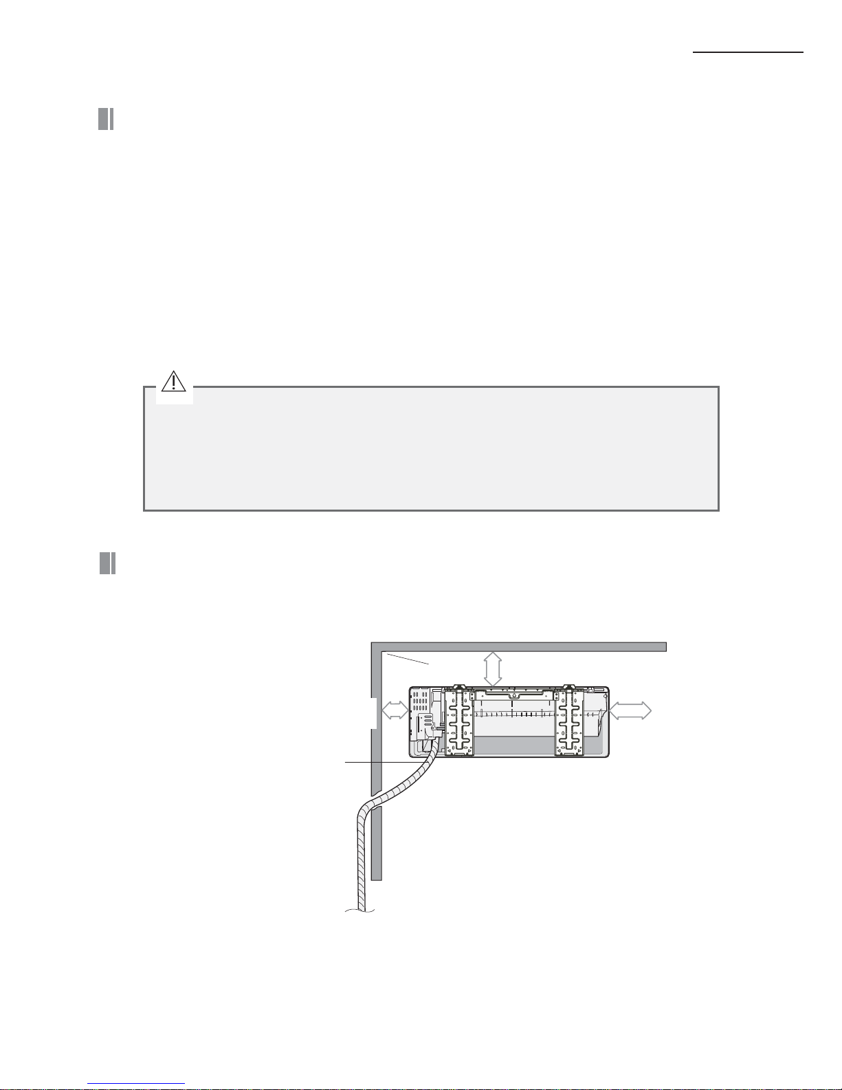
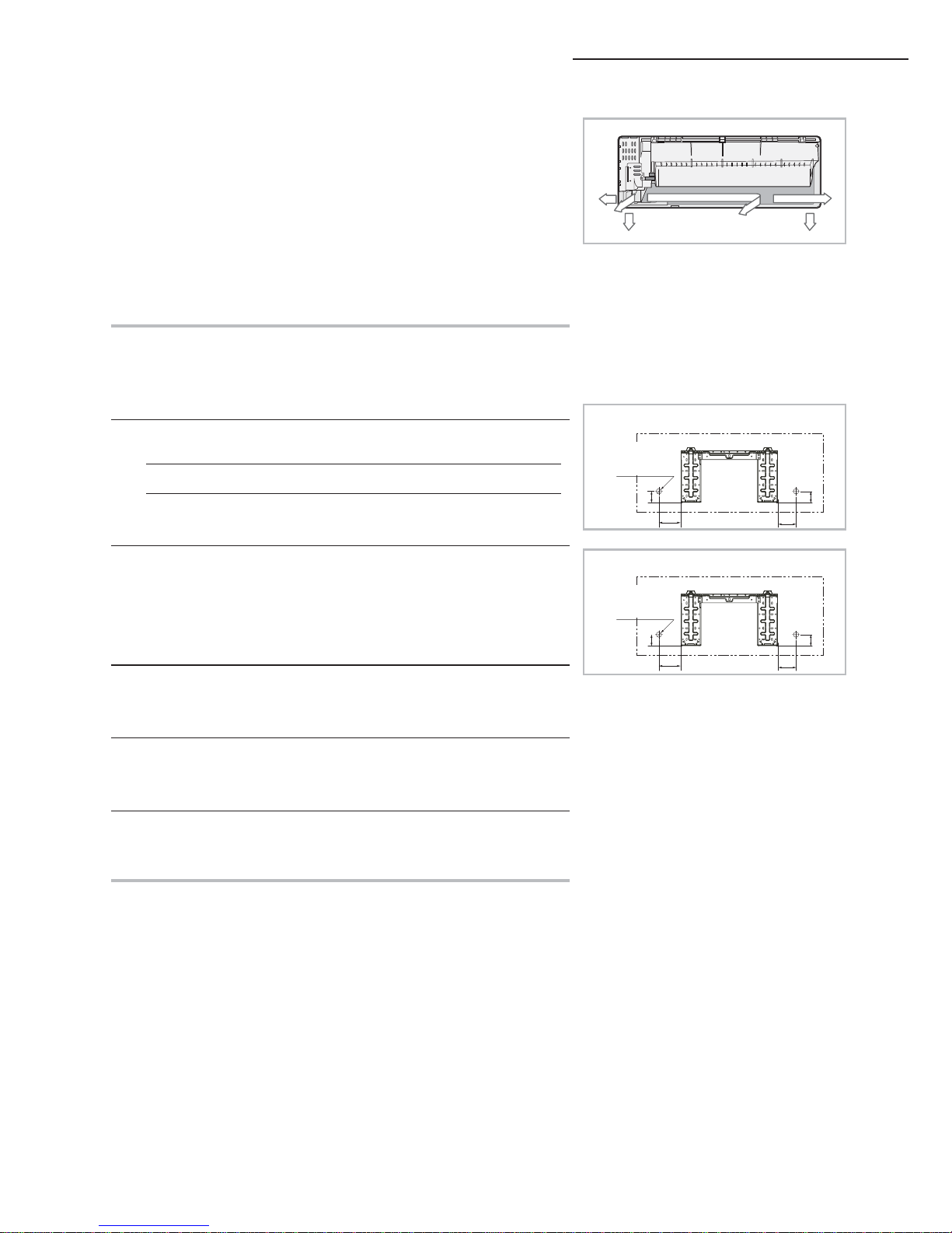
Space requirements for installation & service
Observe the clearances and maximum lengths as seen in the picture below when installing the
air conditioner.
125 mm
or more
100 mm or more
125 mm
or more
Wrap the refrigerant pipes and the drain
hose with the absorbent pad and vinyl
tape. Refer to page 17 for further details.
You can select the direction
of draining. (left or right)
KThe appearance of the unit may be different from the diagram depending on the model.
X Avoid the following places to prevent malfunction of the unit
- Where there is machine oil
- Salty environment such as the seaside areas
- Where sulfide gas exists
- Other special atmosphere areas
CAUTION
7
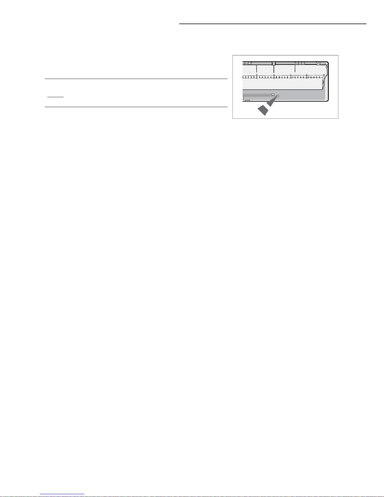
A
Before fixing the installation plate to the wall or window frame,
you must determine the position of the 65mm hole through which
the cable, pipe and hose pass to connect the indoor unit to the
outdoor unit.
When facing the wall, the pipe and cable can be connected from
the:
X Right
X Left
X Underside (right)
X Rear (right or left)
1
Determine the position of the pipe and drain hose hole as seen in
the picture and drill the hole with an inner diameter of 65mm so
that it slants slightly downwards.
2
If you fix the indoor unit to a... Follow step(s)...
Wall 3.
Window frame 4 to 6.
3 Fix the installation plate to the wall giving attention to the weight
of the indoor unit.
± If you mount the plate to a concrete wall with anchor bolts,
the anchor bolts must not project more than 20mm.
4 Determine the positions of the wooden uprights to be attached to
the window frame.
5 Attach the wooden uprights to the window frame giving attention
to the weight of the indoor unit.
6 Attach the installation plate to the wooden uprights using tapping
screws as seen in the picture.
120
72
68
72
(Unit : mm)
77015/022/028/03677
Pipe hole
(Ø65mm)
140
34
68
34
(Unit : mm)
77045/056/07177
Pipe hole
(Ø65mm)
Indoor unit installation
8
A
Purging the unit
Upon delivery, there may be inert gas inside the indoor unit.
Purge the gas from the indoor unit before connecting the
assembly pipe.
Unscrew the caps at the end of each pipe.
Result: All inert gas exhausts from the indoor unit.
±
To prevent dirt or foreign substances from getting into the
pipes during installation, do NOT remove the caps
completely until you are ready to connect the pipes.
9
Connecting the refrigerant pipe
There are 2 refrigerant pipes of different diameters:
X The smaller one is for the liquid refrigerant
X The larger one is for the gas refrigerant
A short pipe is already fitted to the air conditioner. You may need to
extend the pipe using the assembly pipe. (optional)
The connection procedure for the refrigerant pipe varies according to the
exit position of the pipe when facing the wall:
X Right(A)
X Left(B)
X Underside(C)
X Rear
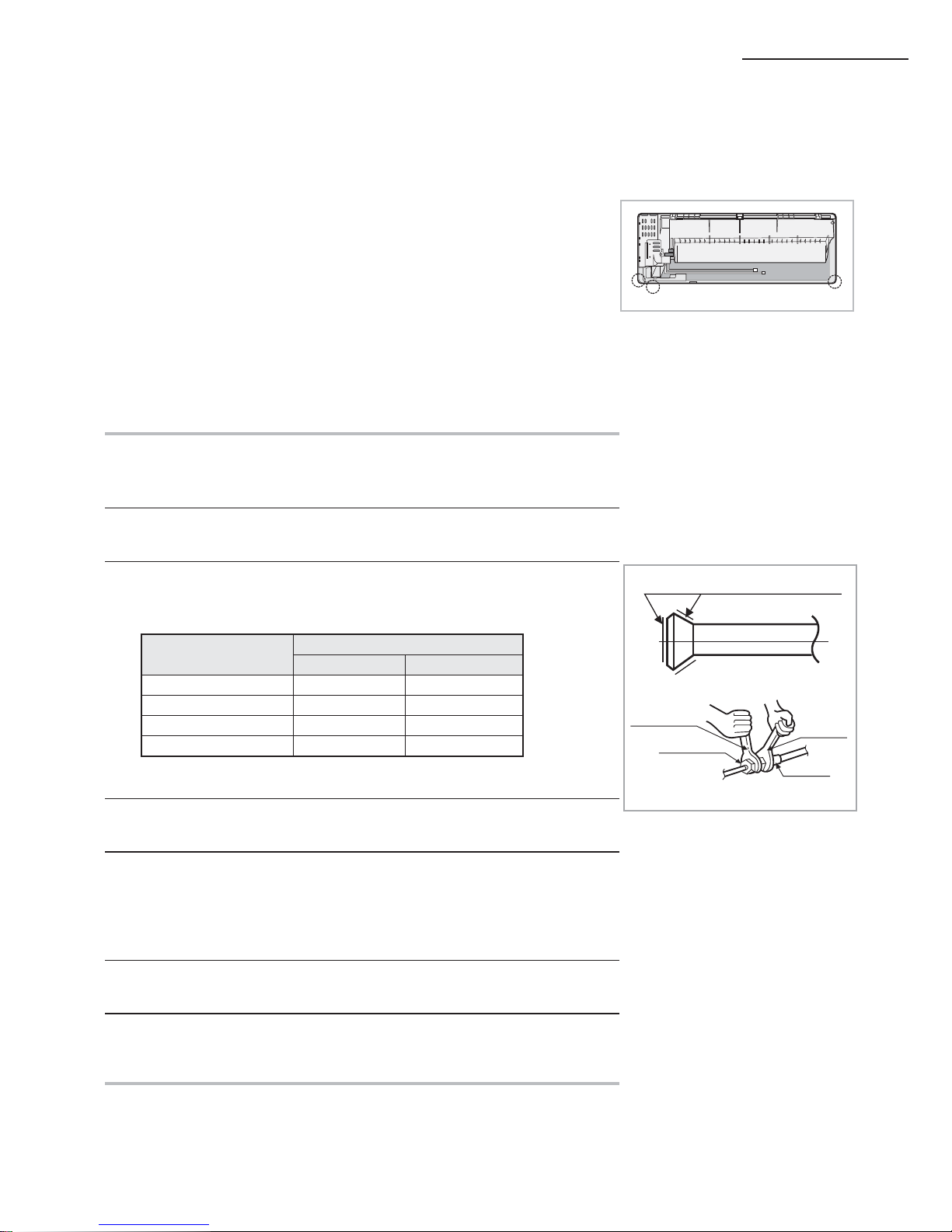
1
Cut out the appropriate knock-out piece on the rear of the indoor unit
unless you connect the pipe directly from the rear.
2 Smooth the cut edges.
3 Remove the protection caps of the pipes and connect the assembly pipe
to each pipe. Tighten the nuts first with your hands, and then with a torque
wrench, applying the following torque:
Outer Diameter
Torque
LHGtDN /tN
6.35 mm 140~180 14~18
9.52 mm 350~430 34~42
12.70 mm 500~620 49~61
15.88 mm 690~830 68~82
± If you want to shorten or extend pipes, refer to page 10.
4 Cut off the remaining foam insulation.
5 If necessary, bend the pipe to fit along the bottom of the indoor unit.
Then pull it out through the appropriate hole.
X The pipe should not project from the rear of the indoor unit.
X The bending radius should be 100 mm or more.
6 Pass the pipe through the hole in the wall.
7 For further details on how to connect to the outdoor unit and purge the air,
refer to page 8.
±
±
The pipe will be insulated and fixed permanently into position after
finishing the installation and the gas leak test; refer to page 17 for
further details.
DO NOT WALL UP THE PIPE CONNECTION !
All refrigerant pipe connection must be easy accessible and serviceable.
B
A
C
Connect indoor and outdoor units with field-supplied copper pipes by
means of flare connections. Use insulated seamless refrigeration grade
pipe only, (Cu DHP type according to ISO1337), degreased and deoxidized,
suitable for operating pressures of at least 4200 kPa and for burst pressure
of at least 20700 kPa. Under no circumstances must sanitary type copper
pipe be used.
Refrigerant oil
Torque wrench
Flare nut
Union
Spanner
10
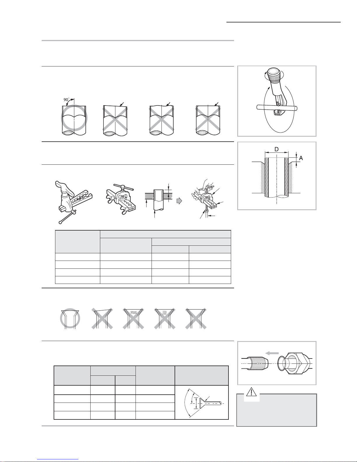
Cutting/aring the pipes
1
Make sure that you prepared the required tools.
(pipe cutter, reamer, flaring tool and pipe holder)
2
If you want to shorten the pipe, cut it using a pipe cutter ensuring that
the cut edge remains at 90° with the side of the pipe. There are some
examples of correctly and incorrectly cut edges below.
Oblique Rough Burr
3
To prevent a gas leak, remove all burrs at the cut edge of the pipe using a
reamer.
4
Carry out flaring work using flaring tool as shown below.
Flaring tool
Clutch type Wing nut type
A
Die
Copper pipe
Yo rk
Die
Copper
pipe
Flare nut
Outer diameter
(mm)
A(mm)
Flare tool for
R410A clutch type
Conventional flare tool
Clutch type Wing nut type
6.35
0~0.5 1.0~1.5 1.5~2.0
9.52
0~0.5 1.0~1.5 1.5~2.0
12.70
0~0.5 1.0~1.5 1.5~2.0
15.88
0~0.5 1.0~1.5 1.5~2.0
5
Check if you flared the pipe correctly. There are some examples of
incorrectly flared pipes below.
6
Align the pipes and tighten the flare nuts first manually and then with a
torque wrench, applying the following torque.
Inclined Damaged Surface Cracked Uneven Thickness
In case of needing brazing,
you must work with Nitrogen
gas blowing.
Outer diameter
(mm)
Connection Torque
Flare dimension
(mm)
Flare shape
(mm)
LHGtDN /tN
6.35 140~180 14~18 8.70 ~9.10
R 0.4~0.8
90° ±2°
45°
±2°
9.52 350~430 34~42 12.80~13.20
12.70 500~620 49~61 16.20~16.60
15.88 690~830 68~82 19.30~19.70
CAUTION
 Loading...