

Page 1
Alignment and Adjustments
Samsung Electronics 2-1
2. Alignment and Adjustments
2-1 Service Mode
2-1-1 SERVICE MODE Entry Method (General Transmitter)
▶ Using the Customer Remote
1. Turn the power off and set to stand-by mode.
2. Press the remote buttons in this order; POWER OFF-INFO-MENU-MUTE-POWER ON to turn the set on.
3. The set turns on and enters service mode.
▶ Using the Factory Remote
1. Turn the power on.
2. Press the remote buttons in this order : Display-Factory.
3. The set enters service mode.
* If you fail to enter service mode, repeat steps 1 and 2 above.
2-1-2 Initial SERVICE MODE DISPLAY State
2-1-2(A) OSD DISPLAY
2-1-2(B) Button Operations in SERVICE MODE
* While in Tuner mode, the direct access buttons can be used to select and change channels.
☞ Indicates selected input mode
☞ Picture Adjustment
☞ Setting the Initial Values
☞ Setting the Special Features
☞ Options-1 : Particulars Product Options
☞ Options-2 : PDP Properties Options
☞ Initializing after saving the adjustments
☞ Software Version Information
Factory Mode Current Input Mode
01. Picture Improvement ▶
02. Initial Setting ▶
03. PIP/TTX/Test Pattern ▶
04. Option-1 ▶
05. Option-2 ▶
06. Reset ▶
Release : 2004-05-20-16:30
Version : T-NELPCI-1029
Menu Displays all menus
UP/DOWN Cursor moves to select items
LEFT/RIGHT To increase and decrease the data of the selected items
(ENTER) Confirm your choice(Store OR Enter)
TV/VIDEO Button Change input source
Page 2
Alignment and Adjustments
2-2 Samsung Electronics
2-2 WHITE Balance Coordinates
2-2-1 PS42D4S/PS42V4S White Balance Adjustment
1. W/B Adjustment is required for the following six modes :
DVI -> Component(720p) -> Component(1080i) -> PC -> VIDEO (Video port) -> VIDEO (Graphic port)
2. Adjustment Method (Signal equipment : MSPG-925LTH, Measurement equipment : CA210)
■ MSPG-925LTH
Equipment that outputs analog and digital signals simultaneously
(Analog / Digital signal output / TV signal output (S-Video included) / HDTV signal output)
-. Digital Serial : TMDS (DVI24, SiI160) + DVI-I (Analog, Digital)
-. Monitor Signal (Analog): R, G, B, HS, VS, CS
-. TV Signal(CVBS) : NTSC M, NTSC J (7.5 IRE On/Off) (BNC or RCA), PAL B, D, G, H, I, PAL M, Nc
-. D-TV Signal (1080i, 720p, 480p)
♣ MSPG-925 is used to adjust the W/B.
■ CA210 : Color Analyzers adjusting brightness, chromaticity and etc.
-. R.G.B monochrome correction, brightness and gamma character adjustment
-. White Balance and flickering measurement
(a) DVI
1) Input Toshiba Pattern at 720p resolution using MSPG-925LTH (model:#6, pattern:#16).
2) These are the point of measurement using CA210.
3) Press "POWER OFF-INFO-MENU-MUTE-POWER ON" to enter the factory mode.
4) Select "01.Picture Improvement" -> "01.White Balance"
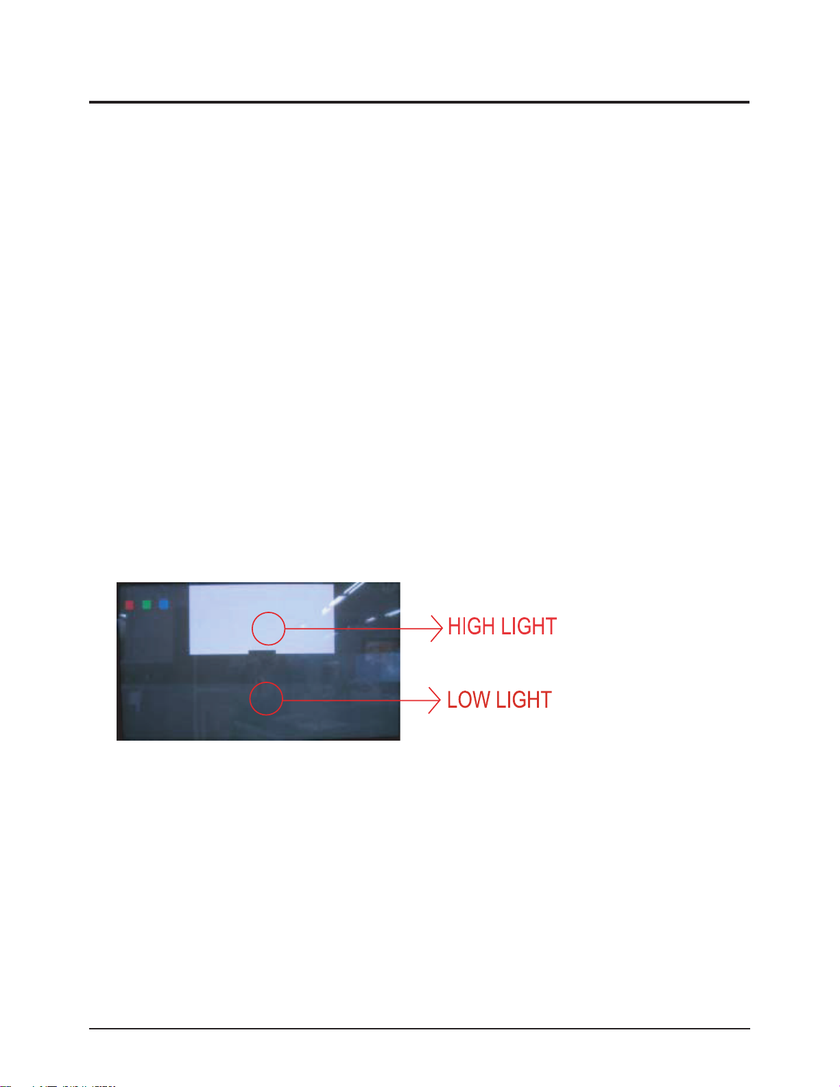
5) Keep the value of Y as adjusting "07.Sub Contrast(for HIGH)" & "08.Sub Brightness(for LOW) ".
6) Keep the coordinate value of x and y as adjusting the value of R,G,B.
Adjust the coordinate x as the value of Red, and the coordinate y as the value of Blue.
<※ Generally, the value of Green is fixed.>
-. Adjust the value of "Drive(01~03)" as the high point and the value of "Cutoff(04~06)" as low point.
Page 3
Alignment and Adjustments
Samsung Electronics 2-3
※ Auto Color
-. Must be executed in Component/PC before adjusting White Balance.
1) Input Auto Color Pattern with MSPG-925LTH(model:#6, pattern:#21).
2) Press "POWER OFF-INFO-MENU-MUTE-POWER ON" to enter the factory mode.
3) Select "01.Picture Improvement" ¡æ "01.White Balance" -> "15.Auto Color"
and Select "Off" -> "On"
4) It takes a few seconds to execute it.
(b) Component
1) Execute Auto Color in the method described above.
2) Input Toshiba Pattern at 720p resolution (model:#6, pattern:#16).
3) Select "01.Picture Improvement" -> "01.White Balance".
4) Adjust White Balance by selecting and adjusting Items 01. - 08. as performed in DVI mode.
5) Change input to Toshiba Pattern at 1080i resolution (model:#5, pattern:#16).
6) Adjust White Balance by selecting and adjusting Items 01. - 08. as performed in DVI mode.
(c) PC
1) Execute Auto Color in the method described above.
2) Input Toshiba Pattern at 800 x 600 (model:#16, pattern:#16).
3) Select "01.Picture Improvement" -> "01.White Balance".
4) Adjust White Balance by selecting and adjusting Items 01 - 08 as performed in DVI mode.
(d) Video
The video signal uses the video port when there is no other input signal.
However, signal uses the graphic port in PIP mode, which includes other input signals (PC, DVI, Component, etc.), Video adjust-
ment should be performed with Video port and Graphic port separately.
1) Input Toshiba Pattern to Video Input (model:#2, pattern:#16).
2) Select "04.Option-1" -> "10.Video Port."
3) Set "10. Video Port" equal to "Video".
4) At Main SVC Menu, select "01.Picture Improvement" -> "01.White Balance."
5) Adjust Items 01 - 08 as performed in DVI mode.
6) Return to Main SVC menu and select "04.Option-1" -> "10.Video Port."
7) Set "10. Video Port" equal to "Graphic".
Page 4
H/L
L/L
x
y
Y(fL)
x
y
Y(fL)
VIDEO
285
295
36
285
295
0.6
Component
285
295
31
285
295
0.7
PC(D4 ONLY)
278
285
38
280
295
0.6
DVI
280
295
36
280
295
1.8
2-2-2 White Balance Coordinates by Mode(Europe)
Alignment and Adjustments
2-4 Samsung Electronics
8) At Main SVC Menu, select "01.Picture Improvement" -> "01.White Balance".
9) Adjust Items 01 -> 08 as performed in DVI Mode.
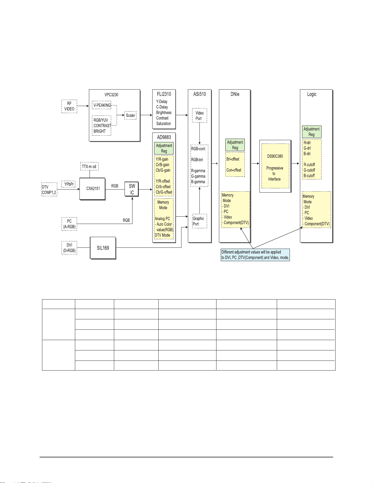
* Thus, Micom saves the W/B data separately for each memory mode of the block (See the block diagram given below) during
W/B adjustment.
Page 5
Alignment and Adjustments
Samsung Electronics 2-5
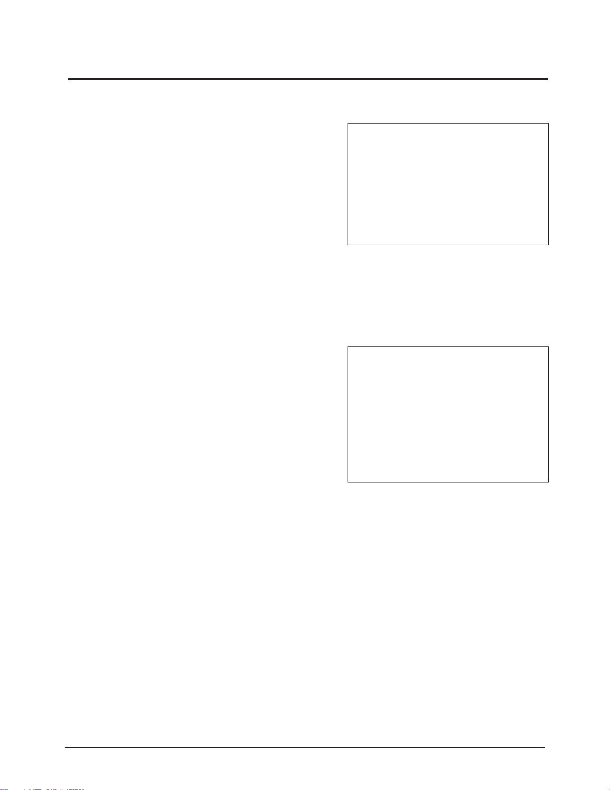
2-3-1 Factory OSD Main Menu
2-3 Factory Data
☞ Indicates selected input mode
☞ Picture Adjustment
☞ Setting the Initial Values
☞ Setting the Special Features
☞ Setting PDP Properties Options
☞ Setting PDP Properties Options
☞ Initializing after saving the adjustments
☞ Software Version Information
01.Picture Improve
Factory Mode Current Input Mode
01. Picture Improvement ▶
02. Initial Setting ▶
03. PIP/TTX/Test Pattern ▶
04. Option-1 ▶
05. Option-2 ▶
06. Reset ▶
Release : 2004-05-20-16:30
Version : T-NELPCI-1029
☞ White Balance Adjustment
☞ Color Adjustment
☞ Contrast & Brightness Enhancement
☞ Detail Enhancement Sharpness Adjustment
☞ Y/C Delay Setting according to the System and
Input Modes
☞Motion Enhancing Adjustment
☞ DNIe Registers
☞ Logic Registers of the Panel
☞ Picture Size Registers
01.Picture Improvement Current Input Mode
01. White Balance ▶
02. Color ▶
03. Cont/Bri Enhancement ▶
04. Detail Enhancement ▶
05. Y/C Delay ▶
06. Motion ▶
07. DNIe ▶
08. Logic ▶
09. Picture Size ▶
Page 6
Alignment and Adjustments
2-6 Samsung Electronics
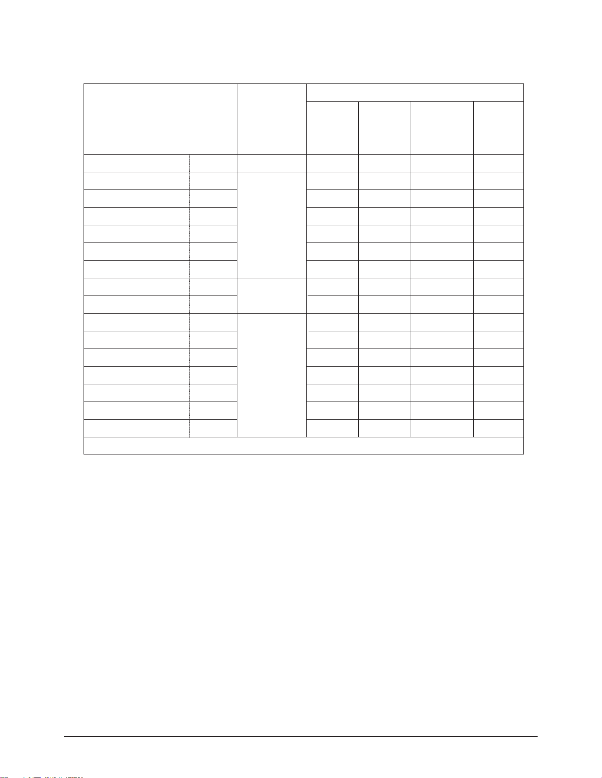
01.Picture Improve => 01.White Balance Adjustment
01.White Balance
01.R Drive
02.G Drive
03.B Drive
04.R Cutoff
05.G Cutoff
06.B Cutoff
07.Sub Contrast
08.Sub Brightness
09.R Gain
10.G Gain
11.B Gain
12.R/Cr Offset
13.G/Y Offset
14.B/Cb Offset
15.Auto color
TV
140
130
120
128
128
128
37
54
142
142
142
60
48
64
on/off
Mode-1
140
130
120
128
128
128
37
54
X
X
X
X
X
X
X
Initial Values of Input Modes
Video
Component
PC(D4 ONLY)
DVI
Relevant IC
Logic
DNIe
AD9883
ITEM
♣ Input modes require respective storing the changes after adjustment.
01~06 : Logic
07~08 : DNIe
09~15 : AD9883
Mode-2
140
130
120
128
128
128
37
54
128
150
128
60
48
64
O
Mode-4
140
130
120
128
128
128
37
54
X
X
X
X
X
X
X
Mode-3
140
130
120
128
128
128
37
54
128
128
128
60
48
64
O
Page 7
Alignment and Adjustments
Samsung Electronics 2-7
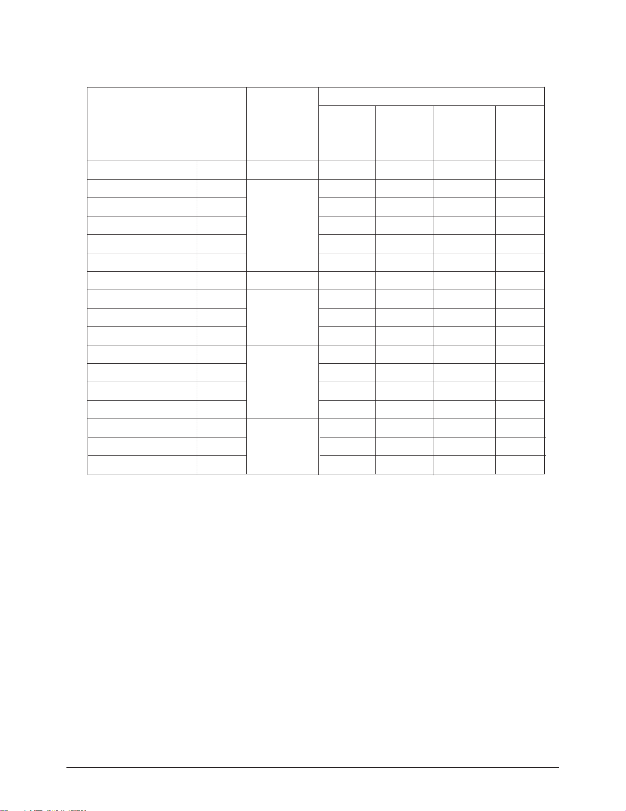
01.Picture Improve => 02.Color Adjustment
02.Color
01.Saturation
02.Tint
03.RGB/YUV U-SAT
04.RGB/YUV V-SAT
05.RGB/YUV Tint
06.FLI-saturation
07.R Gamma
08.G Gamma
09.B Gamma
10.Gain-Sel
11.Cr Gain
12.Cb Gain
13.Y Gain
14. FLI-Y/G Bir
15. FLI-Cr/R Bir
16. FLI-Cb/B Bir
TV
129
32
35
37
0
130
32
32
32
1
7
7
1
0
9
7
Mode-1
129
32
35
37
0
130
30
30
30
x
x
x
x
0
9
7
Mode-2
x
x
x
x
x
x
32
32
32
1
7
7
1
x
x
x
Mode-3
x
x
x
x
x
x
32
32
32
x
x
x
x
x
x
x
Mode-4
x
x
x
x
x
x
32
32
32
x
x
x
x
x
x
x
Initial Values of Input Modes
PC(D4 ONLY) DVI
Relevant IC
VPC3230
FLI2310
ASI510
CXA2151Q
FLI2310
ITEM
01 ~05 : VPC3230
07~09 : ASI510
06 : FLI2310
10~13 : CXA2151
14~16 : FLI2310
Video
Component
Page 8
Alignment and Adjustments
2-8 Samsung Electronics
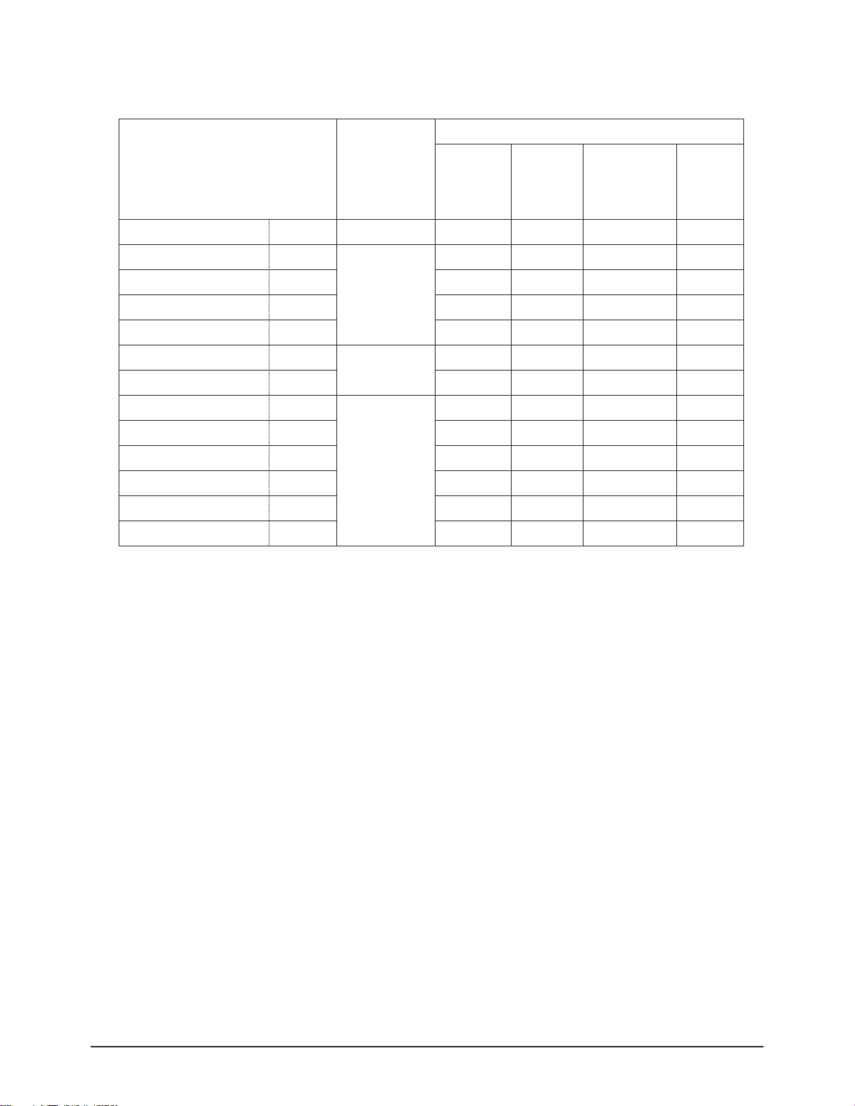
01.Picture Improve => 03.Contrast & Brightness Enhancement
03.Cont/Bri Enhancement
01.Contrast
02.Brightness
03.RGB/YUV Contrast
04.RGB/YUV Brightness
05.FLI-Contrast
06.FLI-Brightness
07.R Contrast
08.G Contrast
09.B Contrast
10.R Brightness
11.G Brightness
12.B Brightness
TV
40
27
28
67
128
128
32
32
32
0
0
0
Mode-1
40
27
28
67
128
128
32
32
32
0
0
0
Mode-2
x
x
x
x
x
x
32
32
32
0
0
0
Mode-3
x
x
x
x
x
x
32
32
32
0
0
0
Mode-4
x
x
x
x
x
x
32
32
32
0
0
0
Initial Values of Input Modes
PC(D4 ONLY) DVI
Relevant IC
VPC3230
FLI2310
ASI510
ITEM
01~04 : VPC3230
07~12 : ASI510
05~06 : FLI2310
Video
Component
Page 9
Alignment and Adjustments
Samsung Electronics 2-9
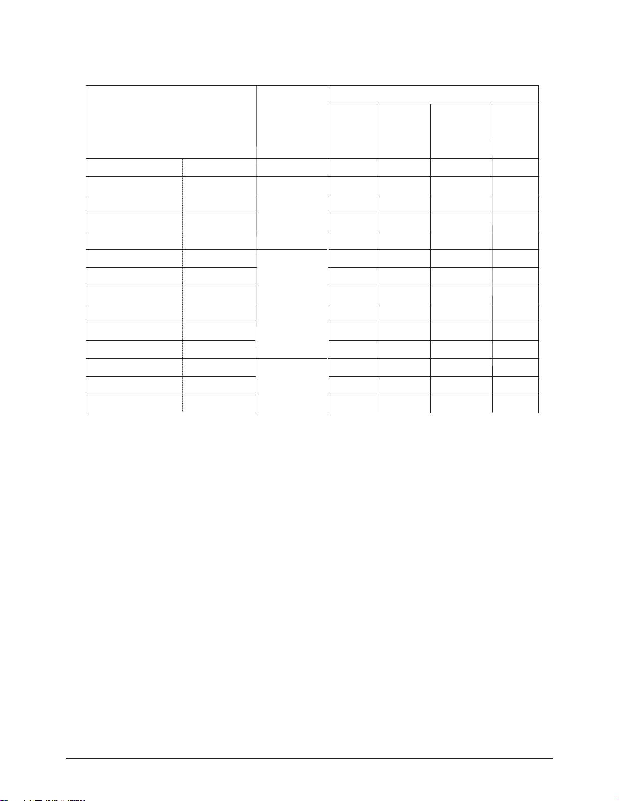
01.Picture Improve => 04.Detail Enhancement
04.Detail Enhancement
01.VAPGAIN
02.VAPINV
03.YPFT
04.YPFG
05.Peaking
06.Peaking Filter
07.Coring
08.HPLL_ERR_MIN
09.HPLL_ERR_MAX
10.V_SLICER
11.HenhGain
12.HLEGain
13.HChrEnGain
Mode-1
4
16
3
9
3
2
0
18
80
0
64
64
32
Mode-2
x
x
x
x
x
x
x
x
x
x
x
x
x
Mode-3
x
x
x
x
x
x
x
x
x
x
x
x
x
Mode-4
x
x
x
x
x
x
x
x
x
x
x
x
x
Initial Values of Input Modes
PC(D4 ONLY) DVI
Relevant IC
uPD64083
VPC3230
FLi2310
ITEM
01~04 : uPD64083
05~10 : VPC3230
11~13 : FLI2310
Video
Component
4
16
3
9
3
2
0
18
80
0
64
64
32
TV
Page 10
Alignment and Adjustments
2-10 Samsung Electronics
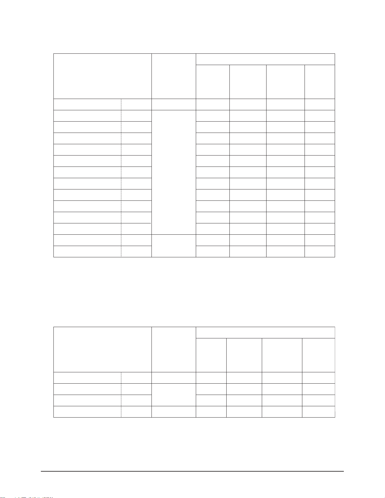
01.Picture Improve => 05.Y/C Delay Setting according to the System and Input Modes
05.Y/C Delay
01. PAL-B/G
02. PAL-D/K/L
03. PAL-I
04. SECAM-B/G
05. SECAM-D/K/L
06. NTSC
07. PAL-AV
08. SECAM-AV
09. NTSC-AV
10. RGB/YUV-Y
11. RGB/YUV-UV
12. FLI-Y
13. FLI-C
TV
255
254
254
251
250
254
254
252
254
90
90
5
11
Mode-1
255
254
254
251
250
254
254
252
254
0
0
5
11
Mode-2
x
x
x
x
x
x
x
x
x
x
x
x
x
Mode-3
x
x
x
x
x
x
x
x
x
x
x
x
x
Mode-4
x
x
x
x
x
x
x
x
x
x
x
x
x
Initial Values of Input Modes
PC(D4 ONLY) DVI
Relevant IC
VPC3230
ITEM
01.Picture Improve => 06.Motion Enhancing Adjustment
06.Motion
01.HPLL Speed-1
02.Auto Lock
03.V-motion Tresh
TV
2
0
42
Mode-1
2
0
42
Mode-2
x
x
x
Mode-3
x
x
x
Mode-4
x
x
x
Initial Values of Input Modes
PC(D4 ONLY) DVI
Relevant IC
VPC3230
FLi2310
ITEM
01~11 : VPC3230
12~13 : FLI2310
01 ~ 02 : VPC3230
03 : FLI2310
Video
Component
Video
Component
FLI2310
Page 11
Alignment and Adjustments
Samsung Electronics 2-11
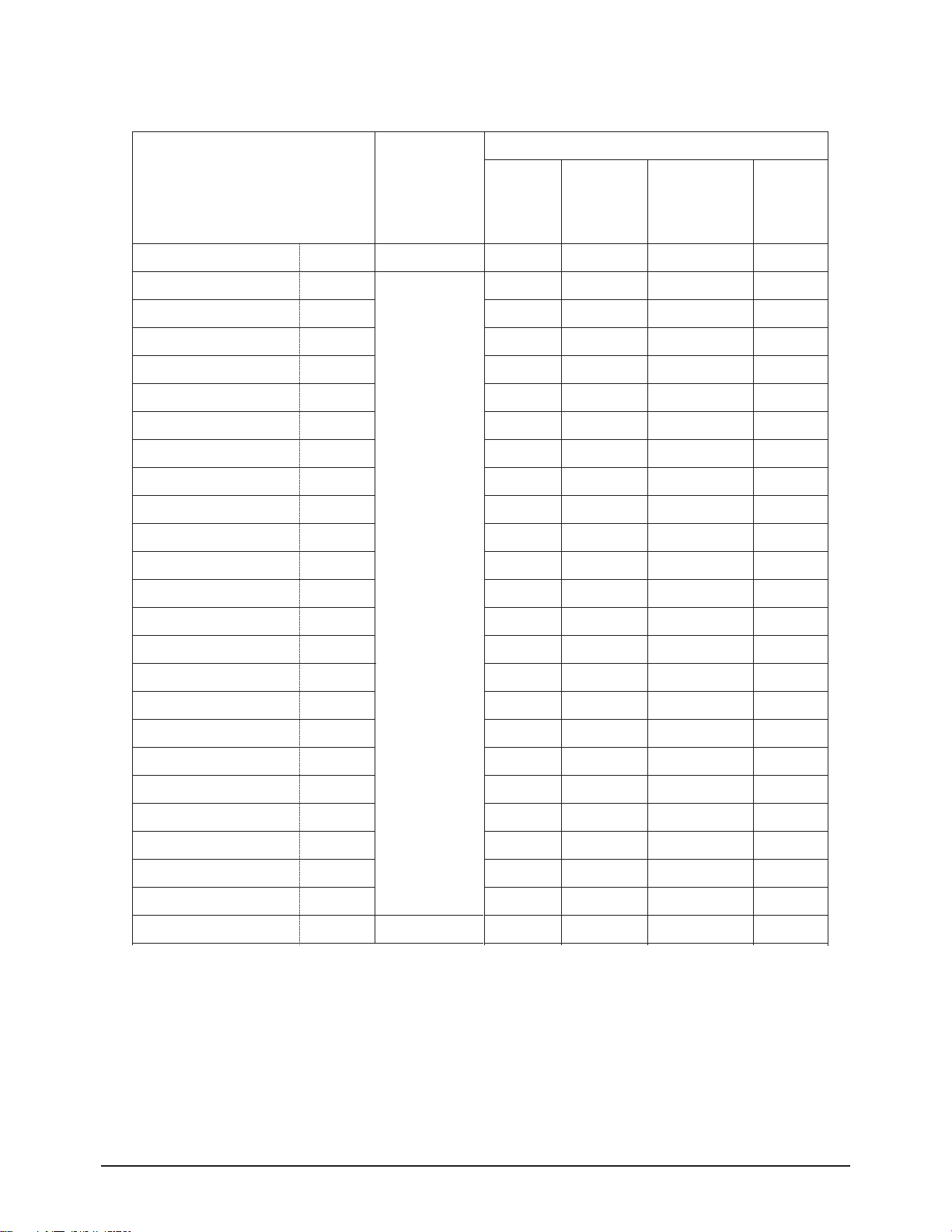
01.Picture Improve => 07.DNIe Registers
07.DNIe
01.SUB BRIGHT
02.SUB CONT
03.SCALE MAX
04.SCALE MIN
05.TH HPF
06.TH EDGE
07.NR SEL
08.CE UPPER
09.CE CUTOFF
10. CE GAIN
11. DCE GAIN
12. SKIN ON
13. CTI GAIN
14. DE NOISE GAIN
15. TH CORING
16. PATT SEL
17.DE NR
18. NOISE TH2
19. H CONT
20. V CONT
21. BLACK GAIN
22. WHITE GAIN
23. WTE GAIN
24. CTE GAIN
TV
54
37
48
16
0
4
2
240
32
64
75
0
0
8
3
0
1
100
63
11
2
31
44
176
Mode-1
54
37
48
16
0
4
2
220
32
64
75
0
0
8
3
0
1
100
63
32
11
31
44
176
Mode-2
54
37
48
16
0
4
2
200
32
80
75
0
0
8
3
0
1
100
63
63
6
31
44
176
Mode-3
54
37
48
16
0
4
2
240
32
64
75
0
0
8
3
0
1
100
63
63
2
31
44
176
Mode-4
54
37
48
16
0
4
2
240
32
64
75
0
0
8
3
0
1
100
63
63
2
31
44
176
Initial Values of Input Modes
PC(D4 ONLY) DVI
Relevant IC
DNIe
ITEM
01~24 : DNIe
Video
Component
Page 12
Alignment and Adjustments
2-12 Samsung Electronics
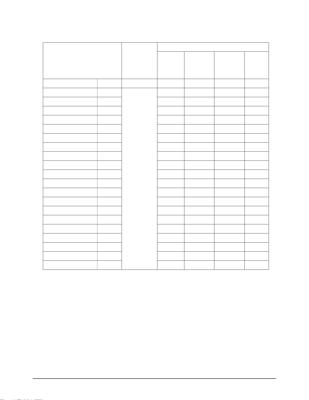
01.Picture Improve => 08.Logic Registers
08.Logic
01.R DRIVE
02.G DRIVE
03.B DRIVE
04.R CUTOFF
05.G CUTOFF
06.B CUTOFF
07.GAMMA
08.GTS SET
09.ERD MODE
10.RANDOM NOISE
11.DIFF FILTER
12.APC
13.APC SET
14.APC VALUE
15.ACTIVE VPOS
16.ACTIVE HPOS
17.VSYNC POS
18.HSYNC POS
19.VSYNC WIDTH
20.HSYNC WIDTH
TV
140
130
120
128
128
128
1
1
2
0
1
1
0
127
12
19
3
32
2
12
Mode-1
140
130
120
128
128
128
1
1
2
0
1
1
0
127
12
19
3
32
2
12
Mode-2
140
130
120
128
128
128
1
1
2
0
1
1
0
127
12
19
3
32
2
12
Mode-3
140
130
120
128
128
128
1
1
2
0
1
1
0
127
12
19
3
32
2
12
Mode-4
140
130
120
128
128
128
1
1
2
0
1
1
0
127
12
19
3
32
2
12
Initial Values of Input Modes
PC(D4 ONLY)
DVI
Relevant IC
Logic
ITEM
01~20 : Logic
Video
Component
Page 13
Alignment and Adjustments
Samsung Electronics 2-13
01.Picture Improve => 09.Picture Size Registers
09.Picture Size
01. H START OFFSET
02. V START OFFSET
03. H END OFFSET
04. V END OFFSET
05.OVERSCAN B
06.OVERSCAN G
07.OVERSCAN R
TV
0
0
0
0
38
38
38
Mode-1
0
0
0
0
38
38
38
Mode-2
0
0
0
0
38
38
38
Mode-3
0
0
0
0
38
38
38
Mode-4
0
0
0
0
38
38
38
Initial Values of Input Modes
PC(D4 ONLY) DVI
Relevant IC
ASI510
ITEM
02.Initial Setting Current Input Mode
01. Initial P-Mode ▶
02. P-Mode Value ▶
03. Initial Color Tone ▶
04. Color Tone Value ▶
02.Setting the Initial Values
01.Initial P-Mode Current Input Mode
01. Dynamic
02. Standard
03. Movie
04. Custom
02.Initial Setting => 01.Initial P-Mode
02. P-Mode Value Current Input Mode
01. Dynamic ▶
02. Standard ▶
03. Movie ▶
04. Custom ▶
02.Initial Setting => 02.P-Mode Value
☞ Indicates selected input mode
☞ Reset after saving the P-Mode adjustments
☞ P-MODE the data Values
☞ Reset after saving the color tone adjustments
☞ Color tone the data Values
01~07 : ASI510
Video
Component
Available options for the PC/DVI Mode are High,Middle,
Low and Custom.
Available options for the PC/DVI Mode are High,Middle,
Low and Custom.
Page 14

Alignment and Adjustments
2-14 Samsung Electronics
02.Initial Setting Current Input Mode
01. Cool2
02. Cool1
03. Normal
04. Warm1
05. Warm2
♣ Available Settings for the PC Mode are
Custom,Color Tone 1, Color Tone 2, Color Tone 3
♣ Available options for the DVI Mode are
ColorTone1, ColorTone2, ColorTone3
02.Initial Setting => 03.Initial Color Tone
01.Dynamic Current Input Mode
01. Contrast ◀ 100 ▶
02. Brightness ◀ 45 ▶
03. Sharpness ◀ 75 ▶
04. Color ◀ 55 ▶
05. Tint ◀ 50 ▶
02.Initial Setting => 02.P-Mode Value => 01.Dynamic
02.Standard Current Input Mode
01. Contrast ◀ 80 ▶
02. Brightness ◀ 50 ▶
03. Sharpness ◀ 50 ▶
04. Color ◀ 50 ▶
05. Tint ◀ 50 ▶
02.Initial Setting => 02.P-Mode Value => 02.Standard
03.Movie Current Input Mode
01. Contrast ◀ 50 ▶
02. Brightness ◀ 55 ▶
03. Sharpness ◀ 25 ▶
04. Color ◀ 40 ▶
05. Tint ◀ 50 ▶
02.Initial Setting => 02.P-Mode Value => 03.Movie
04.Custom Current Input Mode
01. Contrast ◀ 80 ▶
02. Brightness ◀ 50 ▶
03. Sharpness ◀ 50 ▶
04. Color ◀ 50 ▶
05. Tint ◀ 50 ▶
02.Initial Setting => 02.P-Mode Value => 04.Custom
Page 15
Alignment and Adjustments
Samsung Electronics 2-15
04.Color Tone Value Current Input Mode
01. Cool2
02. Cool1
03. Normal
04. Warm1
05. Warm2
♣ Adjusting and Storing the Changes:
Change the White Balance (Color Temperature)
1. Selecting an item will display the same options as
those of White Balance.
2. Available options for the PC Mode are Custom,Color
Tone 1, Color Tone 2, Color Tone 3
3. Available options for the DVI Mode are ColorTone1,
ColorTone2, ColorTone3.
4. Data Storing is classified according to the PC Mode &
Other Modes.
02.Initial Setting => 04.Color Tone Value
03.PIP/TTX/Test Pattern
03.PIP/Test Pattern
01.PIP R CONT
02.PIP G CONT
03.PIP B CONT
04.PIP R BRIGHT
05.PIP G BRIGHT
06.PIP B BRIGHT
07.PIP FILTER LC
08.PIP FILTER ML
09.PIP FILTER MR
10.PIP FILTER UC
11. TTX CONT
12. TTX BRIGHTNESS
13.LOG PATTERN
14.LOG HIGH LEVEL
15.LOG LOW LEVEL
16.ASI COLORBAR
TV
32
32
32
0
0
0
0
0
0
0
0
0
0
255
0
1
Mode-1
32
32
32
0
0
0
0
0
0
0
0
0
0
255
0
1
Mode-2
32
32
32
0
0
0
0
0
0
0
0
0
0
255
0
1
Mode-3
32
32
32
0
0
0
0
0
0
0
0
0
0
255
0
1
Mode-4
32
32
32
0
0
0
0
0
0
0
0
0
0
255
0
1
Initial Values of Input Modes
PC(D4 ONLY) DVI
Relevant IC
ASI510
SDA6001
Logic
ASI510
ITEM
01~10 : ASI510
11~12 : SDA6001
13~16 : Logic, ASI510
Video
Component
Page 16

Alignment and Adjustments
2-16 Samsung Electronics
04.Option-1 Current Input Mode
00. D4/V4 ◀ D4 ▶
01. SCART/RCA SCART
02. CW/CS CW
03. TELE-WEB OFF
04. LANGUAGE GROUP EUROPE
05. LANGUAGE ENGLISH
06. ATM ON
07. Melody Volume 10
08. Picture Mode Dynamic
09. LNA Search OFF
10. CHILD LOCK ON
11. TOP TTX ON
12. TTX Group Osd Language
13. HIGH DEVIATION OFF
14. SD Delay 3
15. HD Delay 2
16. Video Port Graphic
17. DOC Write OFF
18. Initial Write OFF
04.Option-1
00. D4 => V4
01. SCART(Full Input) => RCA(Delete Scart)
02. CW(EUROPE) => CS(SOUTHASIA)
03. Off => On
04. Europe => Asia
05. English => 18 Languages(Europe)
06. On => Off
07. 0 ~ 20
08. Dynamic => Standard
09. Off
10. On => Off
11. On => Off
12. Osd Language => 6 Group
13. Off => On
14. O(default),1(27ms),2(54ms),3(108ms)
15. O(default),1(27ms),2(54ms),3(108ms)
16. Graphic <-> Video
17. OFF->ON
18. OFF->ON
00. D4/V4 : D4 <=> V4
-. D4 : PS42D4S MODEL (DSUB JACK it is)
-.V4 : PS42V4S MODEL (DSUB JACK nothing)
01. Scart/Rca : Scart => RCA
-.Scart : Europe & Scart area(All Input is selected)
-.RCA : Southeast Asia & RCA area(Delete Scart)
02. CW/CS : CW => CS
- CW : PAL, SECAM-B/G, D/K, I, L/L', NTSC4.43 = West Europe
- CS : PAL, SECAM-B/G, D/K, I, NTSC3.58/4.43 = Countries except West Europe.
Ex) Southeast Asia,the Middle East,Russia,China, etc.
03. Tele-Web
- Off : TeleWeb non-broadcasting Country
- On : TeleWeb broadcasting Country
04. Language Group : Europe => Asia
-. Europe : 18 languages
-. Asia : 7 languages
05. Language : Select language
- Language Group is Europe : 18 languages
(English=>Bulgarian=>Croatian=>Czechoslovak=>Netherlandish=>French=>German=>Greek=>Hungarian=>
Italian=>Poland=>Portuguese=>Rumanian=>Russian=>Spanish=>Swedish=>Turki=>Yugoslave)
- Language Group is Asia : 5 languages
(English=>French=>Chinese=>Arabic=>Persian)
06. ATM : On => Off
-. ATM available region : On
-. ATM non-available region : Off
-. ATM at the time of OFF one from Funtion item the Country is changed with the Area and the ATM is changed with auto
search.
Page 17

Alignment and Adjustments
Samsung Electronics 2-17
07. Melody Volume
-.Able to adjust from 0 to 20.
08. Picture Mode : Dynamic <=>Standard
09. LNA Search
-. On : Using LNA, Auto Search
-. Off : Not in use LNA, Auto Search
10. Child Lock
-. On : TV Model
-. Off : Model has deletion of Child Lock function
11. Top TTX
- On : Only Top broadcasting region set 'On'
Ex) Germany, Switzerland, etc
- Off : Country except Top broadcasting region.
12. TTX Group : TTX Language Group and National Option Code
- By language, Select at the factory option table.
- TTX language will be displayed by National Option code.
- TTX Language Group by each country : 6 Groups
West Europe => East Europe => Turkish/Greek => Cyrillic => Arabic/Hebrew => Farsi/Hebrew=>Osd Language
13. High Deviation : To prevent Sound Buzz resulting from regional conditions of the input signals.
- Set to ‘Off’ for the standardized sound input signal, in the region such as Europe.
- Set to ‘On’ for the over-modulated sound input signal, in the region such as Southeast Asia.
14. SD Delay : AV mode Delay
1.8ms delay --------- delay0
27ms delay --------- delay1
54ms delay --------- delay2
108ms delay (max) --------- delay3
15. HD Delay : DTV/PC/DVI mode Delay
16. Video Port : Setting of Aurora Input Port for VIDEO signal
-. Graphic : Input Video Signal though Graphic port of Aurora (In case of NON-PIP VIDEO)
-. Video : Input Video Signal though Graphic port of Aurora (In case of PIP VIDEO)
17. DDC Write
-.Off : Disable to write DVI DDC (DDC Write Protection)
-.On : Able to write DVI DDC
* In the initial stage of the Operational Inspection, DDC Write is enabled (DDC Write is ON).
DDC Write is disabled (DDC Write is OFF) after the Factory Reset.
* To enable DDC Write at a later time, enter Factory Mode and set this menu to ON.
18. Initial Write
Page 18

Alignment and Adjustments
2-18 Samsung Electronics
05.Option-2 Current Input Mode
00. Pixel Shift ◀ V ▶
01. Shift Test ◀ 0 ▶
02. Pixel Number ◀ 1 ▶
03. Pixel Line ◀ 1 ▶
04. Shift Time ◀ 4 ▶
05. Number Range ◀ 4 ▶
06. Line Range ◀ 4 ▶
07. Temp Protection ◀ On ▶
08. DNIe DEMO ◀ On ▶
09. PILOT HIGH ◀ 21 ▶
10. PILOT LOW ◀ 16 ▶
11. CHECKSUM ◀ 0000 ▶
05.Option-2
00. Off => V => G => V/G
01. 0: minute , 1: SEC
02. Left,right movement Pixel
03. Upper, low movement Pixel
04. Shift Test
 Loading...