

Page 1

Alignment & Adjustment
Samsung Electronics 3-1
3. Alignment & Adjustment
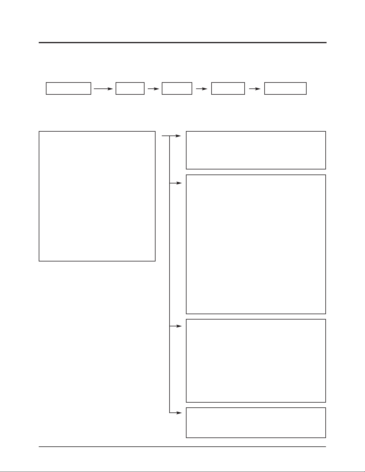
3-1 Service Instruction
* Check items listed after changing each
1. Main Board replace : ATM Channel fixing and White Balance adjustment
2. Main SMPS Board replace: Vs, Va Voltage check and adjust
5. DC-DC SMPS Board replace : Output voltage check and adjust
6. Logic Board replace : Not adjustment
7 : Y-Main Board replace : Not adjustment
8 : X-Main Board replace : Not adjustment
9 : Buffer Board replace : Not adjustment
Page 2
Alignment & Adjustment
3-2 Samsung Electronics
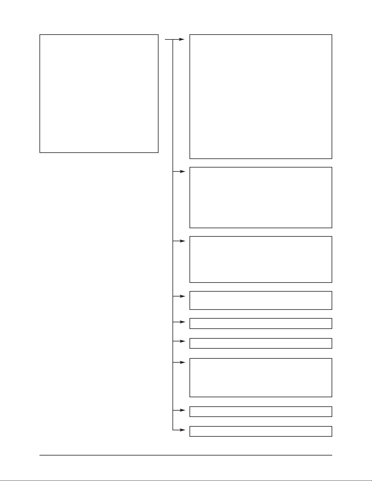
3-2 Factory Mode Adjustments
3-2-1 Entering Factory Mode
To enter 'Service Mode' Press the remote -control keys in this sequence :
- If you do not have Factory remote - control
3-2-2 Factory Mode Tree
- If you have Factory remote - control
[INFO] →→[FACTORY]
Power OFF MENU MUTE Power OnINFO
1. Calibration
2. Option Byte
3. W/B
4. VCTi
5. YC Delay
6. FLI5961
7. Adjust
8. Test Pattern
9. Password
10. Check Sum
11. Spread Spectrum
12. HDCP
13. Download
14. Reset
T-TWS42PEUS-XXXX
P-TRNPEU-XXXX
Firmware Version
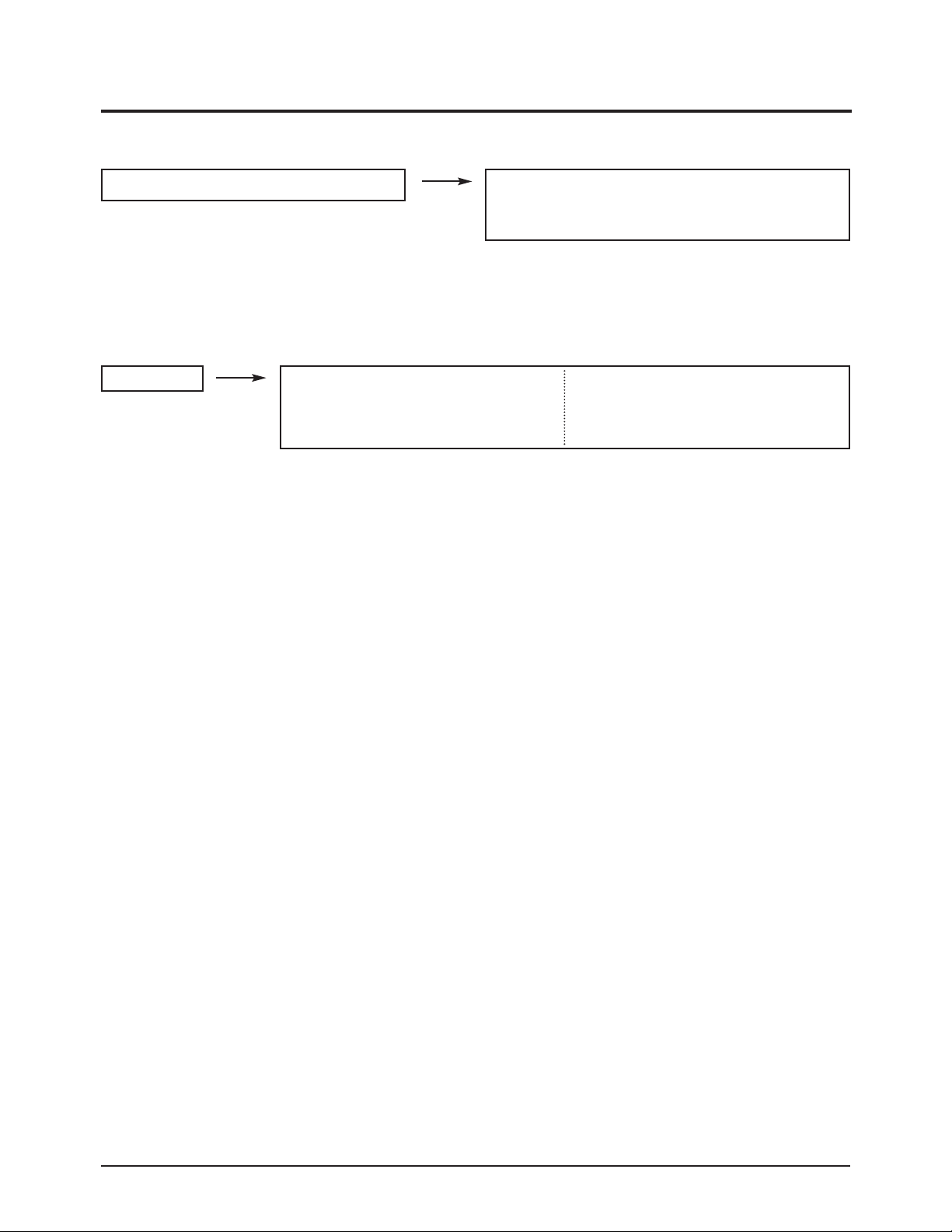
1. Calibration : W/B Calibration
AV Calibration
DTV Calibration
PC Calibration
2. Option byte : Setting option
Panel option : 42" PDP
Gamma
:
off/on
Auto Power : on/off
Video Mute : 5
Language : English
Hotel Mode : off/on
LNA Plus : off/on
V-chip : off
Auto FM : off/on
High Deviation : off/on
TTX List : Flop/List
TTX Top : off/on
TTX Group :
User OSD/West Europe/East Europe/
Russian/Greek
· Turkey/Arabic/
Farisian/Arab.Habrew/Off
DVI : on/off
- - - - :
3. W/B : Adjustment White Balance
( Range 0~255 )
Sub Bright : 128
R off set : 128
G off set : 128
B off set : 128
Sub contrast : 128
R gain : 128
G gain : 128
B gain : 128
4.
VCTi
:
VCTi IC Correct register
VCTi Page 1
VCTi Page 2
Page 3
Alignment & Adjustment
Samsung Electronics 3-3
1. Calibration
2. Option Byte
3. W/B
4. VCTi
5. YC Delay
6. FLI5961
7. Adjust
8. Test Pattern
9. Chip Debugger
10. Check Sum
11. Spread Spectrum
12. HDCP
13. Reset
T-TRNPEU-0000 month day year time
P-TRNPEU-0000
Panel On Time(Hour) 0000
5. YC Delay
RF PAL-B/G : 5
RF PAL-D/K : 6
RF PAL-I : 5
RF PAL-L/L' : 7
RF SECAM-B/G : 2
RF SECAM-D/K : 0
RF SECAM-I : 2
RF SECAM-L/L' : 6
RF NTSC 3.58 : 5
RF NTSC 4.43 : 5
AV PA L : 5
AV SECAM : 7
AV NTSC 3.58 : 5
AV NTSC 4.43 : 5
AV PAL 60 : 5
6. FLI5961 : Scaler IC Correct register
Component Calibration
: Result DTV Calibration
PC Calibration : Result PC Calibration
ACC/ACM
TNR
Picture Enhance
User W/B
7. Adjust
User Control lnitial
LNA PLUS
Hotel Option
Pixel Shift
11. Spread Spectrum
Spread Spectrum
: on/off
Spread Spectrum Range
: 2
Step : 63
8. Test Pattern : VCTi IC'S own test patterns.
(Total 7 patterns)
10. Check Sum : 0000
12. HDCP : 0000
13. Download : Off/On
9. Password : Use IC Register Correction.
Page 4
Alignment & Adjustment
3-4 Samsung Electronics
3-3 White Balance - Calibration
3-3-2 White Balance - Adjustment
3-3-1 White Balance -Calibration
3-3-3 Conditions for Measurement
1. Calibration
DTV Calibration
PC Calibration
(Calibration Condition refer to next page)
3. W/B
(low light) (hight light)
1. On the basis of toshiba ABL pattern : High Light level (57 IRE)
- INPUT SIGNAL GENERATOR : MSPG-925LTH
* Mode NO 1 : 744X484@60 Hz
NO 6 : 1280X720@60 Hz (Component 720P)
NO 21 : 1024X768@60 Hz
*
Pattern
NO 15 : Color bar
NO 16 : Toshiba ABL Pattern
NO 17 : 16 gray
2. Optical measuring device : CA210 (FL)
Please use the MSPG-925 LTH generator for model LNR2355W,LNR2755W,LNR3255W.
(W/B adjustment Condition refer next page)
Sub Bright Sub Contrast
R offset R gain
G offset G gain
B offset B gain
Page 5
Alignment & Adjustment
Samsung Electronics 3-5
2. Adjust the white balance of AV, Component and DVI Modes.
a) Set the input to the mode in which the adjustment will be made (AV Component DVI).
* Input signal - VIDEO Mode : Model #1 (744X484 Mode), Pattern #16
- Component, DVI Mode : Model #6 (1280X720 Mode), Pattern #16
b) Enter factory W/B.
c) Adjust the low light.
- Adjust sub - Brightness to set the 'Y' value.
- Adjust red offset ('x') and blue offset ('y') to the color coordinates. ( x : 280, y : 285, Y : 1.1fL)
* Do not adjust green offset data.
3-3-4 Method of Adjustment
1. Adjust the basic level of Component and PC input signals.
a) Set the input to the mode in which the adjustment will be made (Component PC ).
* Input signal - Component Mode : Model #6 (1280X720 Mode), Pattern #15 (picture 4-1)
- PC Mode : Model #21 (1024X768 Mode), Pattern #17 (Picture 4-2)
b) Enter factory Calibration (DTV, PC Mode Only).
* DTV Calibration Source change for PC PC Calibration
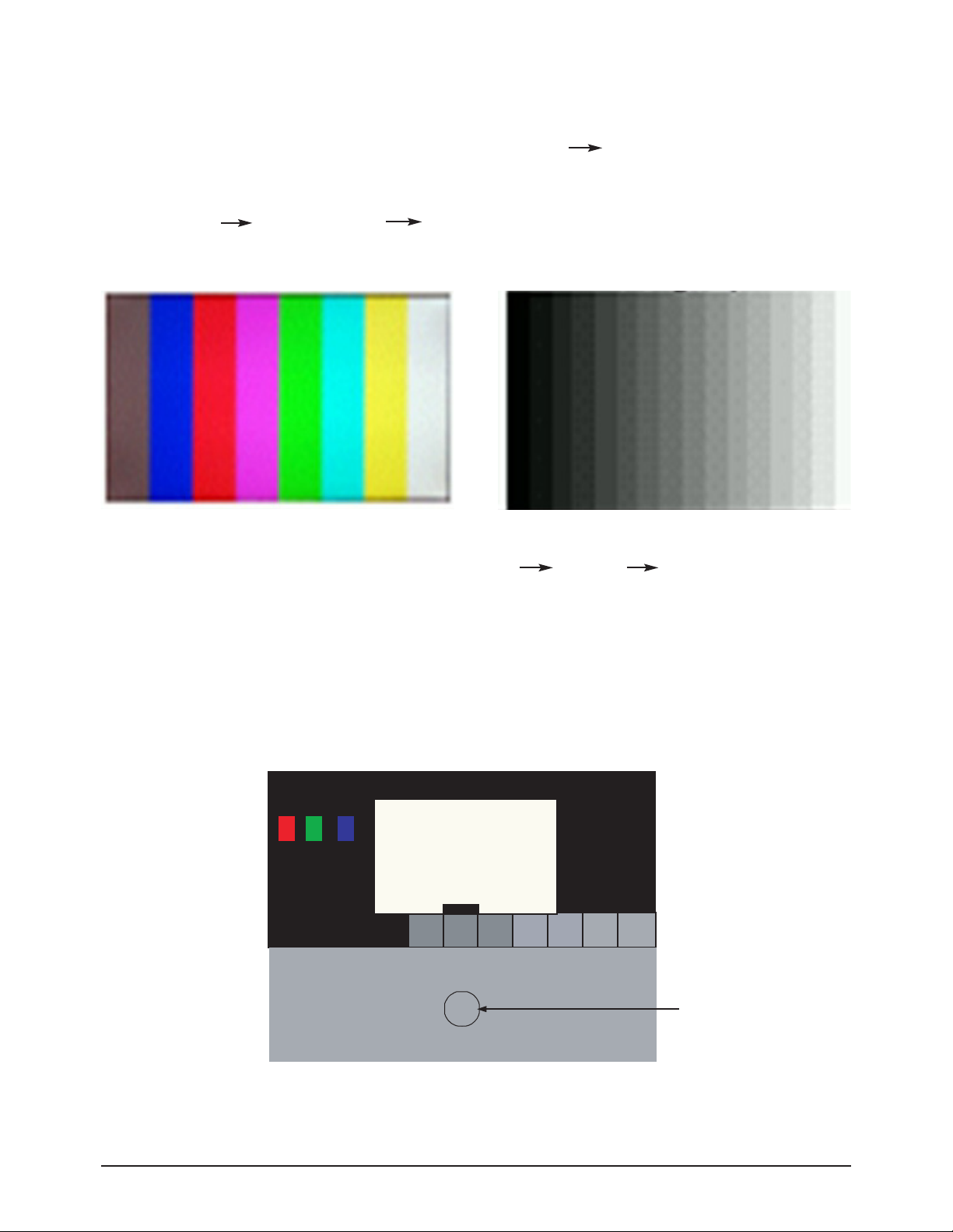
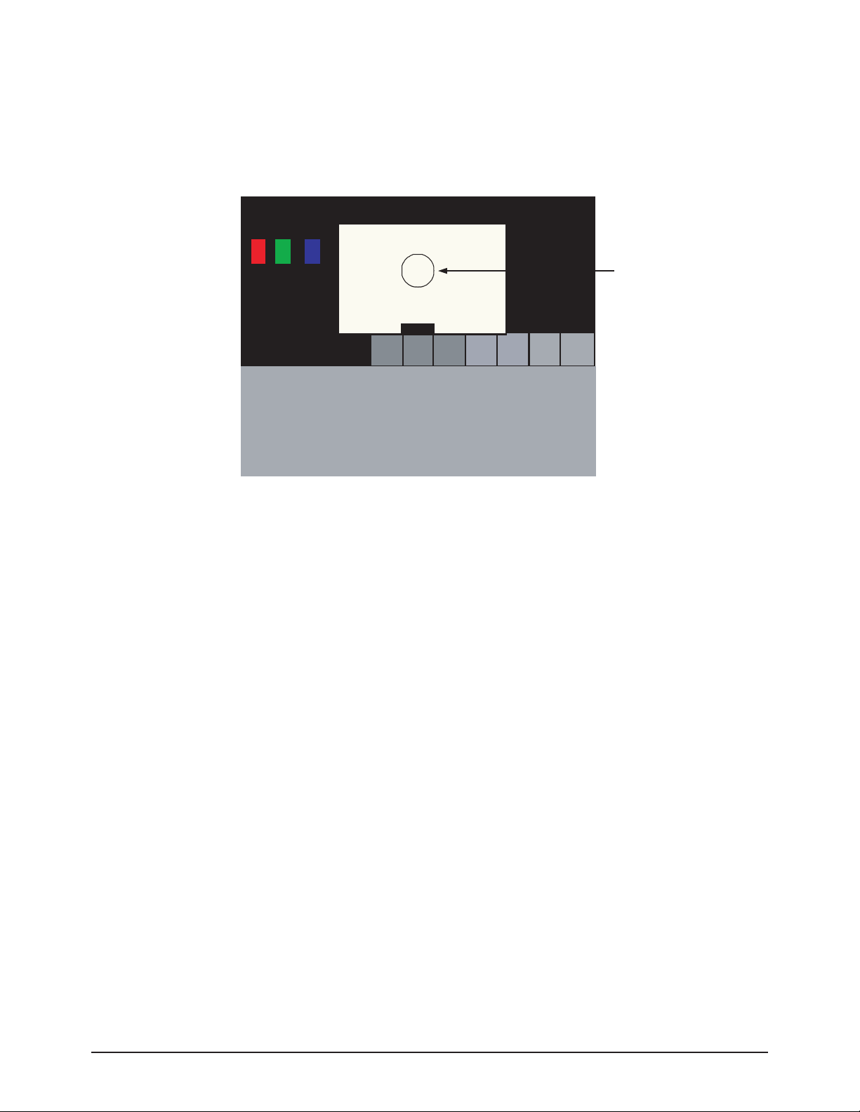
Picture 4-1 Color bar
Picture 4-2 16gray
Picture 4-3 Toshiba ABL Pattern
Low light
Measurement point
Page 6
Alignment & Adjustment
3-6 Samsung Electronics
Picture 4-4 Toshiba ABL Pattern
High light
Measurement point
d) Adjust the high light. (Refer to table 1, 2 in adjustment position by mode)
- Adjust red gain ('x') and blue gain ('y') to the color coordinates. ( x : 265, y : 265 )
* Do not adjust the green gain and sub-contrast (Y) data.
Page 7
Alignment & Adjustment
Samsung Electronics 3-7
3-4 Micom Update
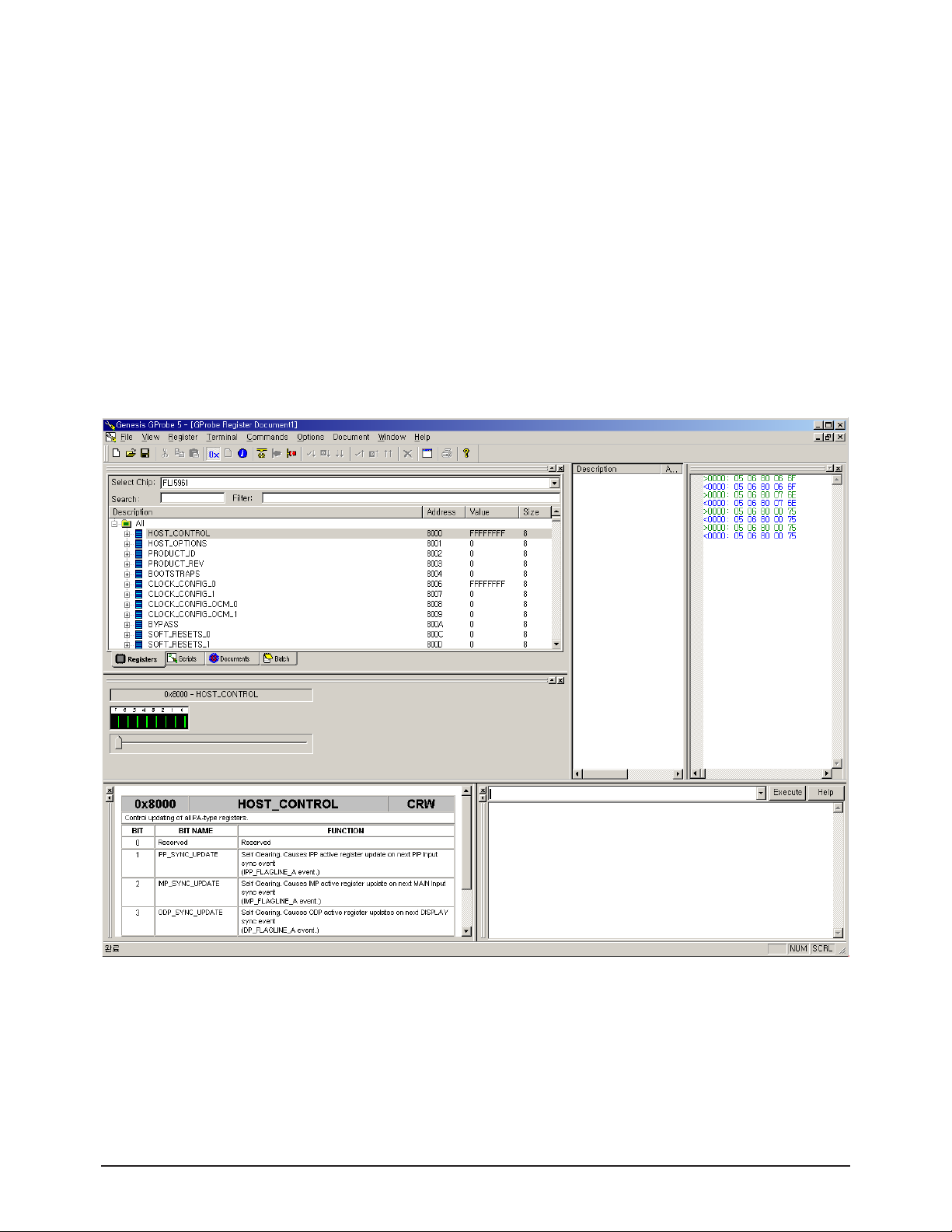
3-4-1 Installing G-Probe
1. Uncompress GProbe5.1.0.18.zip.
2. Run GProbe5.1.0.18.exe.
3. The files are created in the C:₩Program Files₩Genesis Microchip₩GProbe 5 folder.
4. Copy the ispoak_spi.hex file to the C:₩Program Files₩Genesis Microchip₩GProbe 5 folder.
5. Uncompress FLI5961-AC_GProbe_S0006-CSC-33B.zip.
6. Three files are extracted (FLI5961.Chip.GProbe, FLI5961.chm, outputlog.txt).
7. Copy all 3 files to the C:₩Program Files₩Genesis Microchip₩GProbe 5₩ChipDB folder.
8. Run GProbe.exe in the C:₩Program Files₩Genesis Microchip₩GProbe 5 folder. The G-Probe program is created.
<The screen that appears when G-Probe is successfully installed>
Page 8
Alignment & Adjustment
3-8 Samsung Electronics
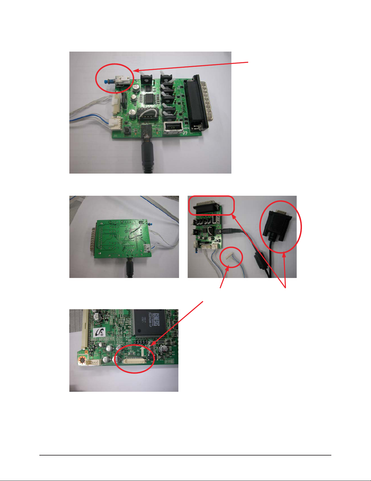
3-4-2 Connecting to the MAIN PCB
Switch off
<Bottom Side>
Connect to the PC
Connect to the MAIN PCB.
<Micom Download Jig Top Side: Note the direction of the switch>
Page 9

Alignment & Adjustment
Samsung Electronics 3-9
3-4-3 Update Procedures
1. Open twister.txt in the C:₩Program Files₩Genesis Microchip₩GProbe 5 folder.
2. The following result will appear.
//
// Batch file to program a sPI serial flash using ISP.
// Moving the stack to high memory area is now taken care of in IROM
// through the "Reset 0" command. Assumes the ISP driver is in the same
// directory as this file. Change ISP driver path in "fastFlashWrite"
// command, if different from current directory.
//
debugon
SetBuffer 0x2000 0x800
delay 200
Reset 0
delay 500
// SPI flash driver
RAMWrite ispoak_spi.hex
Run 0x500
delay 100
// Optional - Get Flash ID. The second parameter is a don't care
//FLASHCRC 0xff0000 0x20000
// Command delay for flash erase
SetDelay 1000 9000
FlashErase
// Command delay for flash write. This is for each flash write packet (upto 4 k Bytes)
SetDelay 1000 3000
// Change this line to point to a file in a different location, if needed
//fastFlashWrite C:₩Proj₩OAK₩APP-59xx₩debug₩obj₩59xx_proj.hex
fastFlashWrite C:₩C:₩Program Files₩Genesis Microchip₩GProbe 5₩T_TWSPEU.hex
// Optional - Get CRC of 128 kByte flash. For other sizes, change second parameter
// accordingly
//FLASHCRC 0x80000 0x20000
// to reset the monitor after programming the flash using DDC2BI ONLY:
// Un-comment the following three lines (PLEASE - FOR DDC2BI PORT SELECTED ONLY)
//0x8000=1
//0x8003=0
//0x8027=1
Page 10
Alignment & Adjustment
3-10 Samsung Electronics
The Micom program is to be copied to the folder marked in red and the name of the program is to be the same as the file name
marked in blue.
(If the Micom program is not in the folder marked in red, change the path to the folder which includes the Micom program and
then save the file.)
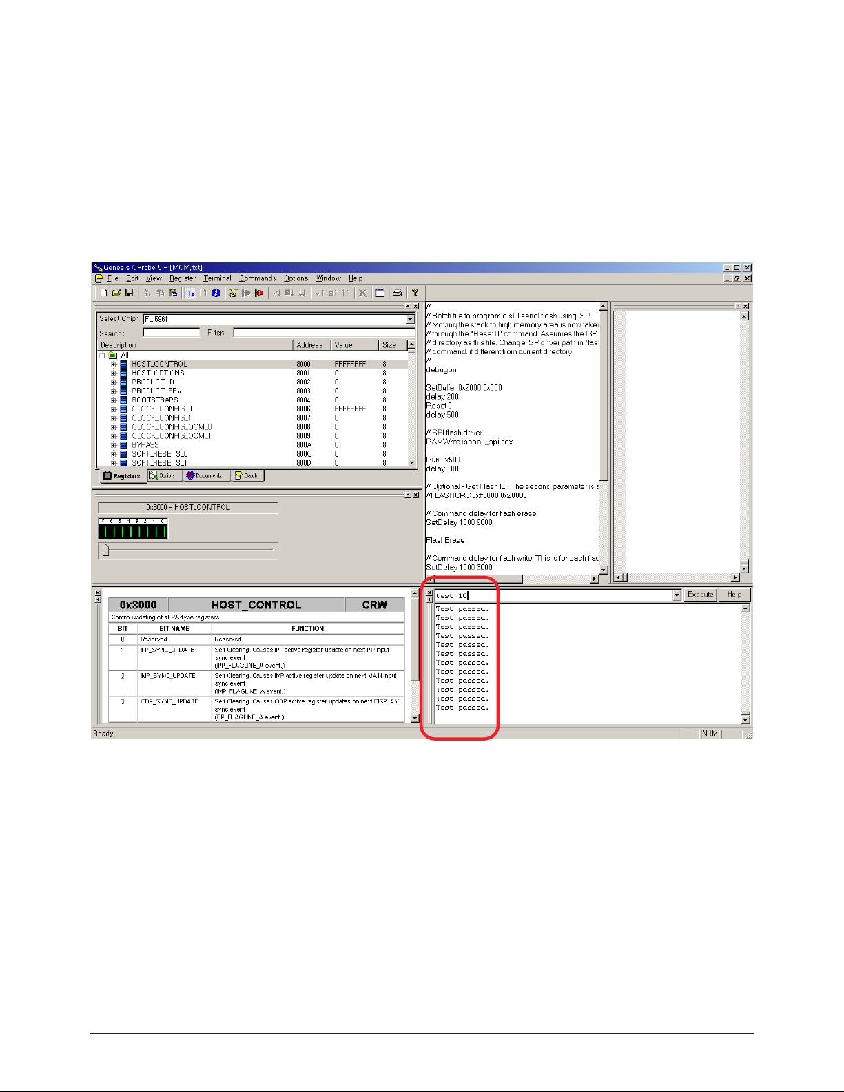
3. When completing all the procedures above, connect the Jig and the PCB, and run the G-Probe program.
After that Enter 'test 10' as shown in the following figure and press Enter or click the Execute button.
If the result appears as shown in the following figure, it is properly connected.
Page 11
Alignment & Adjustment
Samsung Electronics 3-11
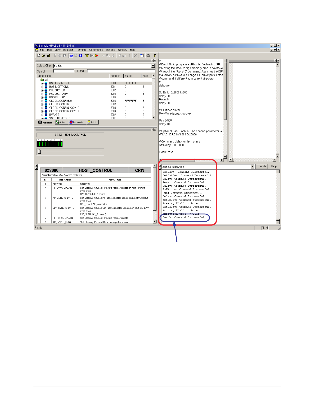
4. Enter "batch twister.txt" as show in the following figure and press Enter or click the Execute button to update Micom.
If the MICOM update is successfully completed, the above
message appears.
Page 12
Alignment & Adjustment
3-12 Samsung Electronics
3-5 Replacements & Calibration
3-5-1 Voltage Adjustment
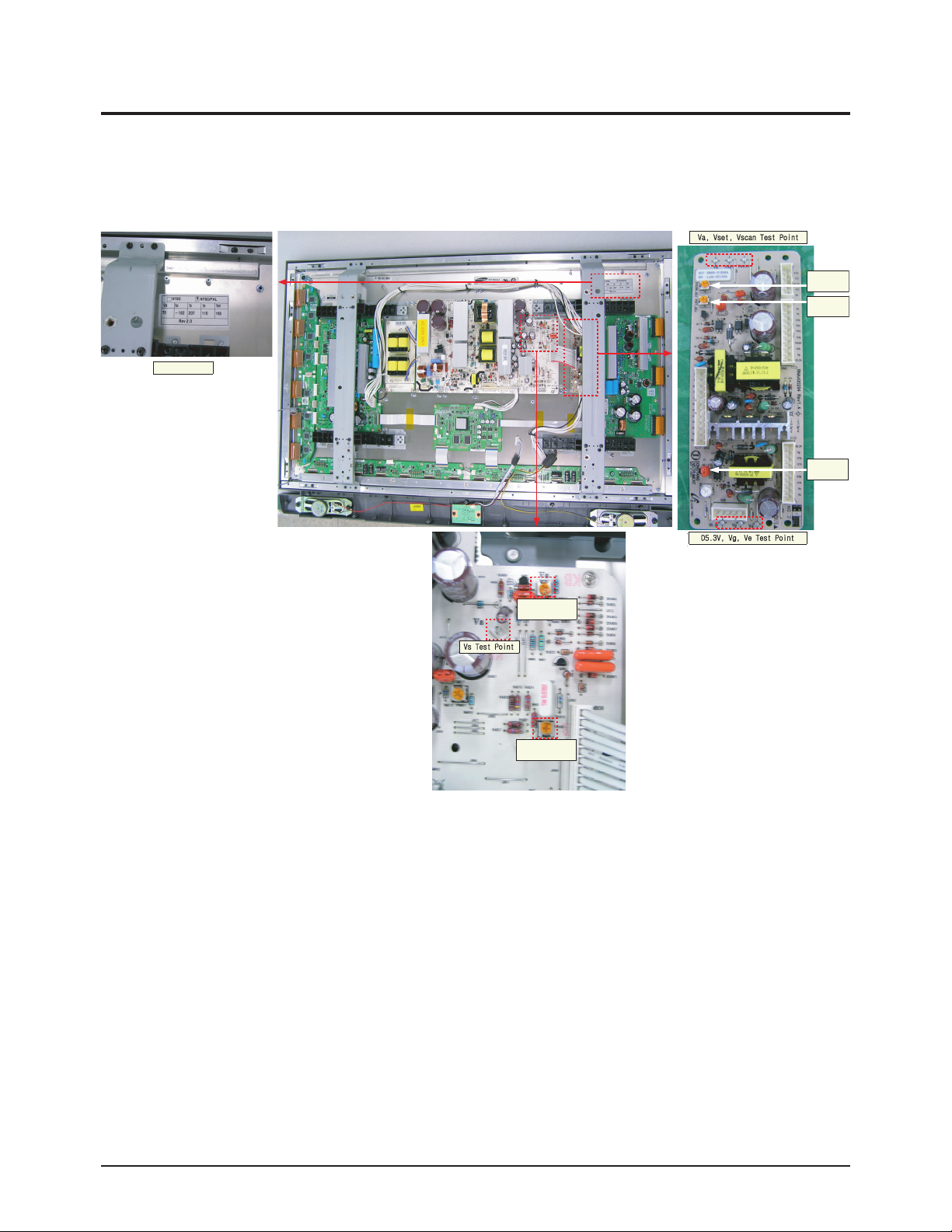
※ When the SMPS is replaced, the Va, Vs voltages must be checked and adjusted to the proper levels indicated on the panel
sticker.
adjustment
adjustment
Voltage Label
adjustment
Vscan
Vset
Ve
VRU801 VS
adjustment
VRA801 Va
adjustment
 Loading...