

Samsung AV-R610, AH68-01853S User Manual

SAMSUNG ELECTRONICS CANADA, INC.
HEADQUARTERS
55 Standish Court Mississauga, Ontario L5R 4B2 Canada
TEL: 1-905-542-3535
www.samsung.ca
SERVICE DIVISION
55 Standish Court Mississauga, Ontario L5R 4B2 Canada
1-800-SAMSUNG (1-800-726-7864)
AH68-01853S
Digital Surround
AV Receiver System
HT-AS610
Instruction Manual
(AV -R610)
Safety Warnings
CAUTION
RISK OF ELECTRIC SHOCK.
DO NOT OPEN
CAUTION:
TO REDUCE THE RISK OF ELECTRIC
SHOCK, DO NOT REMOVE REAR COVER.
NO USER SERVICEABLE PARTS INSIDE.
REFER SERVICING TO QUALIFIED
SERVICE PERSONNEL.
This symbol indicates that dangerous voltage which can cause electric shock is present inside
this unit.
This symbol alerts you to important operating and maintenance instructions accompanying
the unit.
Note to CATV system installer :
This reminder is provided to call the CATV system
installer’s attention to Section 820~40 of the NEC
which provides guidelines for proper grounding and,
in particular, specifies that the cable ground shall be
connected to the grounding system of the building,
as close to the point of cable entry as practical
WARNING : To reduce the risk of fire or electric shock, do not expose this appliance to rain or moisture.
CAUTION : TO PREVENT ELECTRIC SHOCK, MATCH WIDE BLADE OF PLUG TO WIDE SLOT, FULLY
INSERT.
2
Precautions
VOLUME
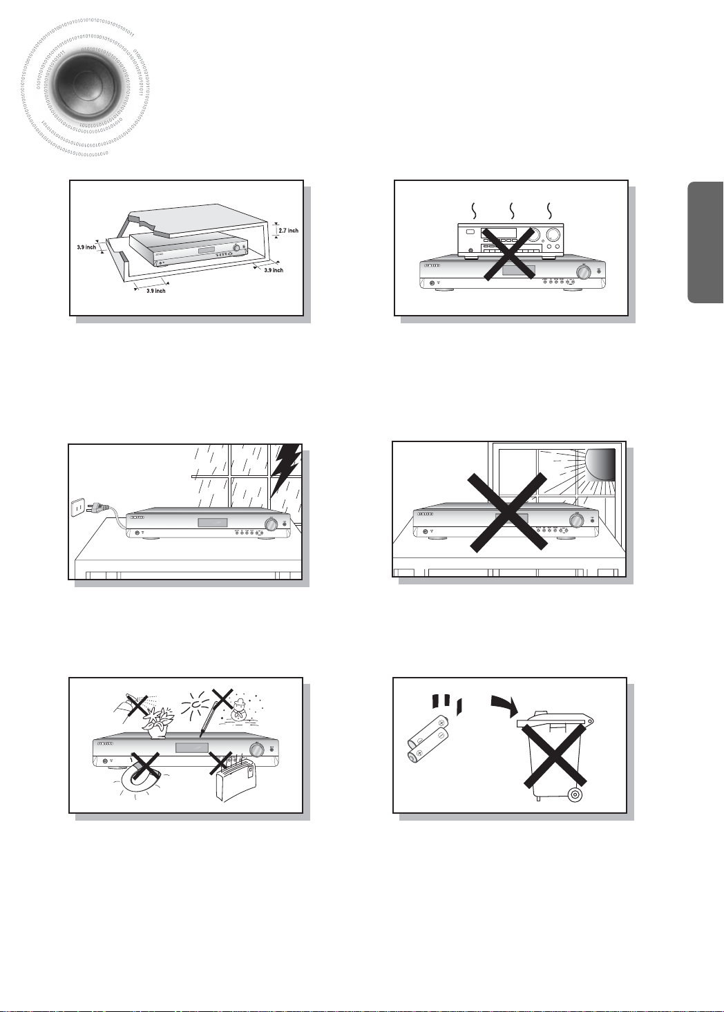
Ensure that the AC power supply in your house complies with the identification sticker located on the back of your player. Install
your player horizontally, on a suitable base (furniture), with enough space around it for ventilation (3~4inches). Make sure the
ventilation slots are not covered. Do not stack anything on top of the player. Do not place the player on amplifiers or other
equipment which may become hot. Before moving the player, ensure the disc tray is empty. This player is designed for
continuous use. Switching off the DVD player to the stand-by mode does not disconnect the electrical supply. In order to
disconnect the player completely from the power supply, remove the main plug from the wall outlet, especially when left unused
for a long period of time.
PREP ARATION
During thunderstorms, disconnect AC main plug from
the wall outlet.
Voltage peaks due to lightning could damage the unit.
Protect the player from moisture(i.e. vases) , and excess
heat(e.g.fireplace) or equipment creating strong magnetic or
electric fields (i.e.speakers...). Disconnect the power cable from
the AC supply if the player malfunctions. Your player is not
intended for industrial use.
Use of this product is for personal use only.
Condensation may occur if your player or disc have been
stored in cold temperatures.
If transporting the player during the winter, wait approximately
2 hours until the unit has reached room temperature before using.
Do not expose the unit to direct sunlight or other heat
sources.
This could lead to overheating and malfunction of the
unit.
The battery used with this product contain chemicals
that are harmful to the environment.
Do not dispose of batteries in the general household
trash.
3

Features
Digital AV Receiver
This product is a pure digital AV receiver that performs digital signal processing to minimize
signal distortion and loss.
Dolby Pro Logic II
Dolby Pro Logic II is a new form of multi-channel audio signal
decoding technology that improves upon existing Dolby Pro Logic.
DTS (Digital Theater Systems)
DTS play backs 5.1 channel sound with less compression than Dolby
Digital for richer sound.
SFE(Sound Field Effect) Using 24bit Audio DSP
Provides more realistic surround sound with normal stereo audio sources.
4

Contents
PREPARATION
Safety Warnings..............................................................................................................2
Precautions......................................................................................................................3
Features ..........................................................................................................................4
Description ......................................................................................................................6
CONNECTIONS
Connecting the Speakers................................................................................................10
Connecting External Components ..................................................................................12
Connecting the FM and AM Antennas.............................................................................15
OPERATION
Before Using the AV Receiver.........................................................................................16
Selecting Digital/Analog Input .........................................................................................18
Setting the Speaker Mode...............................................................................................20
Setting the Speaker Listening Distance .........................................................................22
Setting Digital Input .........................................................................................................24
Setting DRC (Dynamic Range Compression) .................................................................25
Test Tone ........................................................................................................................26
Setting Speaker Level .....................................................................................................28
Dolby Pro Logic ll Mode..................................................................................................30
Dolby Pro Logic ll Effect .................................................................................................32
SFE Mode........................................................................................................................34
Stereo Mode....................................................................................................................36
PREP ARATION
RADIO OPERATION
Listening to Radio ...........................................................................................................38
Presetting Radio Stations ...............................................................................................39
MISCELLANEOUS
Convenient Functions......................................................................................................40
Operating TV with Remote Control..................................................................................42
Operating your VCR (DVD) with Remote Control............................................................44
Before Calling for Service................................................................................................46
Specifications ..................................................................................................................48
WARRANTY....................................................................................................................49
5
Description
,
,
[
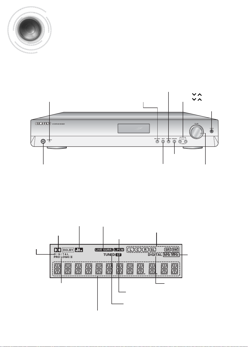
Front Panel
POWER STANDBY Indicator
POWER button
[
Display
]
]
FUNCTION button
SELECT ( ) button
INPUT MODE button
SETUP button
TUNING ( ) button
HEADPHONE Jack
SURROUND button
VOLUME CONTROL
DOLBY DIGITAL
6
INDICATOR
DOLBY
INDICATOR
INDICATOR
DOLBY PRO
LOGIC II
INDICATOR
DTS
LIVE SURROUND
FRONT DISPLAY
INDICATOR
L.PCM
INDICATOR
SPEAKER INDICATOR
RADIO FREQUENCY
INDICATOR
DIGITAL INDICATOR
RADIO STEREO INDICATOR
RADIO BROADCASTING
RECEIVING INDICATOR
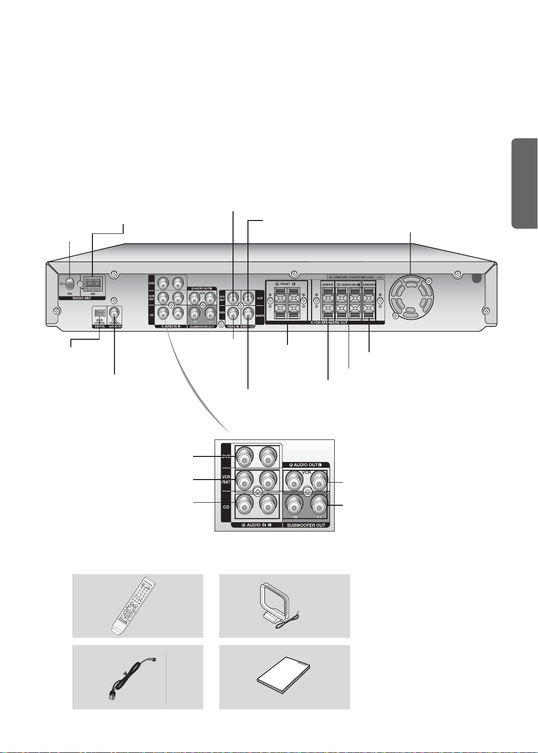
[
Rear Panel
AM ANTENNA
FM ANTENNA
JACK
JACK
]
VCR/SAT VIDEO INPUT
JACK
VCR VIDEO OUTPUT
JACK
COOLING FAN
PREP ARATION
DVD OPTICAL DIGITAL
AUDIO INPUT JACK
CD COAXIAL DIGITAL
AUDIO INPUT JACK
DVD AUDIO INPUT JACKS
VCR/SAT AUDIO INPUT JACKS
CD AUDIO INPUT JACKS
Accessories
√√
DVD VIDEO INPUT
œœ
Remote Control
JACK
MONITOR VIDEO
OUTPUT JACK
FRONT SPEAKER
TERMINALS
SUBWOOFER SPEAKER TERMINALS
SURROUND SPEAKER TERMINALS
CENTER SPEAKER TERMINALS
VCR AUDIO OUTPUT JACKS
SUBWOOFER OUTPUT JACKS 1, 2
AM Antenna
FM Antenna User’s Manual
7
Description
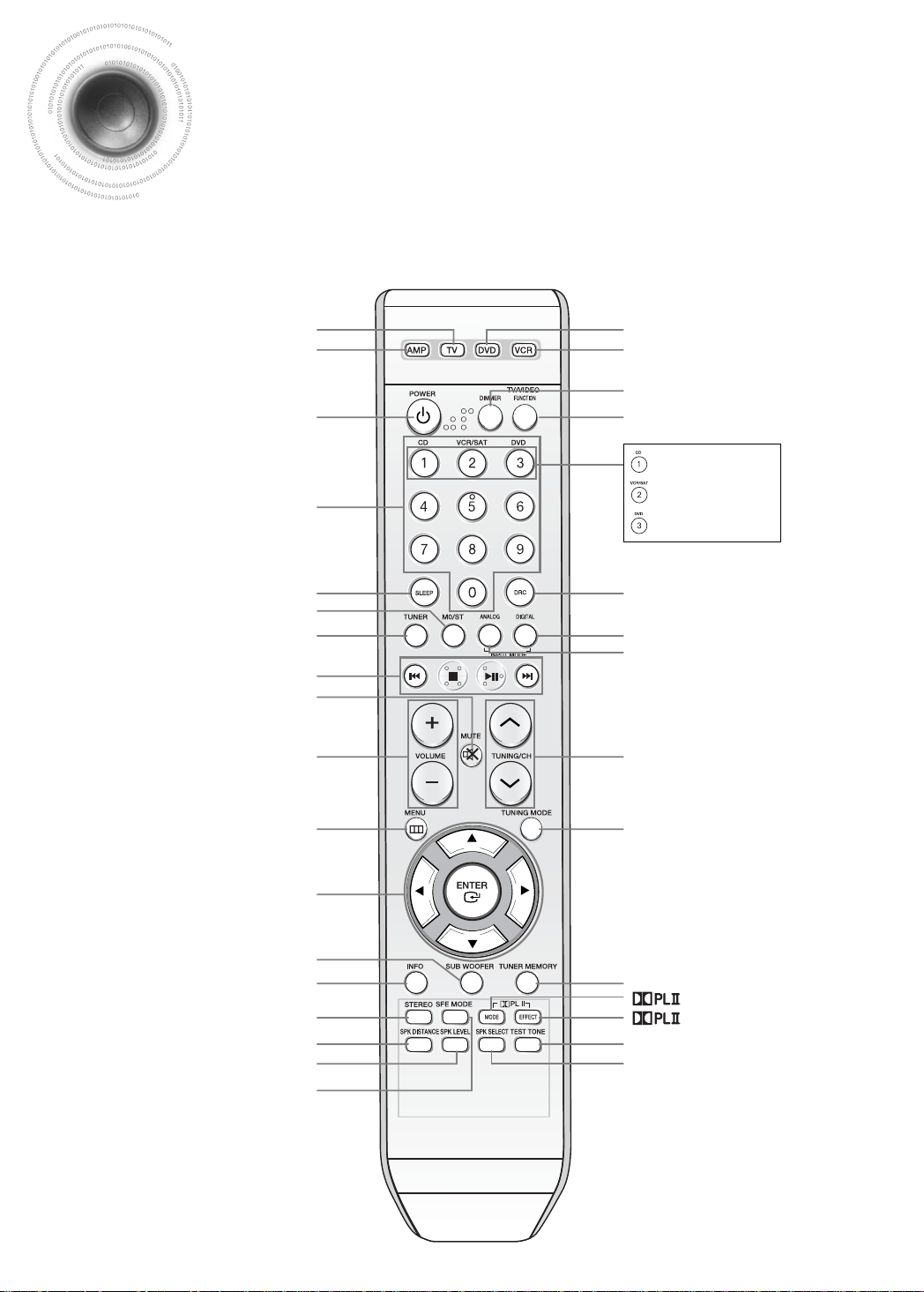
[
Remote Control
AMP button
POWER button
NUMBER(0~9) buttons
SLEEP button
MO/ST button
TUNER button
EXTERNAL DEVICE PLAYBACK button
MUTE button
VOLUME CONTROL button
]
TV button
DVD button
VCR button
DIMMER button
,
TV VIDEO
DRC button
INPUT MODE DIGITAL button
INPUT MODE ANALOG button
TUNER/CHANNEL button
FUNCTION button
CD button
VCR/SAT button
DVD button
8
MENU button
CUSOR/ENTER button
SUBWOOFER button
INFO button
STEREO button
SPK DISTANCE button
SPK LEVEL button
SFE MODE button
TUNING MODE button
TUNER MEMORY button
MODE button
EFFECT button
TEST TONE button
SPK SELECT button
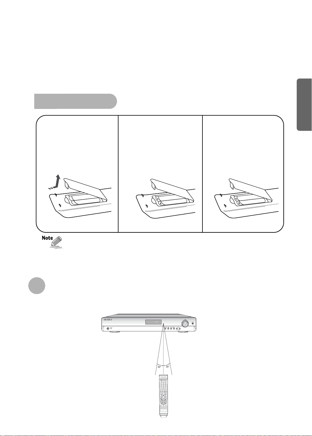
Insert Remote Batteries
PREP ARATION
Remove the battery
1
cover in the direction
of the arrow.
Follow these precautions to avoid leaking or cracking batteries:
Place batteries in the remote control so they match the polarity:(+) to (+)and (–)to (–).
•
Use the correct type of batteries.Batteries that look similar may differ in voltage.
•
Always replace both batteries at the same time.
•
Do not expose batteries to heat or flame.
•
Insert two 1.5V AAA
2
batteries, paying
attention to the correct
polarities (+ and –).
Replace the battery
3
cover.
Range of Operation of the Remote Control
The remote control can be used up to approximately 23 feet/7 meters in a straight line. It can also be operated
at a horizontal angle of up to 30° from the remote control sensor.
9
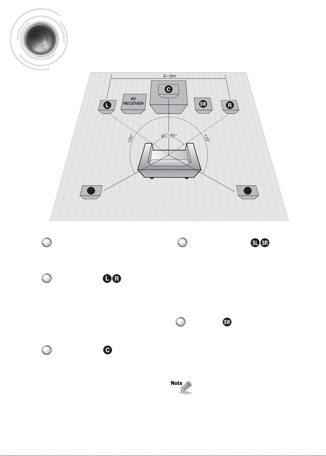
Connecting the Speakers
SL SR
Before moving or installing the product, be sure to turn off the power and disconnect the power cord.
Position of A V Receiver
•
Place AV Receiver on a dedicated stand or rack.
Front Speakers
•
Place these speakers in front of your listening
position, facing inwards (about 45°) toward you.
•
Place the speakers so that their tweeters will be at
the same height as your ear.
•
Align the front face of the front speakers with the
front face of the center speaker or place them
slightly in front of the center speakers.
Surround Speakers
•
Place these speakers behind your listening position.
•
If there isn't enough room, place these speakers so they
face each other.
•
Place them about 60 to 90cm (2 to 3feet) above your ear,
facing slightly downward.
❈ Unlike the front and center speakers, the surround
speakers are used to handle mainly sound effects and
sound will not come from them all the time.
Subwoofer
•
The position of the subwoofer is not so critical.
Place it anywhere you like.
Center Speaker
•
It is best to install it at the same height as the front
speakers.
•
You can also install it directly over or under the TV.
•
When you attach the speakers to a wall, make sure to
fasten them tightly so they do not fall off.
10
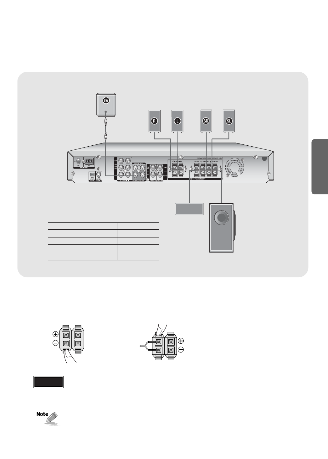
ACTIVE SUBWOOFER
(not supplied)
•
If more bass is desired, you can
connect an additional active
subwoofer (not supplied) to the
Subwoofer 1or 2 port. Since the
signal on the Subwoofer 1and 2 ports
is not stereo, you will hear the same
mono bass sound regardless of the
port you connect to.
SYSTEM MODEL NAME : HT-AS610
MAIN UNIT AV-R610
FRONT SPEAKER PS-AF610
CENTER SPEAKER PS-AC610
SURROUND SPEAKER PS-AR610
PASSIVE SUB WOOFER PS-AW610
FRONT (R)
PS-AF610
FRONT (L)
PS-AF610
CENTER
PS-AC610
SURROUND (R)
PS-AR610
PASSIVE
SUBWOOFER
PS-AW610
SURROUND (L)
PS-AR610
CONNECTIONS
MAIN UNIT
AV-R610
√ Connecting Speaker Wire
Press the tab of the
1
speaker connector.
Caution
•
Keep the subwoofer speaker out of reach of children so as to prevent children from inserting their hands or alien
substances into the duct (hole) of the subwoofer speaker.
•
Do not hang on the wall through the duct (hole).
•
Never touch speaker terminals while the power is on.
Doing so could result in electric shock.
•
Make sure the polarities (+ and -) are correct.
2
Insert the black wire into the black(-)
terminal and the gray wire into the
red(+) terminal.
11
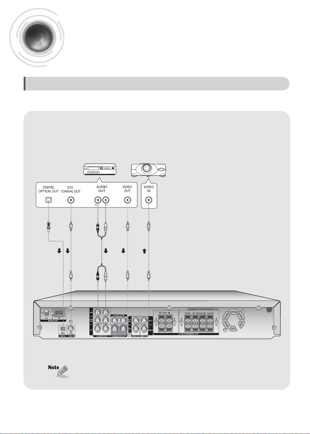
Connecting External Components
Connecting Video Component
Before moving or installing the product, be sure to turn off the power and disconnect the power cord.
DVD Player
Video Projector
12
•
Disconnect the power plug from the outlet if you will not use this unit for a long period of time.
•
In a DVD/CD player, you can select one digital audio input from OPTICAL and COAXIAL.
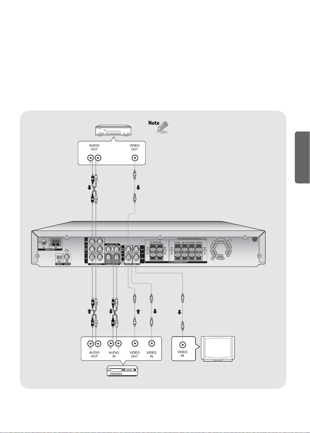
(Settop Box)
SAT
•
If using VCR, connect Analog Audio Out to VCR/SAT
Audio In on this unit. If using STB, connect Digital
Out to the SAT Optical connector on this unit.
•
The Analog Audio and Video In jacks of the main unit
are used for SAT and VCR. You cannot connect both
devices at the same time.
•
If there is a Digital Out for the satellite/cable STB, it
can be connected to the SAT Optical connector on
the rear panel to provide multi-channel surround. If
there is no Digital Out connector on the STB, connect
the Analog Audio Out connector to the VCR/SAT
Audio In on the unit.
•
If the external component has only one Audio Output
jack, connect it to either the right or left Audio Input
jack of the main unit.
•
Connect the audio cable's red plug to the red jack
and white cable to the white jack.
CONNECTIONS
VCR
TV
13
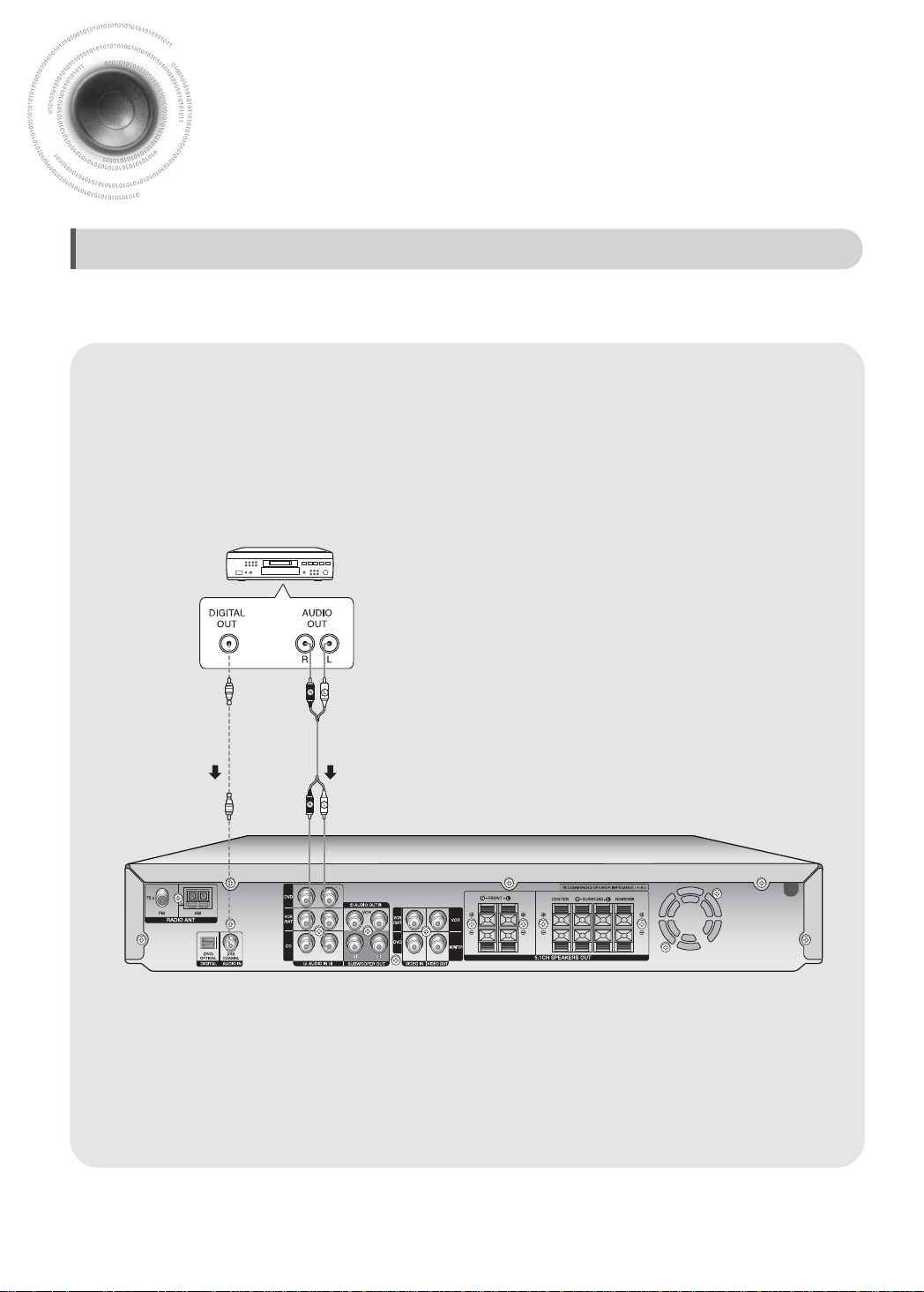
Connecting External Components
Connecting Audio Component
Before moving or installing the product, be sure to turn off the power and disconnect the power cord.
CD Player
14
 Loading...