

Page 1
5. Troubleshooting
5-1 Items to be checked first
1 ) Is the voltage of the power corre c t ?
The input voltage shall be the rating Voltage ±10% range.
The airconditioner may not operate properly if the voltage is out of this range.
2 ) Is the link cable linking the indoor unit and the outdoor unit linked pro p e r l y ?
The indoor unit and the outdoor unit shall be linked by 4 cables.
Check the terminals if the indoor unit and outdoor unit are properly linked by the same number
of cables.
Otherwise the airconditioner may not operate pro p e r l y.
3 ) When a problem occurs due to the contents illustrated in the table below it is a symptom not re l a t-
ed to the malfunction of the airc o n d i t i o n e r.
NO Operation of air conditioner
1 The COOL operation indication LED (Green) blinks for 3minutes
when a power plug of the outdoor unit is plugged in for the
first time.
2 In a COOL operation mode, the compressor does not operate
at a room temperature lower than the setting temperature.
In a HEAT operation mode, the compressor does not operate at
a room temperature higher than the setting temperature.
3 Fan speed setting is not allowed in AUTO or DRY mode.
4 Compressor stops operation intermittently in DRY mode.
5 Compressor of the outdoor unit is operating although the
indoor unit is turned off in a HEAT mode.
6 Timer LED only of the indoor unit lights up and the
air conditioner does not operate.
7 The compressor and indoor fan stop intermittently in HEAT
mode.
8 Indoor fan and outdoor fan stop operation intermittently in
a HEAT mode.
9 The compressor stops intermittently in a COOL mode or DRY
mode, and fan speed of the indoor unit decreases.
Explanation
It indicates power is on. The LED stops blinking if the operation ON/OFF
button on the remote control unit is pushed.
The speed of the indoor fan is set to LL in DRY mode.
Fan speed is 5 steps is selected automatically in AUTO mode.
Compressor operation is controlled automatically in DRY mode depending on the room temperature and humidity.
When the unit is turned off while de-ice is activated, the compressor
continues operation for up to 12 minutes (maximum) until the deice is
completed.
Timer is being activated and the unit is in ready mode.
The unit operates normally if the timer operation is cancelled.
The compressor and indoor fan stop intermittently if room temperature
exceeds a setting temperature in order to protect the compressor from
being overheated in a HEAT mode.
The compressor operates in a reverse cycle to remove exterior ice in a
HEAT mode, and indoor fan and outdoor fan do not operate intermittently for within 20% of the total heater operation
The compressor stops intermittently or the fan speed of the indoor unit
decreases to prevent indoor heat exchanger from being frozen.
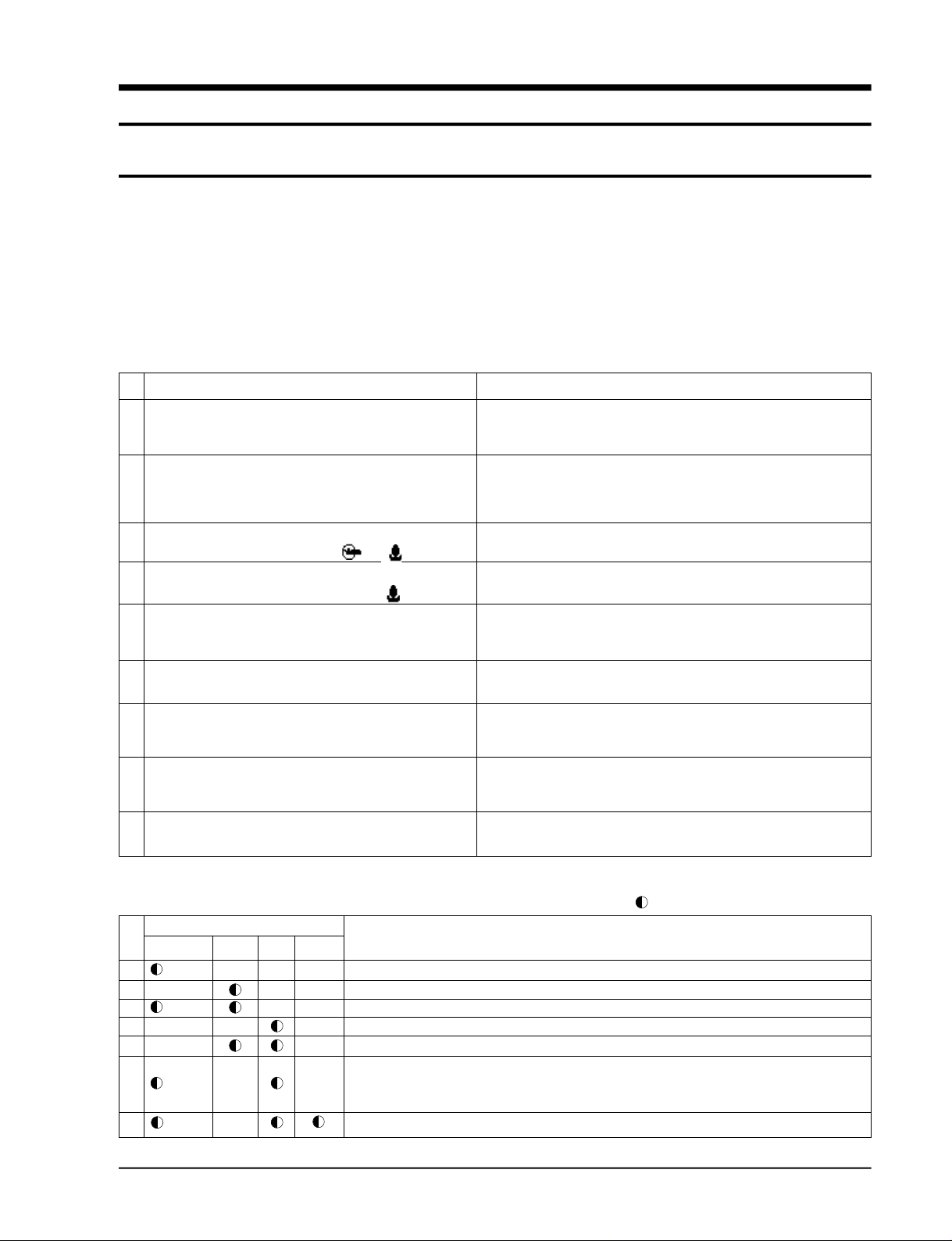
4 ) Indoor unit observes operation condition of the air conditioner, and displays self diagnosis details
on the display panel.
NO
Operating Timer Fan Turbo
1
(GREEN)
2
3
4
5
6
7
X
(GREEN)
X
X
(GREEN)
(GREEN)
Display
X
X
X
X
Samsung Electronics
Self Diagnosis
X
X
Restore from power failure (input initial power)
X
X
Indoor unit Room sensor Error (open or short)
X
X
Indoor unit heat exchanger temperature sensor Error (open or short)
X
Indoor fan malfunctioning (for speed is below 450rpm)
X
In case that the communication between the indoor unit and outdoor unit is not made for 60 seconds
Outdoor sensor Error (open or short)
X
- Outdoor sensor
- Pipe sensor A, B
The malfunction ot 4way valve in heat mode operation.
: Lamp blinking X : Lamp OFF
5-1
Page 2
5-2 Checking and Testing Operations (Outdoor Unit)
To complete the installation, perform the following checks and tests to ensure that
the air conditioner is operating corre c t l y.
1. Review all the following elements in the installation:
• Installation site stre n g t h
• Piping connection tightness to detect any gas leakages
• Connection wiring
• Heat-resistant insulation of the piping
• Drainage
• Earthing wire connection
• Correct operations (follow the steps below)
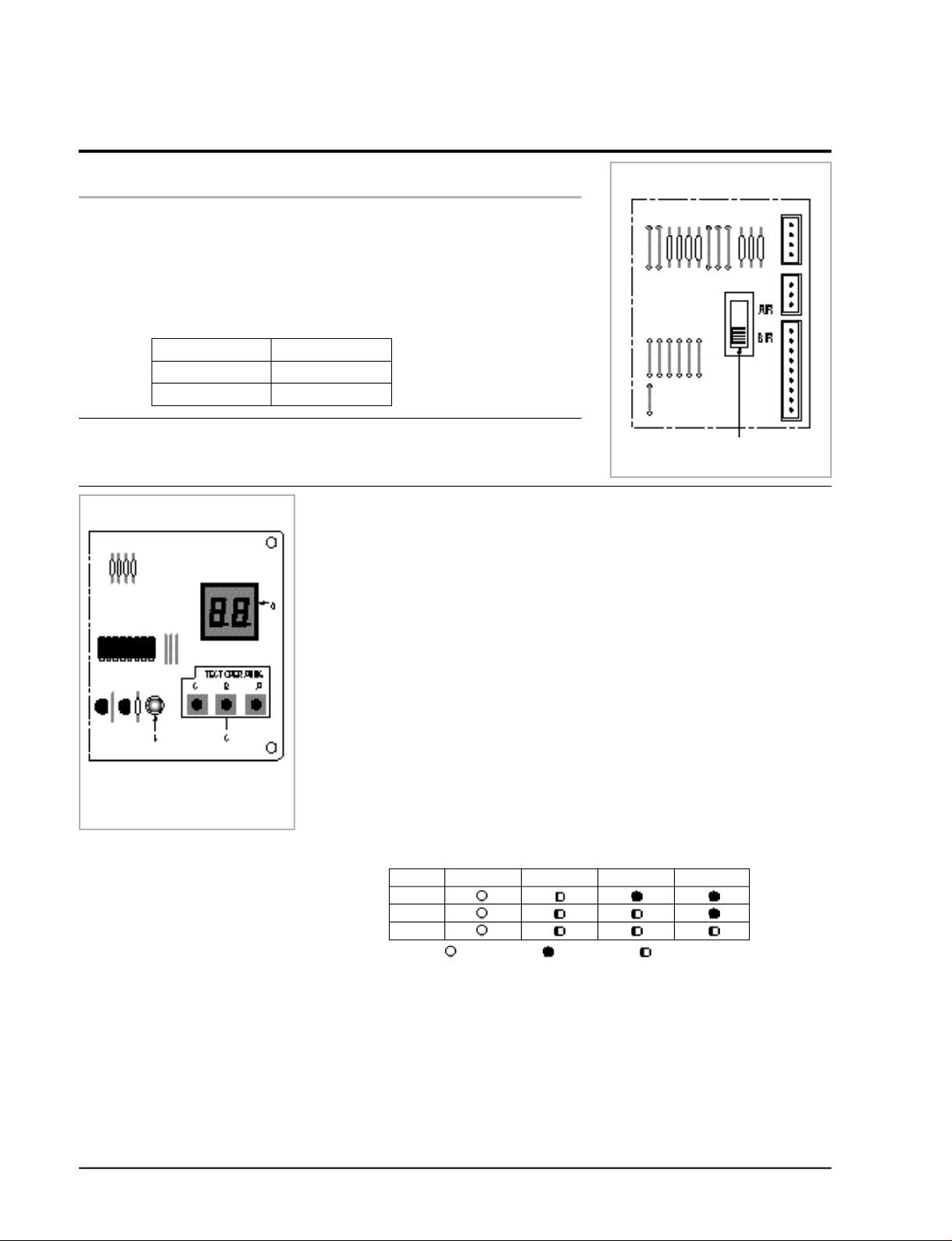
• Room select switch in the indoor unit
ROOM NO
A unit
B unit
2. Apply the power to the outdoor unit.
- Check the fuse (250V~, 5A) : The fuse is open when the power line
OUTDOOR UNIT
Room select switch
A/R
B/R
(L, N) is short.
3. Check the connection of PCB communication of outdoor unit.
(Check whether the red LED of outdoor unit PCB is flickering.)
• The communication lamp is flickering after the display of each unit on
the outdoor PCB display part. (every one second).
LED is not flikering, if the connection is bad or the room select switch is
located in the wrong position.
- LED lamp (red) flickering after display of A (1 sec)
- LED lamp (red) flickering after display of b (1 sec)
- LED lamp (red) flickering after display of C (1 sec)
Note : PCB switch “C” is used for triple split multi air conditioner.
R e s u l t : If all of three units display lamps are flickering, the connection
w i res and the room option connections are good.
INDOOR UNIT
Room select switch(A, B unit)
A : PCB display
B : Red LED
C : PCB switch
If the lamp is not flickering, check as follows:
A. Check the display part of indoor unit of each unit (A,B) after outdoor
unit PCB switch S/W- A is on.
Check the status of each unit indoor room select switch.
(Adjust the select switch suitable to the unit A, B.)
- A unit : OPERATION LED on, TIMER LED flickering
- B unit : O P E R ATION LED on, TIMER and FAN LED flickering
- C unit : O P E R ATION LED on, TIMER and FAN, TURBO LED
B. Check the communication connection of outdoor unit PCB
(Check whether the red LED of outdoor unit PCB is flickering).
The communication lamp is flickering after the display of each unit on the
outdoor unit PCB. (every one second)
- LED lamp (red) is flickering after display of A (1 sec)
- LED lamp (red) is flickering after display of b (1 sec)
- LED lamp (red) is flickering after display of C (1 sec)
Result: If all of three units display lamps are flickering, the connection
flickering (In case of triple split multi air conditioner)
UNIT
OPERATION TIMER FAN TURBO
A
B
C
Lamp ON
w i res and the room option connections are good.
Lamp OFF Lamp Flasher
5-2
Samsung Electronics
Page 3

Troubleshooting
DISPLAY EXPLANATION
Outdoor sensor error (Short/Open)
Outdoor A cond pipe sensor error (Short/Open)
Outdoor B cond pipe sensor error (Short/Open)
Outdoor C cond pipe sensor error (Short/Open)
A unit test operation error
B unit test operation error
C unit test operation error
A unit test communication error
B unit test communication error
C unit test communication error
A,B,C unit all communication error
A room test operation OK
B room test operation OK
REMARK
Be sure to check after applying the power
to the outdoor unit.
Display when the test operation finishes.
• When the pipe temperature difference of
indoor unit (pipe temperature 4 minutes before
- Actual pipe temperature) is less than 5˚C.
Be sure to check during the test operation.
Display of power application.
Display 4 minutes after the COMP is on.
C room test operation OK
Communication unit number display : A unit
Communication unit number display : B unit
Communication unit number display : C unit
(In case of triple split multi air conditioner)
•Normal operation
Unit A,B and C are changed every one second.
The communication lamp is flickering after
display of each unit.
(possibility to check the communication status)
•During the test operation the unit under test
is on and off every 0.25s.
Samsung Electronics
5-3
Page 4
Troubleshooting
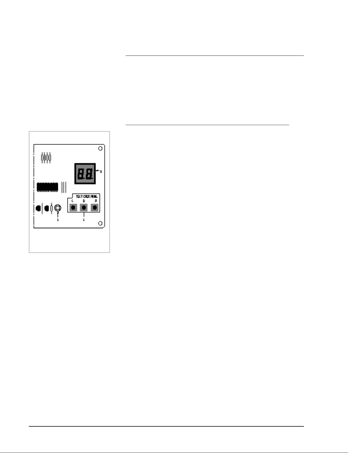
4. Check the test operation status by pressing the PCB switch
S / W- A and S/W-B of outdoor unit.
• Check the operation status by pushing the switch one at time.
• Perform the test operation only for the unit selected last.
• Check the pipe pre s s u re and the other operation status
during the test operation.
• Check items when the error occurs during the test operation
(each unit)
- Check there is enough re f r i g e r a n t .
- Check pipe connections.
OUTDOOR UNIT
a : PCB display
b : Red LED
c : PCB switch
EEXXAAMMPPLLE
E
• In case of unit A test, push once the PCB switch S/W- A ( s a m e
for unit B).
- In such a case, the indoor unit of unit A is operated
automatically by the outdoor unit.
- In case the unit A test stops, push once more the switch
S / W- A .
< Operation >
1. Once the test is started, the COMP is on and Good (displayed
Gd) or Error (displayed Er) is displayed after 4 minutes .
: Taking diff e rence between the present temperature of
indoor heat exchanger and the temperature 4 minutes later,
if the temperature diff e rence is over 5°C, the connection is
good or if the temperature diff e rence is below 5°C, the
connection is bad.
2. If the result of the test operation is good operation, is
possible for 30 minutes max.
If there is an erro r, the outdoor unit shall be stopped
i m m e d i a t e l y.
If an error occurs, push switch S/W- A or S/W-B once to
resume from the error status. Restart is then possible.
3. Once the test operation is completed, push switch S/W- A o r
S / W-B to finish the test.
4. Once the test is completed, operate the indoor unit normally.
5. Check the operation is normal. Start up is over.
5-4
Samsung Electronics
Page 5
5-3 Fault Diagnosis by Symptom
5-3-1 When the power voltage is not available
1 ) Inspection items
(1) Is the power voltage is normal? (The rating voltage ±10% range)
(2) Is the power cord is correctly connected and is the contact good?
(3) Does the sound “ting” come out with the operation lamp (green) flickering when the
power is applied?
If it is not flickering, do inspect and repair in accordance with the following inspection
s e q u e n c e .
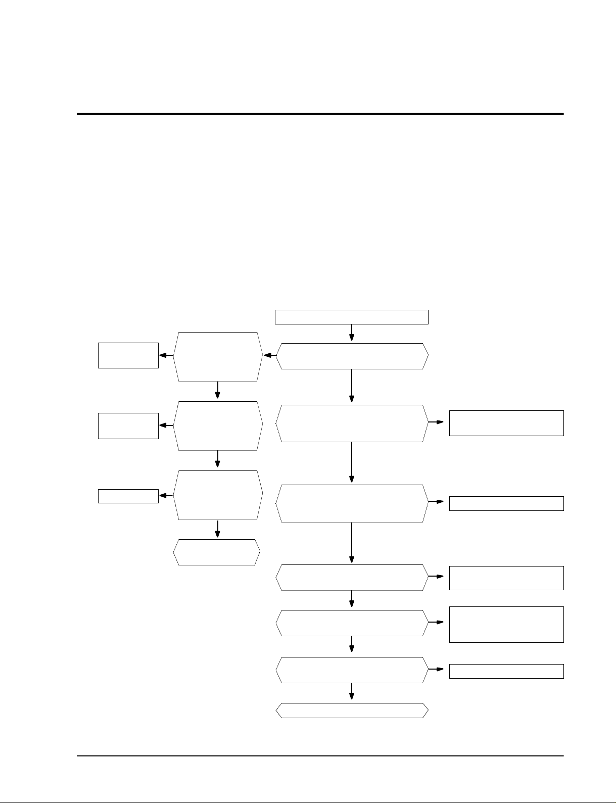
2 ) Inspection sequence
Is the operation lamp
No trouble
(normal)
Y
of indoor unit on when
the operation /stop button of remote controller
is pressed?
N
Y
Is the operation lamp flickering with the
Apply the power
sound of “ting”?
N
Check of remote
controller
Normal
Is the communication
N
signal of remote controller surely sent and
received ?
Y
Is there no problem
Y
between the connector
of Ass’y display PCB and
the receiving module?
N
Replace of Ass'y dis-
play PCB
Is the outdoor power connected normally?
Y
Is the fuse (F701, 250V, 3.15A) of PCB open?
N
Is the voltage at Socondary side of trans-
former of PCB (TN71)? (AC15V~AC25V)
Y
Is the output voltage of voltage regulator
IC (KA 7812) DC 10V and 12V?
Y
Is the output voltage of electrostatic voltage
regulator IC (KA 7805) DC 4.5 V - 5.5 V?
Y
N
Check of the installation method
and electrical circuit
Y
Replace the fuse (250V, 3.15 A).
N
Transformer is out of order -
replace
Repair and replace the power
N
source rectifying diode (D101-
D105) and KA7812.
N
KA7805 is out of order - replace
Samsung Electronics
Replace the main PCB of indoor unit
5-5
Page 6

Troubleshooting
5-3-2 No Power (Outdoor unit)
1 ) Inspection items
(1) Á Is the power source normal (The rating Voltage ±10% range)?
(2) Is the outdoor power connected normally? ((1) of terminal : L, (2) of terminal : N, (3) of termi-
nal : communication) ?
(3) Check whether the display of outdoor PCB(SEG1) is shown in the order of A- B - C when the
power is applied.
If the display (SEG 1) is not shown the inspection and repair shall be performed in the
sequence of the following:
2 ) Inspection sequence
Check the com-
munication of PCB
Normal of
outdoor PCB
Replace the
transformer
Measurement of resistance
N N
of power transformer
Are they as follows?
1st side 190 ~ 210Ω
Assemble the transformer
Y Y
and whether the
LED 1 is continu-
ously flickering.
N
Replace the fuse
(F701) 250V 3.15A.
2nd side 0.9 ~ 1.1Ω
Y
in the normal way.
Put the power off and put it on after 5
Is the display of PCB shown in the
Are the power cord ((1) L, (2) N) and
communication line (3) of outdoor termi-
nal block connected correctly?
Is the terminal of PCB terminal (RY71,
72, 73) are assembled in the correct
Y
Insert the primary side of power trans-
former in the terminal GT01 and then is
the voltage of secondary side normal?
Is the fuse (F101, 250V 2 A) blown out?
Check whether the output voltage of
Check whether the output voltage of
Replace the outdoor unit Ass'y main PCB.
seconds.
sequence of A-B-C?
N
Y
position?
Y
Is the fuse open? (F701)
N
(AC 15V- AC 25V)
Y
N
IC01 (KA 7812) is DC 12V.
Y
IC02 (KA 7805) is DC 5V.
Y
Reinstall the power cord and commu-
N
nication line with the reference of
installation manual.
After watching the display of PCB
N
board, assemble the color and
shape of housing correctly as follows:
BLK
BLK
WHT
RED
RED
Y
Replace the fuse F101 (250V 2 A).
Check and Replace the rectifying
N
diode of power side (D101 - D104)
N
and KA 7812.
Replace the IC 02 (KA7805)
5-6
Samsung Electronics
Page 7

Troubleshooting
5-3-3 When the fan of indoor unit does not operate
1 ) Inspection items
(1) Is the power voltage normal?
(2) Is the connector of indoor fan with the good contact? (CN73)
(3) Is the soldering status of running condenser (CR71) with the good contact?
(4) Is connector of the Hall IC with the good contact (CN 43) ?
(5) Is the indoor fan rotating when it is under operation mode?
(6) Is the FAN LED (green) flickering when the indoor fan stalled (for more than 15 seconds) and
the trouble condition of speed detecting part?
Put the power off and put it on after 5 seconds.
Y
N
If the power is not available (indoor
unit), item no 5-3-1.
N
Replace of indoor unit PCB Ass'y.
Error occurs after the
indoor unit fan motor is
rotating for 15 seconds?
(FAN Lamp flickering)
Y
Replacement of indoor
unit fan motor.
Is the operation lamp flickering for 3 minutes and
Y
If the operation /stop button of the remote controller
is pressed, is the operation lamp flickering and then
is the indoor fan rotating after 5~6 seconds?
Y
Is AC 120V and higher shown across the indoor
then put off?
Y
Y
fan connector (CN73) ?
N
N
Is the type of MICOM (IC 04) Pin no.
63 old type ?
120Hz
Y
Is the pin no. 12 of IC 06 (KID 65003)
the old type?
120Hz
Y
Is the pin no 25 of MICOM
the old type?
Replace the indoor unit PCB Ass'y due to the
Micom defect.
N
N
Replace the IC 06 (KID 65003) and
SS71(G3MB202pl).
Replace Q401 (Ksc 945Y).
Samsung Electronics
5-7
Page 8

Troubleshooting
5-3-4 When the outdoor unit fan does not operate
1 ) Inspection items
(1) The outdoor unit fan motor operates only when the operating conditions are satisfied and is
selected by the RY74(LOW) and PY75(HI) to ro t a t e .
(2) Is the power voltage normal?
(3) Is the contact of outdoor unit fan motor (CN 73) good?
(4) Is the winding resistance of outdoor unit fan motor 58Ω at Hi side and 143Ω at low side?
(5) The outdoor unit fan motor operates with Hi at over 28°C and low at below 26°C during the
cooling operation, and operates with Hi at below 14°C and low at over 15°C during the heating
o p e r a t i o n .
2 ) Inspection sequence
Apply the power to the outdoor unit and operate the indoor unit.
Is the indoor unit under operating conditions?
Y
Is it operating in the High speed?
N
Is the voltage shown across the connector (1)↔(3)
((1)↔(5))(AC 198V- AC 264V)?
N
Is no. 11 ( 12) of IC 06 at low? (DC 0.7 V)
N
Is pin no. 48(49) of IC 04 (MICOM) at High (DC 5 V)?
N
Is the outdoor unit fan motor under the operating
conditions?
N
Normal
N
Y
Y
Y
Y
Y
Check the winding resistance of outdoor unit fan
Defect of IC 04(MICOM) - replace the IC 04 or PCB
Normal (operation off)
Normal
motor winding resistance → Replace
Contact bad of RY 74(Low), RY 75(High)
→ Replace
Defect of IC06 output
→ Replace
ass’y
* Operating specification of the FAN of outdoor unit
(1) When the COMP is under the COMP ON condition during the cooling and heating operation,
Hi or LOW operation is selected according to the temperature condition of outdoor ro o m .
(2) When A room and B room are mixed to operate , it is always under low operation.
(3) Perform the comp ON/OFF control in the dry mode.
(4) When it is under the operation of anti-freezing, overload protection, defrost operation, it may
be Low, high or Off .
(5) Hi = High speed, Low = Low speed
5-8
Samsung Electronics
Page 9

5-3-5 When the UP/DOWN Louver Moter Does Not Operate. (Initial Diagnosis)
1) Checklist :
(1) Is input voltage normal?
(2) Is the UP/DOWN louver motor properly connected with the connector (CN61)?
2 ) Troubleshooting pro c e d u re
Remove power cord and plug in again in approx. 5 seconds.
Troubleshooting
Is operating lamp blinking?
Y
Does operation start when swing button of the remote con-
trol unit pushed?
N
Voltage at pin #33-#36 of micom (ICO4)
change?(Squarewave)
Y
Volatge at pin #13, #14, #15, #16 of IC05 (KID65003)
change?(Squarewave)
Y
UP/DOWN louver motor is faulty.
Y
Check as in the procedure "No Power
parts". Refer to page 5-6.
Y
N
N
Driver IC05 (KID65003) is faulty.
Normal
Micom (IC04) is faulty.
Samsung Electronics
5-9
Page 10

Troubleshooting
5-3-6 If Operation By Remote Control Unit Is Impossible. (Initial Diagnosis)
1) Troubleshooting pro c e d u re
Remove power cord and plug in again approx. 5 Seconds
Is operation lamp blinking?
Y
“ “ sound heard from the indoor unit when
ON/OFF button on the remote control unit pushed?
N
Voltage of battery less than 2.5V (Remote Control Unit)?
N
LCD display status of REMOCON normal?
Y
Transmission display lamp ( ) blinking when
ON/OFF button on the remote control unit pushed?
Y
Voltage at PIN #30 of Remocon Micom change?
Y
Voltage at collecter of Q601 or Q602 change?
Y
N
Check as in the procedure “NO Power
parts”. Refer to page 5-6.
Y
Y
N
N
N
N
Normal
Replace battery.
LCD is faulty.
Replace button.
Micom is faulty.
Q601(C4375Y) or Q602(C1623Y) is faulty.
IR LED(CL-1L5EU) is faulty.
5-10
Voltage at pin #26 of micom (IC04) change (INDOOR UNIT)?
Y
Micom (IC04) is faulty.
N
Receiver module is faulty.
Samsung Electronics
Page 11

5-3-7 When the 4 way valve (A,B) is not operating
1. Inspection items
(1) A re the 4 way valve A and B under the operating conditions?
(When the COMP A (4 way valve A ) and COMP B (4 way valve B) are on during the
heating operating)
(2) Is the power voltage normal?
(3) Is the connecting of 4 way valve A (CN 75) and B (CN 76) good?
2) Inspection sequence
Put off the outdoor unit power and put it on again after 5 seconds.
Select the heating operation of A(B) room by the remote controller.
Troubleshooting
Has 3 minutes passed after selection of A(B) room heating?
Y
Is the 4 way valve A(B) on?
N
Is the voltage shown across the 4 way valve A(B) connector
(CN 75, CN 76) ?
N
Is the pin no 47(46) of IC 04 ( MICOM) at high (DC 5V) ?
N
Is the 4 way valve A (B) under operating conditions?
N
Normal
N
Y
Y
Y
Y
Defect of RY 76 (RY 77) contact and coil →Replace
Defect of IC 06 (IC 07 ) output →Replace
Defect of IC 04(MICOM) - replace the IC 04 or PCB
Keep 4 way valve off.
Normal
the Relay
ass’y
*4 way valve operating conditions
(1) During the defrost control, put the 4 way valve A(B) off .
(2) During the heating operation put the 4 way valve A(B) on.
(3) The changeover of heating to cooling : put the 4 way valve off immediately (in case of B and C
ro o m ) .
(4) The changeover of cooling to heating : it is on after 170 seconds delay.
Samsung Electronics
5-11
Page 12

Troubleshooting
5-3-8 When the compressor does not operate
1) Inspection items
(1) Is the COMP A under the operating conditions? (cooling operating of A, B(C) ro o m )
(2) Is the power voltage normal? (AC 198- AC 264V)
(3) A re the connector connection of COMP A ( RY 72, 73) and B(RY 71) good?
(4) The COMP A(B) is operated on and off in accordance with the operating conditions of indoor
unit of A (B. C) room.
2) Inspection sequence
Apply the outdoor power and operate the indoor unit A(B.,C)
in the cooling mode.
Y
Has 3 minutes passed COMP A(B) after the power initial
and COMP on/off
Y
Is comp A (B) on?
N
*Refer to the power measuring terminal
Is the voltage (AC 198- AC264V) shown across the terminal
of Comp A(B) power applied?
N
Is the voltage of pin no. 14, 13( 15) at low
(DC 0.7V)?
N
Is the voltage of pin no. 50, 51 (52) of IC 04 (micom) at
high (DC 5V)?
N
Is comp A (B ) under the operating condition?
N
N
Normal (comp A (B ) off) Is the comp A under the operating condition?
N
Y
Y
Defect of comp A (B) and running condenser
Keep Comp A (B ) off
Normal
→ Replace
Y
Defect of Ry 72, 73 (Comp B) and Ry 71(comp A) con-
tact and coil → Replace
Y
Defect of IC 06 output
→ Replace
Y
Defect of Ic 04 (micom)
→ Replace
Normal
(comp A (B ) off)
* Comp A (B ) operating conditions
(1) Comp A : Comp on /off control in accordance with the A room during the heating and cooling
indoor unit operation
(2) Comp B : Comp on /off control in accordance with the B(C) room during the heating and cool-
ing indoor unit operation
BLK
RY72
(4)
* Comp A(B ) power measuring terminal
(1) Comp A measuring ; RY 73 (4) ↔ RY 72 (4)
(2) Comp B measuring ; RY 71 (4) ↔ RY 72 (4)
(3) Power input ; RY 72 (3) ↔ RY 7 3 ( 3 )
5-12
RED
(3)
RY71
(3)
RY73
(3) (4)
BLK
(4)
WHT
RED
Samsung Electronics
Page 13

5-4 PCB Inspection
5-4-1 Cautions for Part Replacement
1 . The human body carries much static
e l e c t r i c i t y. Before touching a part for re p a i r,
replacement or the similar purpose, be sure
to touch a grounded metallic portion by
hand to let the static electricity go thro u g h
the matallic portion to the earth.
Espectially when handling any micro
computer or IC, carefully remove such static
electricity before touching them.
2 . When repairing any part on a work bench,
be sure to place an insulative sheet on the
bench and always keep the sheet surface
neat without any metal fragments. If any
such fragment touches a part, a secondary
t rouble will possibly be caused in the part.
3. B e f o re replacing any parts, be sure to turn
o ff the power supply. If such replacement is
done with the power supply kept on, an
electric shock, short circuit or destruction of
a part may re s u l t .
4. During replacement or repair of a part,
c a refully handle it : The printed circ u i t
b o a rd has fine lead wires (jumper wires) and
glass-made parts (diode) on its substrate.
So if a circuit board is roughly handled, such
lead wires and parts will be easily broken or
damaged by bending or shock.
5 . When soldering the lead wires of any new
part, be sure to polish them using an emery
paper or the like before solding them.
Since the lead wires of any new part are
c o v e red with an oxide film, solder cannot
a d h e re to the lead wires if not polished.
6 . When soldering any part, care should be
e x e rcised not to apply any high-wattage
soldering iron to the part for a long time.
Some parts are of so low a heat re s i s t a n c e
that they may be broken or have the
p roperties changed if a soldering iron is so
applied (Otherwise, the pattern may
possibly be separated and raised).
7. The heat of the soldering iron should be
t r a n s f e red to the entire object to be soldere d .
If the solder pieces are not well fused due to
i n s u fficient transfer of the heat from the
soldering iron, no satisfactory electrical
continuity can be assured even if the
s o l d e red objects appear well connected to
each other.
8 . The solder used should be limited to a
minimum. If excessive solder is used, it will
cause inter-pattern contact, which may
cause malfunction of the circ u i t .
5-4-2 Procedure
The parts should be replaced in the following pro c e d u re .
Check for any faulty part.
Detach the faulty part.
Replace it with a new part.
Check the operation of the new part.
The repair is completed.
Samsung Electronics
5-13
Page 14

Troubleshooting
5-4-3 Detailed Procedure
No.
Pull out the power plug from the
1
AC terminal and confirm the fuse
on the PCB assembly
Turn the power on.
2
If lamp blinks trouble is not
related to the items 1 through 4
on the right.
Set TURBO operating mode when
3
RMC switch pushed after a delay
of 3 minutes.
(A-unit and B-unit)
Malfunction
Checking point (symptoms)
1. Is the broken?
Voltage check
1. AC voltage at both end of transformer Primary?
198 - 264V~
2. AC voltage at both end of transformer secondary?
14- 18Vac
3. DC voltage at OUT and GND of IC01
(KA7812)? 12VDC
4. DC voltage at OUT and GND of IC02? 5VDC
5. DC voltage at Q201 Base and GND change?
squarewave
Voltage check
1. Voltage of relay (RY71, 72, 73) coil Voltage at
pin#13, 14, 15 of IC07 : 12VDC
Causes
1. Voltage over
2. Indoor unit fan motor short-circuit.
1. Irregular power code or power fuse,
or poor wiring.
2. Transformer is faulty.
3. Power circuit is faulty.
4. Power circuit is faulty.
5. Q201 is faulty.
D101~D104 (IN4007)
1. Relay(RY 71) coil is open.
IC6(KID65003A) is faulty.
Set operating mode when RMC
4
switch pushed.
1. TURBO mode
Set operating mode when
5
RMC switch pushed.
1. [FAN] mode
2. Fan speed [Hi]
3. Continuously operation
2. Voltage at RY72 No 3 and RY71 No 3 ,
RY72 No 3 and RY73 No 3 , 198- 264V~
1. Compressor does not operate.
1. Voltage at 3 5 both ends of CN73 :
above 180V~
2. Indoor unit fan motor does not operate.
2. Relay contactor is faulty or Relay is
faulty
1. Temperature of Heat exchange
is lower.
2. PCB is faulty.
3. Room sensor or Heat exchanger
temperature sensor is faulty
1. Indoor unit fan motor is faulty.
2. Poor connection of indoor fan motor
and connector of RPM sensing (CN43)
5-14
Samsung Electronics
Page 15

5-5 Fault Diagnosis of Major Parts
Parts
Temp.Sensor
Heat ex. Sensor
Indoor Fan Motor
Diagnosis
Measure resistance with a tester.
Normal 8KΩ~27KΩ at ambient temperature (+0°C ~ +30°C)
Abnormal ∞, O Ω … open or short
Measure resistance between terminals (CN73) with a tester
Normal At ambient temperature (10°C ~ 30°C)
between Resistance
Red, Yellow 190±10Ω
Red, Blue 170±10Ω
Abnormal
Measure the voltage between ground and signal wire of the fan motor (CN43)
Normal
between Voltage
Gray, Orange 05V~4.5V
Outdoor Fan Motor
Stepping Motor
(UP/DOWN swing motor)
Yellow, Orange 5V
Abnormal Abnormal if voltage does not change from 0V to 5V.
Normal At ambient temperature (10°C ~ 30°C)
between Resistance Remark
Red, Yellow 143±10Ω Low
Blue, Red 58±10Ω High
Abnormal ∞, O Ω … open or short
Measure resistance between red wire and each terminal.
Normal Approx. 380Ω at ambient temperature (20°C ~30°C)
Abnormal ∞, O Ω … open or short
Samsung Electronics
5-15
 Loading...