

Samsung AC090FCASEH, AC090FCADEH, AC100FCADEH, AC100FCASEH, RC090SHXEA Installation Manual
...
ACFCADEH/ACFCADGH
ACFCAPEH/ACFCAPGH
ACFCAFEH/ACFCASEH
RCDHXE/RCDHXG
RCPHXEA/RCPHXGA
RCZHXEA/RCSHXEA
ACHCAPKH/ACHCAPNH
ACHCADKH/ACHCADNH
ACJXADH/ACJXADEH1
Air Conditioner
installation manual
ENITESPTFR
imagine the possibilities
Thank you for purchasing this Samsung product.
DE
EL
DB98-32793A-25
Contents
Safety precautions ..........................................................................................................3
Preparation for outdoor unit installation.....................................................................................5
Deciding on where to install the outdoor unit ...............................................................................6
Outdoor unit installation ..................................................................................................10
Connecting the cable .....................................................................................................11
Connecting the refrigerant pipe . . . . . . . . . . . . . . . . . . . . . . . . . . . . . . . . . . . . . . . . . . . . . . . . . . . . . . . . . . . . . . . . . . . . . . . . . . . . . . . . . . . . . . . . . . . 21
Adding refrigerant (R-410A) ...............................................................................................22
Installing DPM ............................................................................................................25
Connecting up and removing air in the circuit .............................................................................26
Cutting/Flaring the pipes.................................................................................................. 28
Performing leak tests...................................................................................................... 29
Connecting the drain hose to the outdoor unit ............................................................................29
Refrigerant pipe work .....................................................................................................30
Using stop valve ..........................................................................................................32
Interface module Installation (Optional) ...................................................................................33
Pump down Procedure....................................................................................................34
Checking correct grounding............................................................................................... 35
Testing operations ........................................................................................................36
COMMISSION DELEGATED REGULATION (EU) No 626/2011
Troubleshooting ..........................................................................................................61
i)...............................................................................................................
39
Correct Disposal of This Product
(Waste Electrical & Electronic Equipment)
(Applicable in countries with separate collection systems)
This marking on the product, accessories or literature indicates that the product and its electronic accessories (e.g.
charger, headset, USB cable) should not be disposed of with other household waste at the end of their working life. To
prevent possible harm to the environment or human health from uncontrolled waste disposal, please separate these
items from other types of waste and recycle them responsibly to promote the sustainable reuse of material resources.
Household users should contact either the retailer where they purchased this product, or their local government oce,
for details of where and how they can take these items for environmentally safe recycling.
Business users should contact their supplier and check the terms and conditions of the purchase contract. This product
and its electronic accessories should not be mixed with other commercial wastes for disposal.
2
Safety precautions
Carefully follow the precautions listed below because they are essential to guarantee the safety of the equipment.
• Always disconnect the air conditioner from the power supply before servicing it or
WARNING
General information
Carefully read the content of this manual before installing the air conditioner and store the manual in a safe place in order
to be able to use it as reference after installation.
For maximum safety, installers should always carefully read the following warnings.
Store the operation and installation manual in a safe location and remember to hand it over to the new owner if the air
conditioner is sold or transferred.
This manual explains how to install an indoor unit with a split system with two SAMSUNG units. The use of other types
of units with dierent control systems may damage the units and invalidate the warranty. The manufacturer shall not be
responsible for damages arising from the use of non compliant units.
The manufacturer shall not be responsible for damage originating from unauthorized changes or the improper
connection of electric and requirements set forth in the “Operating limits” table, included in the manual, shall
immediately invalidate the warranty.
The air conditioner should be used only for the applications for which it has been designed: the indoor unit is not suitable
to be installed in areas used for laundry.
Do not use the units if damaged. If problems occur, switch the unit o and disconnect it from the power supply.
In order to prevent electric shocks, res or injuries, always stop the unit, disable the protection switch and contact
SAMSUNG’s technical support if the unit produces smoke, if the power cable is hot or damaged or if the unit is very noisy.
Always remember to inspect the unit, electric connections, refrigerant tubes and protections regularly. These operations
should be performed by qualied personnel only.
The unit contains moving parts, which should always be kept out of the reach of children.
Do not attempt to repair, move, alter or reinstall the unit. If performed by unauthorized personnel, these operations may
cause electric shocks or res.
Do not place containers with liquids or other objects on the unit.
All the materials used for the manufacture and packaging of the air conditioner are recyclable.
The packing material and exhaust batteries of the remote controller(optional) must be disposed of in accordance with
current laws.
The air conditioner contains a refrigerant that has to be disposed of as special waste. At the end of its life cycle, the air
conditioner must be disposed of in authorized centers or returned to the retailer so that it can be disposed of correctly
and safely.
This appliance is not intended for use by persons (including children) with reduced physical, sensory or mental
capabilities, or lack of experience and knowledge, unless they have been given supervision or instruction concerning use
of the appliance by a person responsible for their safety. Children should be supervised to ensure that they do not play
with the appliance.
For use in Europe : This appliance can be used by children aged from 8 years and above and persons with reduced
physical, sensory or mental capabilities or lack of experience and knowledge if they have been given supervision or
instruction concerning use of the appliance in a safe way and understand the hazards involved. Children shall not play
with the appliance. Cleaning and user maintenance shall not be made by children without supervision.
accessing its internal components.
• Verify that installation and testing operations are performed by qualied personnel.
• Verify that the air conditioner is not installed in an easily accessible area.
ENGLISH
3

Safety precautions
Installing the unit
IMPORTANT: When installing the unit, always remember to connect rst the refrigerant tubes, then the electrical lines.
Upon receipt, inspect the product to verify that it has not been damaged during transport. If the product appears
damaged, DO NOT INSTALL it and immediately report the damage to the carrier or retailer (if the installer or the
authorized technician has collected the material from the retailer.)
After completing the installation, always carry out a functional test and provide the instructions on how to operate the air
conditioner to the user.
Do not use the air conditioner in environments with hazardous substances or close to equipment that release free ames
to avoid the occurrence of res, explosions or injuries.
Our units should be installed in compliance with the spaces shown in the installation manual, to ensure accessibility from
both sides and allow repairs or maintenance operations to be carried out. The unit’s components should be accessible
and easy to disassemble without endangering people and objects.
For this reason, when provisions of the installation manual are not complied with, the cost required to access and repair
the units (in SAFETY CONDITIONS, as set out in prevailing regulations) with harnesses, ladders, scaolding or any other
elevation system will NOT be considered part of the warranty and will be charged to the end customer.
Power supply line, fuse or circuit breaker
Always make sure that the power supply is compliant with current safety standards. Always install the air conditioner in
compliance with current local safety standards.
Always verify that a suitable grounding connection is available.
Verify that the voltage and frequency of the power supply comply with the specications and that the installed power is
sucient to ensure the operation of any other domestic appliance connected to the same electric lines.
Always verify that the cut-o and protection switches are suitably dimensioned.
Verify that the air conditioner is connected to the power supply in accordance with the instructions provided in the
wiring diagram included in the manual.
Always verify that electric connections (cable entry, section of leads, protections…) are compliant with the electric
specications and with the instructions provided in the wiring scheme. Always verify that all connections comply with
the standards applicable to the installation of air conditioners.
Devices disconnected from the power supply should be completely disconnected in the condition of overvoltage
category.
Always disassemble the electric lines before the refrigerant tubes.
4
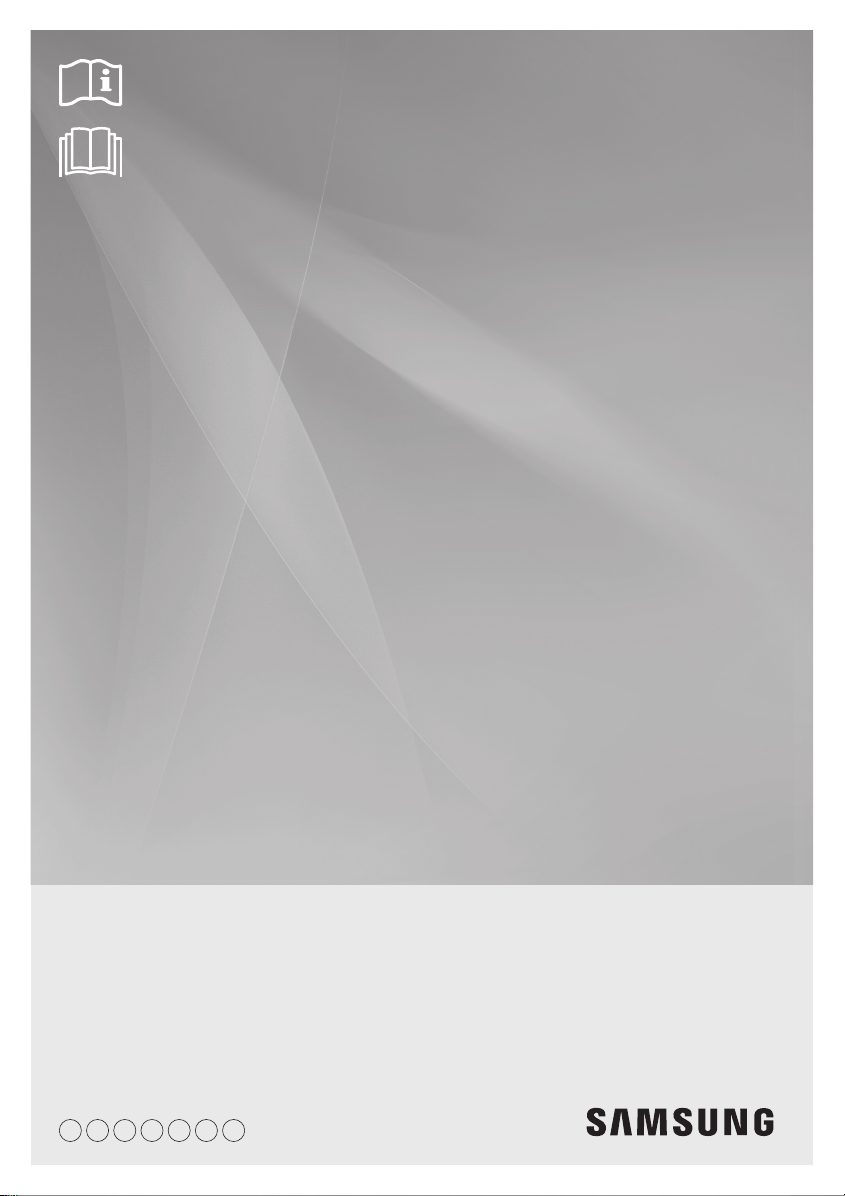
Preparation for outdoor unit installation
The air conditioner uses R-410A refrigerant.
A Type
Heat pump
AC090FCAEH/AC100FCADH/AC100FCASEH/RC090HXEA/RC100DHXA/RC100SHXEA/AC071HCAPKH/
AC090HCADH/AC100HCADH/AC120HCADH/AC100JXADH/AC120JXADH/AC100JXADEH1
620
384
330
940
360
998
(Unit : mm)
537
528
ENGLISH
675
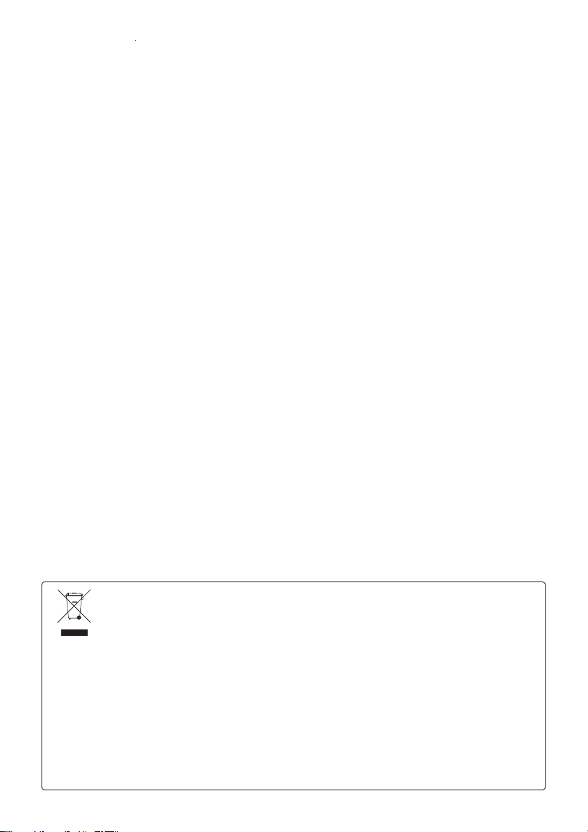
B Type
Heat pump
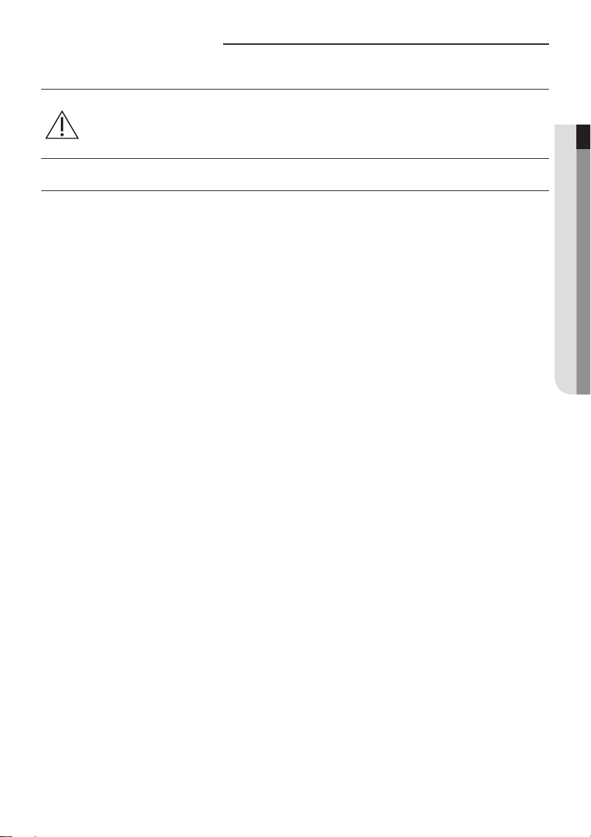
C Type
Heat pump
AC100FCAPH/RC100DHXEH/RC100PHXA/RC100DHXEG/RC125HX/RC125DHXEG/RC140DHXEB/RC140DHXGA/
AC090HCAPKH/AC140HCADH/AC140JXADH
AC100FCAFH/RC100ZHXEA/RC140PHXA/RC140DHXEH/RC140DHXEG/RC155DHXEH/RC155DHXEG/RC180DHXGH/
RC180DHXGG/AC100HCAPH/AC120HCAPH/AC140HCAPH
620
330
940
1395
360
1420
384
1095
558
567
5
Preparation for outdoor unit installation
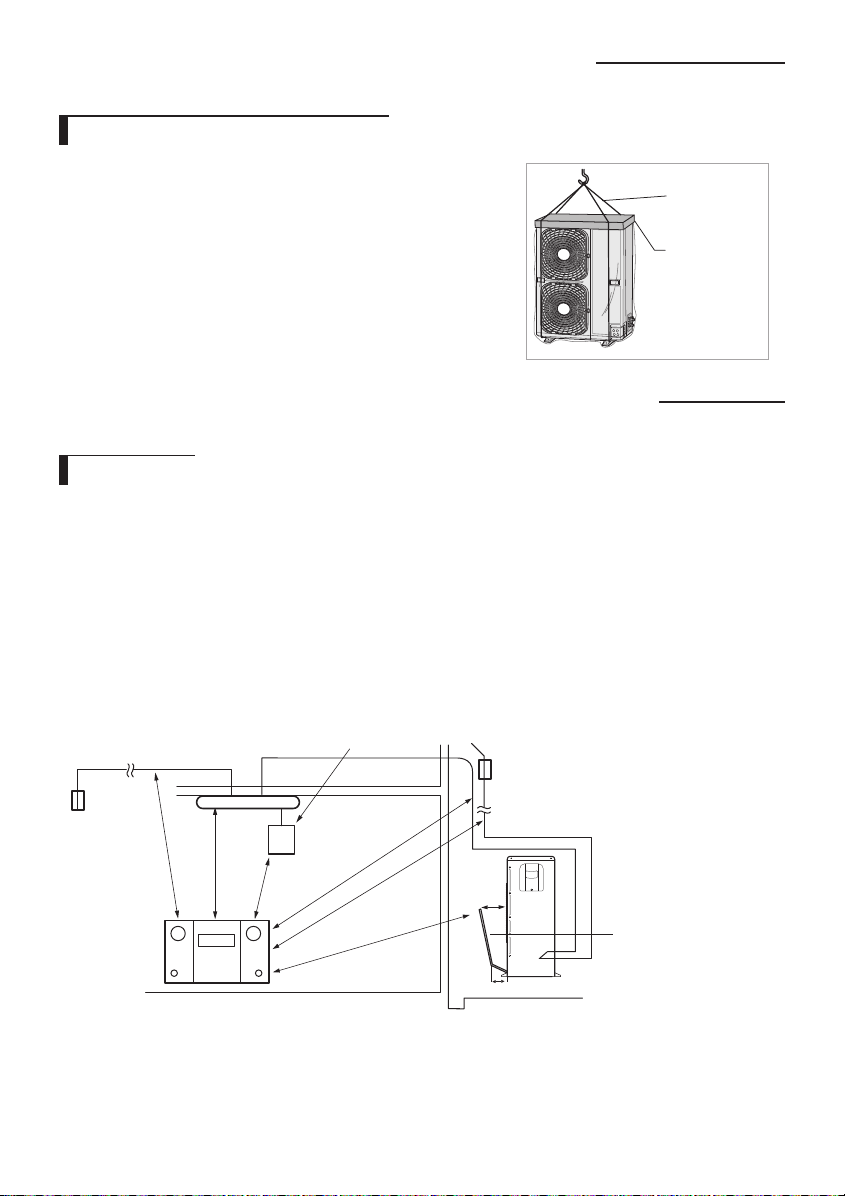
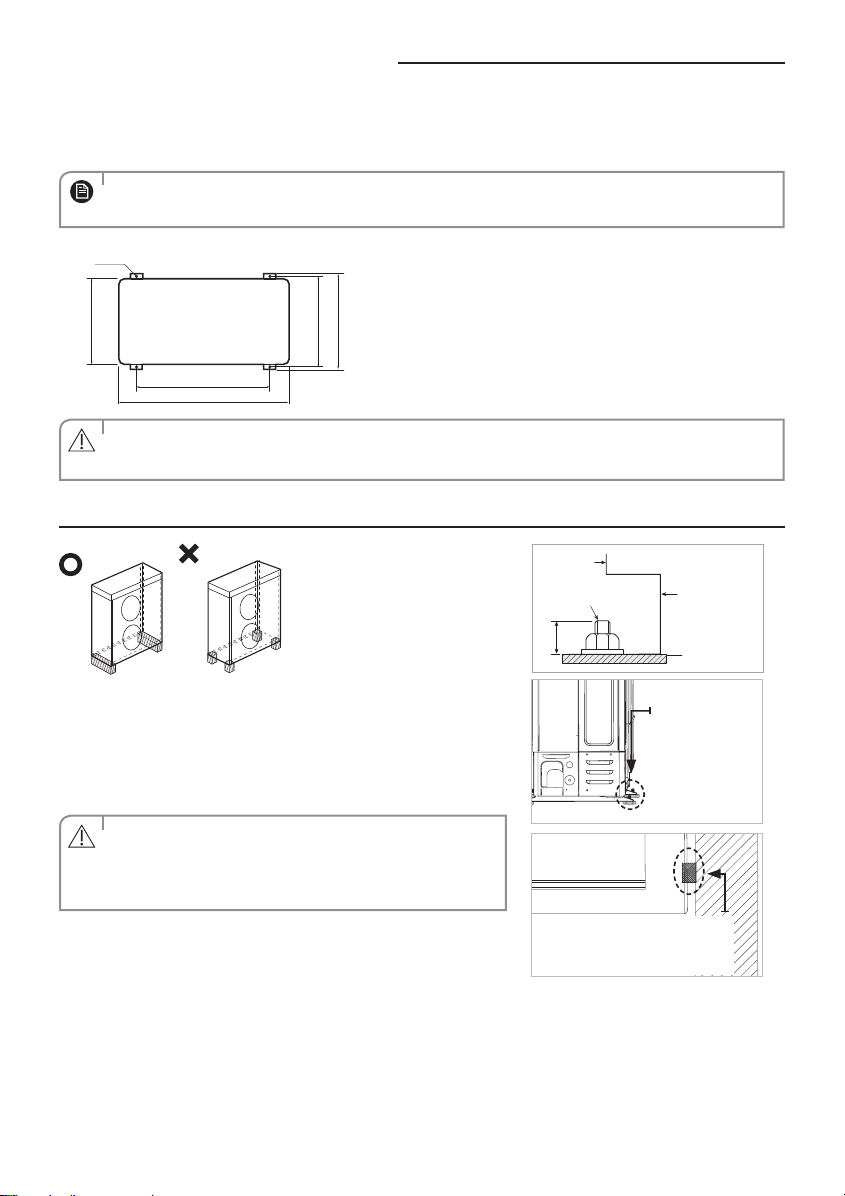
Moving the Outdoor Unit by Wire Rope
Fasten the outdoor unit by two 8m or longer wire ropes as shown at the
gure. To prevent from damage or scratches, insert a piece of cloth between
the outdoor unit and rope, then move the unit.
The appearance of the unit may be dierent from the picture depending
on the model.
Wire rope
Plate protection
cloth
Deciding on where to install the outdoor unit
Outdoor Unit
The outdoor unit must not be placed on its side or upside down, as the compressor lubrication oil will run into the cooling
circuit and seriously damage the unit.
Choose a location that is dry and sunny, but not exposed to direct sunlight or strong winds.
Do not block any passageways or thoroughfares.
Choose a location where the noise of the air conditioner when running and the discharged air do not disturb any
neighbours.
Choose a position that enables the pipes and cables to be easily connected to the indoor unit.
Install the outdoor unit on a at, stable surface that can support its weight and does not generate any unnecessary noise
and vibration.
Position the outdoor unit so that the air ow is directed towards the open area.
Maintain sucient clearance around the outdoor unit, especially from a radio, computer, stereo system, etc.
Indoor Unit
Control
Fuse
Fuse
1m or more
1.5m or more
If the outdoor unit is installed at a height, ensure that its base is rmly xed in position.
Make sure that the water dripping from the drain hose runs away correctly and safely.
1m or more
Stereo
1.5m or more
1.5m or more
1.5m or more
Outdoor Unit
300mm
200mm
6
Air Guide Duct
(This product is not
provided by Samsung)
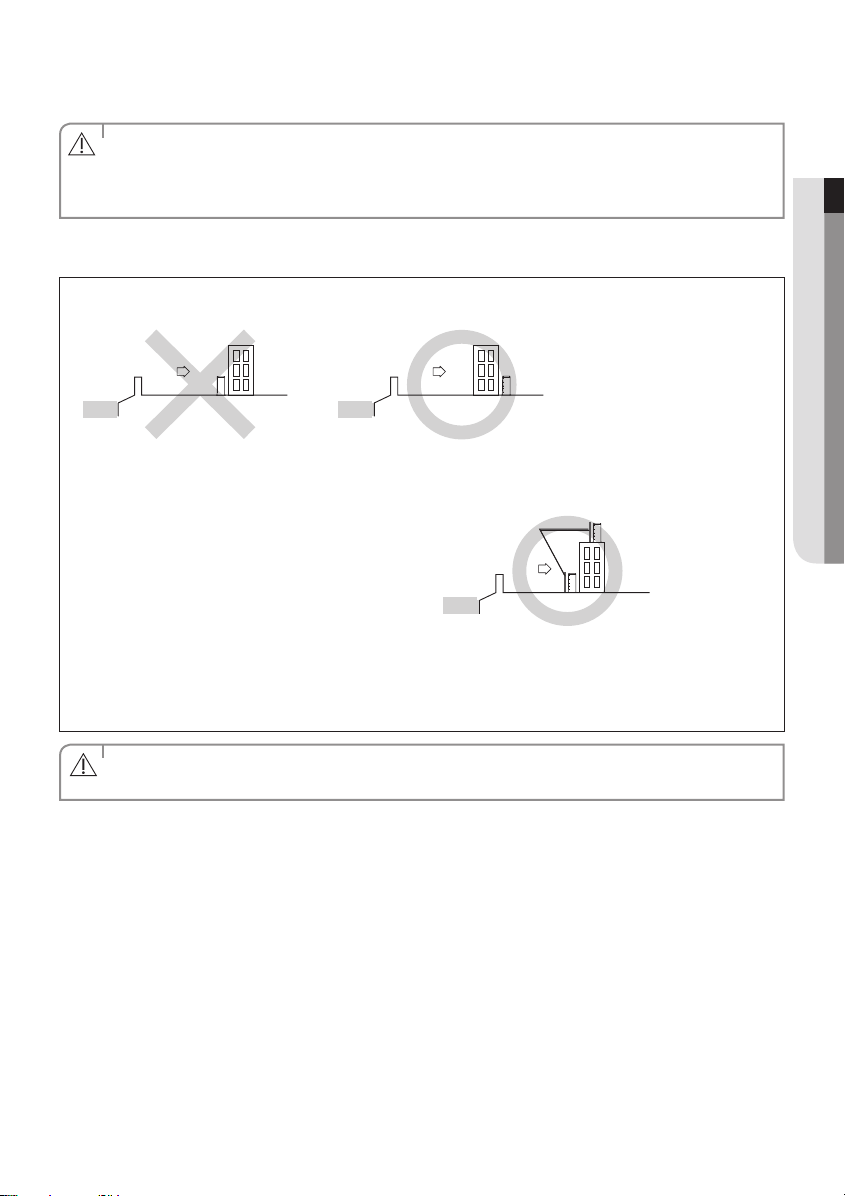
When you install the outdoor unit at wayside, you should install it above 2m height or make sure that the heat from the
outdoor unit shouldn't be in direct contact with passersby. (The ground for application :The revision of regulation for
facility in building by the law of the Ministry of Construction and Transportation.
• You have just purchased a system air conditioner and it has been installed by your installation specialist.
• This device must be installed according to the national electrical rules.
CAUTION
• With an outdoor unit having net weight upper than 60kg, we suggest do not install it suspended on wall, but
considering oor standing one.
When installing the outdoor unit near seashore, make sure it is not directly exposed to sea breeze. If you can not nd a
adequate place without direct see breeze, protection wall should be constructed.
- Install the outdoor unit in a place (such as near buildings etc.) where it can be prevented from sea breeze which can
damage the outdoor unit.
Outdoor unit
Sea breeze Sea breeze
Outdoor unit
ENGLISH
Sea
Sea
- If you cannot avoid installing the outdoor unit by the seashore, construct a protection wall around to block the sea
breeze.
• Protection wall should be constructed with a solid
material such as concrete to block the sea breeze
and the height and the width of the wall should be
1.5 times larger than the size of the outdoor unit.
Protection wall
Sea breeze
Outdoor unit
Also, secure over 700mm between the protection
wall and the outdoor unit for exhausted air to
Sea
ventilate.
- Install the outdoor unit in a place where water can drain smoothly.
• If you cannot nd a place satisfying above conditions, please contact manufacturer. Make sure to clean the sea water
and the dust on the outdoor unit heat exchanger and spread corrosion inhibitor on heat exchanger. (At least one time
per one year.)
• Depending on the condition of power supply, unstable power or voltage may cause malfunction of the parts or
control system. (At the ship or places using power supply from electric generator, etc).
CAUTION
7
Deciding on where to install the outdoor unit
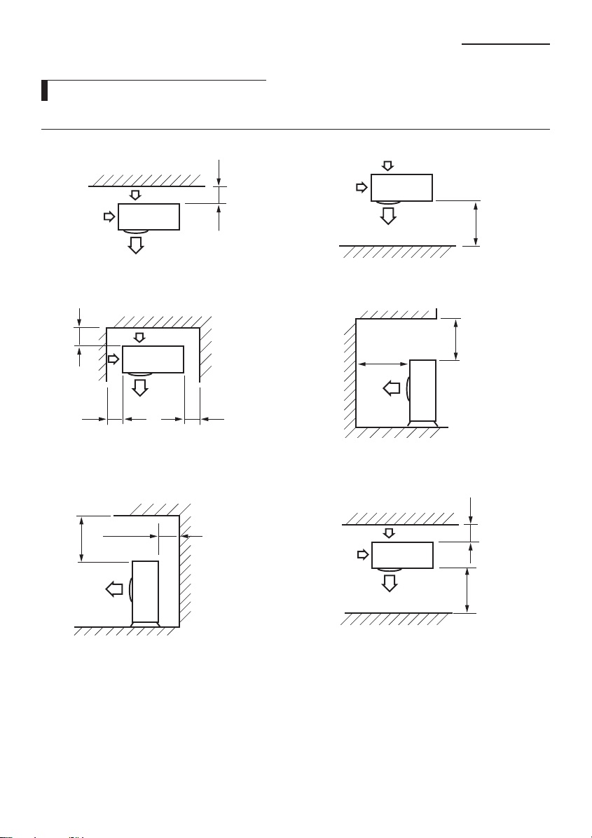
Space Requirements for Outdoor Unit
When installing 1 outdoor unit
300 or more
When the air outlet is opposite the wall When the air outlet is towards the wall
(Unit : mm)
1500 or more
300 or more
300 or more
When 3 sides of the outdoor unit are blocked by the wall The upper part of the outdoor unit and the air outlet is
300 or more
600 or more
The upper part of the outdoor unit and the air outlet is
opposite the wall
600 or more
towards the wall
When front and rear side of the outdoor unit is towards
the wall
2000 or more
1500 or more
300 or more1500 or more
8
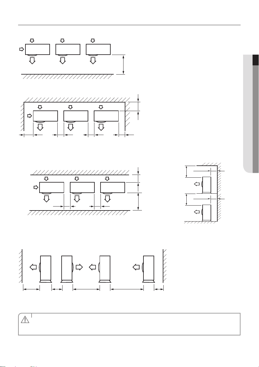
When installing more than 1 outdoor unit
When the air outlet is towards the wall
300 or more 600 or more 600 or more 600 or more
When 3 sides of the outdoor unit are blocked by the wall
(Unit : mm)
ENGLISH
1500 or more
300 or more
300 or more
500 or more
300 or more
500 or more
600 or more
300 or more1500 or more
600 or more
When front and rear side of the outdoor unit is towards the wall The upper part of the outdoor unit and
the air outlet is towards the wall
1500 or more 600 or more 3000 or more 300 or more3000 or more
When front and rear side of the outdoor unit is towards the wall
• The units must be installed according to distances declared, in order to permit accessibility from each side, either
to guarantee correct operation of maintenance or repairing products.
CAUTION
The unit’s parts must be reachable and removable completely under safety condition (for people or things).
9
Outdoor unit installation
620
940
330
360
384
The outdoor unit must be installed on a rigid and stable base to avoid any increase in the noise level and vibration, particularly if the outdoor unit is
to be installed in a location exposed to strong winds or at a height, the unit must be xed to an appropriate support(wall or ground).
Fix the outdoor unit with anchor bolts.
• The anchor bolt must be 20mm or higher from the base surface.
NOTE
Anchor bolt hole
(Unit : mm)
• Make a drain outlet around the base for outdoor unit drainage.
CAUTION
• If the outdoor unit is installed on the roof, you have to check the ceiling strength and waterproof the unit.
Outdoor Unit Support
Outdoor
Unit
Anchor bolt
20mm
OUTDOOR UNIT INSTALLED ON THE WALL BY RACK
Ensure the wall will be able to suspend the weight of rack and outdoor
unit ;
Install the rack close to the column as much as possible ;
Install proper grommet in order to reduce noise and residual vibration
transferred by outdoor unit towards wall.
When installing air guide duct
• Check and make sure that screws do not damage the copper
CAUTION
pipe.
• Secure air guide duct on guard fan.
Soft rubber designed to cut o
vibration from rack to wall.
(not supplied with product)
Outdoor
Unit
Support
Base Surface
Designed to
cut o residual
vibration from
outdoor unit to
rack.
(not supplied with
product)
10
Connecting the cable
Two electronic cables must be connected to the outdoor unit.
The connection cord between indoor unit and outdoor unit.
The power cable between outdoor unit and auxiliary circuit breaker.
Specially for Russian and European market, before installation, the supply authority should be consulted to determine the
supply system impendance to ensure compliance.
• During the unit installation make rst refrigerant connections and then electrical connections. If unit is
uninstalled rst disconnect electrical cables, then refrigerant connections.
CAUTION
• Connect the air conditioner to grounding system before performing the electrical connection.
• When installing the unit, you shouldn't use inter connection wire.
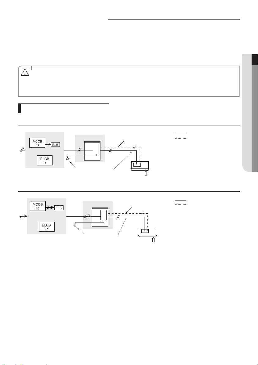
Example of Air Conditioner System
When using ELCB for 1 phase
ENGLISH
Outdoor Unit
OR
Grounding
Communication cable
Indoor Unit
Power cable
Power cable
Communication cable
When using ELCB for 3 phase 4 wires
Outdoor Unit
OR
Grounding
Communication cable
Indoor Unit
Power cable
If an outdoor unit is installed in a place in danger of an electric leak or submergence, you must install the ELCB.
Power cable
Communication cable
11
Connecting the cable
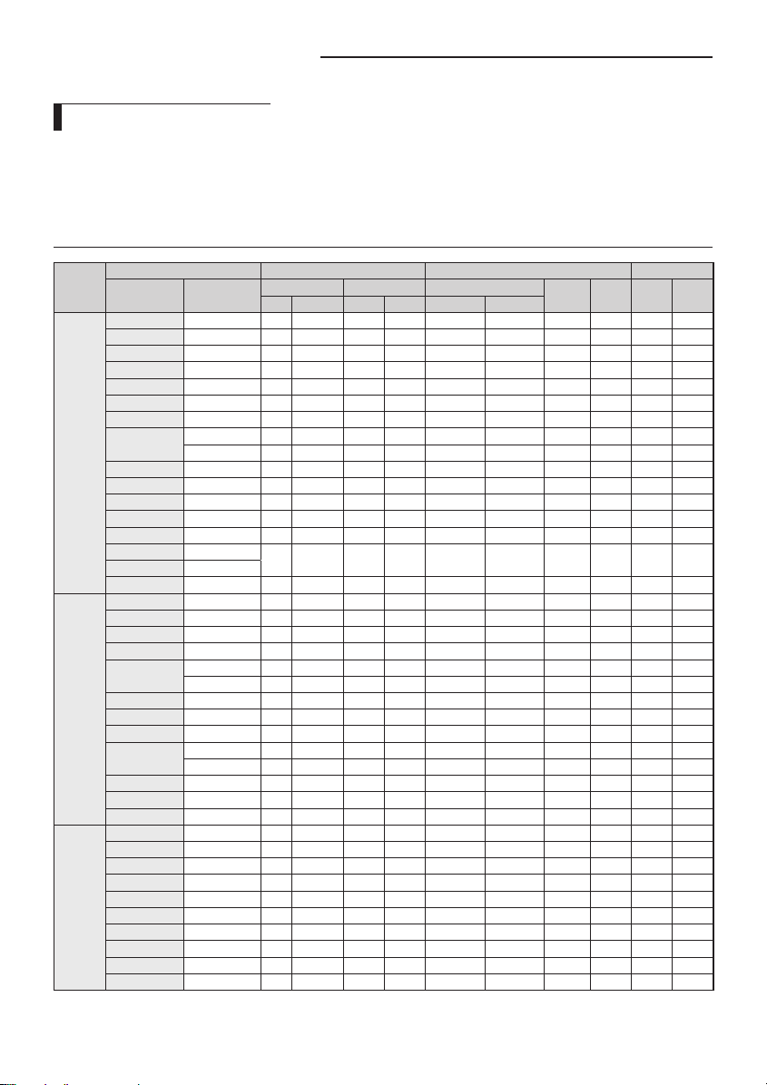
Power Cable Specications
The power cable is not supplied with air conditioner.
- Select the power supply cable in accordance with relevant local and national regulations.
- Wire size must comply with the applicable local and national code.
- Specications for local wiring power cord and branch wiring are in compliance with local cord.
Single Phase
Type of
outdoor
unit
AC090FCADEH AC090FB4DEH 50 220-240 198 264 24 24 0.7 24.7 24.7 30.0
AC090FCAPEH AC090FB4PEH 50 220-240 198 264 24 24 1.0 25.0 25.0 30.0
AC090FCASEH AC090FBMSEH 50 220-240 198 264 22 22 1.5 23.5 23.5 27.5
AC100FCADEH AC100FB4DEH 50 220-240 198 264 24 24 0.7 24.7 24.7 30.0
AC100FCASEH AC100FBMSEH 50 220-240 198 264 22 22 1.5 25.0 25.0 30.0
A
AC071HCAPKH AC071HBMPKH 50/60 220-240 198 264 24 24 2.7 26.7 26.7 30.0
AC120HCADKH AC120HBMDKH 50/60 220-240 198 264 24 24 2.7 26.7 26.7 30.0
AC100HCADKH AC100HBMDKH 50/60 220-240 198 264 24 24 2.7 26.7 26.7 30.0
AC090HCADKH AC090HBMDKH 50/60 220-240 198 264 24 24 2.7 26.7 26.7 30.0
AC100JXADEH AC100JNCDEH
AC100JXADEH1 AC100JNCDEH1
AC120JXADEH AC120JNCDEH 50 220-240 198 264 24 24 2.7 26.7 26.7 30.0
AC100FCAPEH AC100FB4PEH 50 220-240 198 264 24 24 1.0 25.0 25.0 30.0
B
AC090HCAPKH AC090HBMPKH 50/60 220-240 198 264 24 24 2.7 26.7 26.7 30.0
AC140HCADKH AC140HBMDKH 50/60 220-240 198 264 24 24 2.7 26.7 26.7 30.0
AC140JXADEH AC140JNCDEH 50 220-240 198 264 24 24 2.7 26.7 26.7 30.0
AC100FCAFEH AC100FB4FEH 50 220-240 198 264 24 24 1.0 25.0 25.0 30.0
C
AC140HCAPKH AC140HBMPKH 50/60 220-240 198 264 32 32 2.7 34.7 34.7 40.0
AC120HCAPKH AC120HBMPKH 50/60 220-240 198 264 32 32 2.7 34.7 34.7 40.0
AC100HCAPKH AC100HBMPKH 50/60 220-240 198 264 32 32 2.7 34.7 34.7 40.0
Model Outdoor Units Input Current [A] Power Supply
Outdoor Unit Indoor Unit
RC090PHXEA NS0904PXEA 50 220-240 198 264 24 24 1.0 25.0 25.0 30.0
RC090SHXEA NS090SSXEA 50 220-240 198 264 22 22 1.5 23.5 23.5 27.5
RC100DHXEA
RC100SHXEA NS100SSXEA 50 220-240 198 264 22 22 1.5 23.5 23.5 27.5
RC100PHXEA NS1004PXEA 50 220-240 198 264 24 24 1.0 25.0 25.0 30.0
RC100DHXEH NS100HHXEH 50 220-240 198 264 24 24 2.0 26.0 26.0 30.0
RC100DHXEG NS100HHXEG 50 220-240 198 264 24 24 2.0 26.0 26.0 30.0
RC125DHXEB
RC125PHXEA NS1254PXEA 50 220-240 198 264 24 24 1.0 25.0 25.0 30.0
RC125DHXEH NS125HHXEH 50 220-240 198 264 24 24 2.8 26.8 26.8 30.0
RC125DHXEG NS125HHXEG 50 220-240 198 264 24 24 2.8 26.8 26.8 30.0
RC140DHXEB
RC140PHXEA NS1404PXEA 50 220-240
RC100ZHXEA NS1004ZXEA 50 220-240 198 264 24 24 1.0 25.0 25.0 30.0
RC140DHXEH NS140HHXEH 50 220-240 198 264 32 32 3.5 35.5 35.5 40.0
RC140DHXEG NS140HHXEG 50 220-240 198 264 32 32 3.5 35.5 35.5 40.0
RC155DHXEH NS155HHXEH 50 220-240 198 264 32 32 4.6 36.6 36.6 40.3
RC155DHXEG NS155HHXEG 50 220-240 198 264 32 32 4.6 36.6 36.6 40.3
NS1004DXEA 50 220-240 198 264 24 24 0.7 24.7 24.7 30.0
NS100SDXEA 50 220-240 198 264 24 24 1.5 25.5 25.5 30.0
NS1254DXEA 50 220-240 198 264 24 24 1.0 25.0 25.0 30.0
NS125SDXEA 50 220-240 198 264 24 24 2.0 26.0 26.0 30.0
NS1404DXEA 50 220-240 198 264 24 24 1.0 25.0 25.0 30.0
NS140SDXEA 50 220-240 198 264 24 24 2.0 26.0 26.0 30.0
Rated Voltage Range Outdoor (Down_Amp)
Hz Volts Min. Max. Cooling Heating
50 220-240 198 264 22 22 2.7 24.7 24.7 30.0
198 264 32 32 1.0 33.0 33.0 40.0
Indoor Total MCA MFA
12
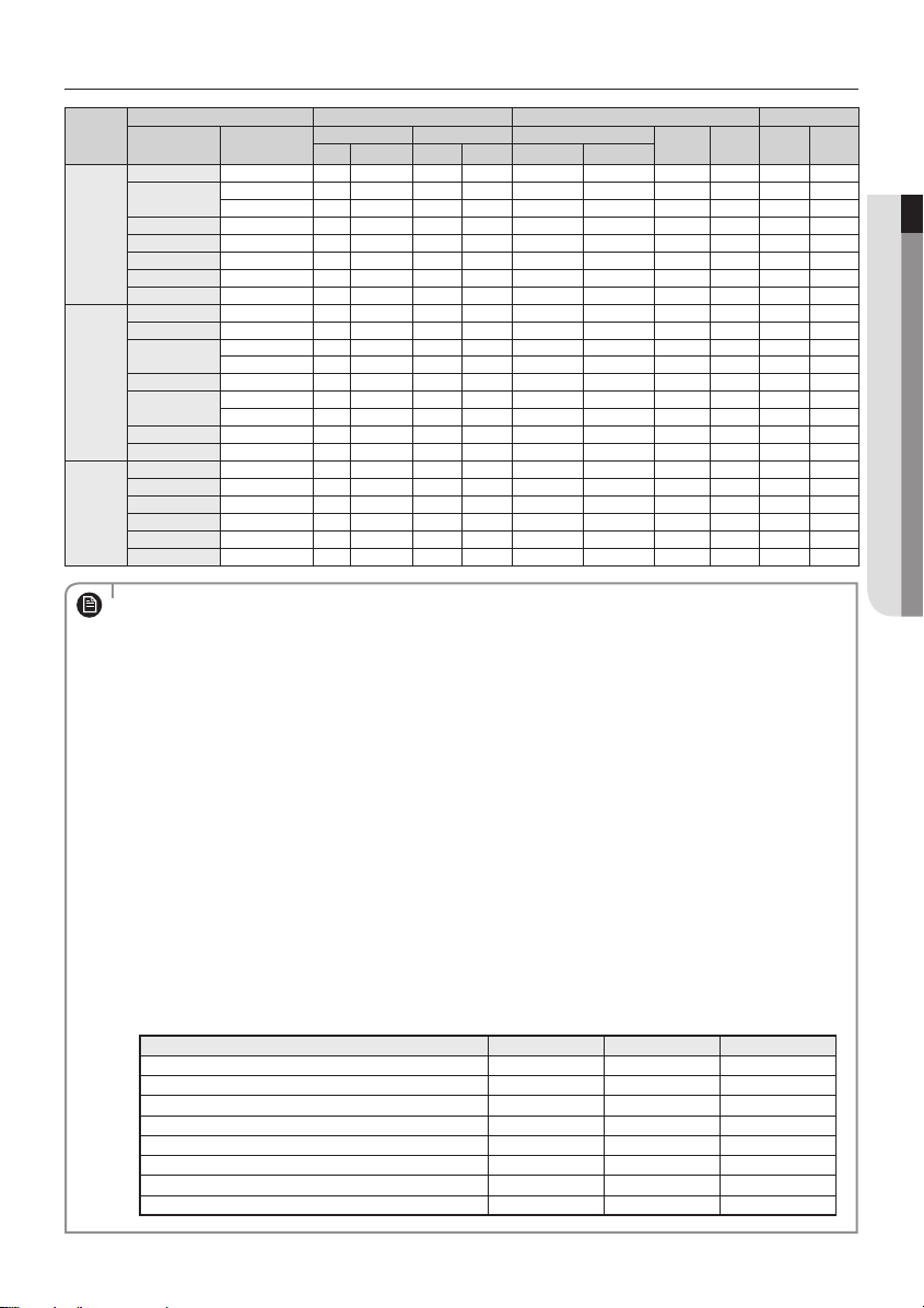
3 Phase
Type of
outdoor
unit
AC100FCADGH AC100FB4DEH 50 380-415 342 456.5 12 12 0.7 12.7 12.7 15.0
AC120HCADNH AC120HBMDKH 50/60 380-415 342 418 12 12 2.7 14.7 14.7 16.2
A
AC100HCADNH AC100HBMDKH 50/60 380-415 342 418 12 12 2.7 14.7 14.7 16.2
AC090HCADNH AC090HBMDKH 50/60 380-415 342 418 12 12 2.7 14.7 14.7 16.2
AC100JXADGH AC100JNCDEH 50 380-415 342 418 12 12 2.7 14.7 14.7 16.2
AC120JXADGH AC120JNCDEH 50 380-415 342 418 12 12 2.7 14.7 14.7 16.2
AC100FCAPGH AC100FB4PEH 50 380-415 342 456.5 12 12 1.0 13.0 13.0 15.0
B
AC140HCADNH AC140HBMDKH 50/60 380-415 342 418 12 12 2.7 14.7 14.7 16.2
AC140JXADGH AC140JNCDEH 50 380-415 342 418 12 12 2.7 14.7 14.7 16.2
C
AC140HCAPNH AC140HBMPKH 50/60 380-415 342 418 12 12 2.7 14.7 14.7 16.2
AC120HCAPNH AC120HBMPKH 50/60 380-415 342 418 12 12 2.7 14.7 14.7 16.2
AC100HCAPNH AC100HBMPKH 50/60 380-415 342 418 12 12 2.7 14.7 14.7 16.2
Model Outdoor Units Input Current [A] Power Supply
Outdoor Unit Indoor Unit
RC100DHXGA
RC100PHXGA NS1004PXEA 50 380-415 342 456.5 12 12 1.0 13.0 13.0 15.0
RC125DHXGA
RC125PHXGA NS1254PXEA 50 380-415 342 456.5 12 12 1.0 13.0 13.0 15.0
RC140DHXGA
RC140PHXGA NS1404PXEA 50 380-415 342 456.5 12 12 1.0 13.0 13.0 15.0
RC180DHXGH NS180HHXEH 50 380-415 342 456.5 12 12 2.9 14.9 14.9 16.4
RC180DHXGG NS180HHXEG 50 380-415 342 456.5 12 12 2.9 14.9 14.9 16.4
NS1004DXEA 50 380-415 342 456.5 12 12 0.7 12.7 12.7 15.0
NS100SDXEA 50 380-415 342 456.5 12 12 1.5 13.5 13.5 15.0
NS1254DXEA 50 380-415 342 456.5 12 12 1.0 13.0 13.0 15.0
NS125SDXEA 50 380-415 342 456.5 12 12 2.0 14.0 14.0 15.4
NS1404DXEA 50 380-415 342 456.5 12 12 1.0 13.0 13.0 15.0
NS140SDXEA 50 380-415 342 456.5 12 12 2.0 14.0 14.0 15.4
Rated Voltage Range Outdoor (Down_Amp)
Hz Volts Min. Max. Cooling Heating
Indoor Total MCA MFA
1. Voltage range
Units are suitable for use on electrical systems where voltage supplied to unit terminal is not below or above
NOTE
listed range limits
2. Maximum allowable voltage variation between phases is 2%.
3. Wire size & type must comply with the applicable local and national code.
Wire size : Based on the value of MCA.
Wire type : 60245 IEC57(IEC) or H05RN-F(CENELEC) grade or more.
4. MFA is used to select the circuit breaker and the ground fault circuit interrupter (earth leakage circuit breaker).
5. MCA represents maximum input current.
MFA represents capacity which may accept MCA
Abbreviations
MCA : Min. Circuit Amps. (A)
MFA : Max. Fuse Amps. (A)
6. This equipment complies with IEC 61000-3-12 provided that the short-circuit power Ssc is greater than or
equal to Ssc(*2) at the interface point between the user’s supply and the public system. It is the responsibility
of the installer or user of the equipment to ensure, by consultation with the distribution network operator if
necessary, that the equipment is connected only to a supply with a short-circuit power Ssc greater than or
equal to Ssc(*2).
[Ssc (*2)]
Model Ssc[MVA] Model Ssc[MVA]
AC140HCAPKH 2.715 AC090HCADKH 2.954
AC140HCAPNH 2.074 AC090HCADNH 2.075
AC140HCADKH, AC140JXADEH 2.996 AC120HCAPKH 3.02
AC140HCADNH, AC140JXADGH 2.064 AC120HCAPNH 2.083
AC120HCADKH, AC120JXADEH 3.365 AC100HCAPKH 3.439
AC120HCADNH, AC120JXADEH 2.086 AC100HCAPNH 2.076
AC100HCADKH, AC100JXADEH, AC100JXADEH1 3.157 AC090HCAPKH 3.299
AC100HCADNH, AC100JXADGH 2.075 AC071HCAPKH 3.329
ENGLISH
13
Connecting the cable
Between Indoor unit and Outdoor unit Connection Cable Specications(Common in use)
Power supply
Power supply Max/Min(V)
1Φ, 220-240V, 50Hz ±10%
Power supply cords of parts of appliances for outdoor use shall not be lighter than polychloroprene sheathed exible
cord. (Code designation IEC:60245 IEC 57 / CENELEC: H05RN-F or IEC:60245 IEC 66 / CENELEC: H07RN-F)
When installing the indoor unit in a computer room or net work room, use the
double shielded (Tape aluminum / polyester braid + copper ) cable of FROHH2R
type.
Indoor Power Cable
2.5mm² , 3wires
Communation Cable
0.75~1.5mm², 2wires
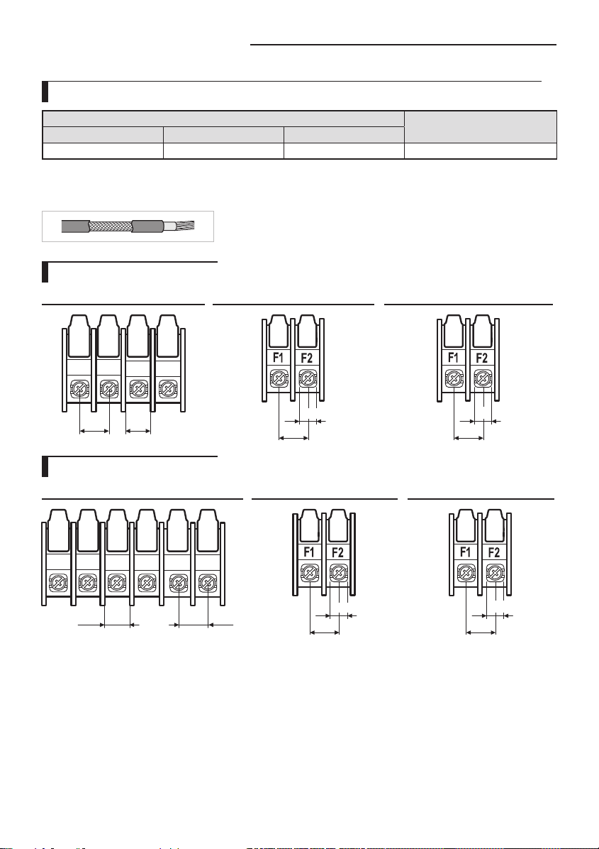
1-phase terminal block spec
AC power : M5 screw Communication : M4 screw Communication : M3 screw
1(L) 2(N)
15
L
N
12
10.1
11.4
6.7
9.7
3-phase terminal block spec
AC power : M4 screw Communication : M4 screw Communication : M3 screw
1(L) 2(N)
L1(R)
L2(S)
9.95 11.55
14
L3(T)
N
10.1
11.4
6.7
9.7

Wiring Diagram of Power Cable
ELB
MCCB
MCCB
1(L) 2(N)
N
L
N
L3(T)
1(L) 2(N)
L2(S)
L1(R)
When using ELB for 1 phase and 3 phase
Power Supply
Electrical
component box
1 phase
Communication cable
3 phase
ENGLISH
Cable tie
Indoor Power
Cable clamp
Main power cable
Indoor Unit
The appearance of the unit may be
dierent from the picture depending on
Cable tie
Cable clamp
the model.
Communication cable
Connection
cord
3 Phase 4 Wires power
cable (AC 380V)
• You should connect the power cable into the power cable terminal and fasten it with a clamp.
• The unbalanced power must be maintained within 2% of supply rating.
CAUTION
- If the power is unbalanced greatly, it may shorten the life of the condenser. If the unbalanced power is
exceeded over 4% of supply rating, the indoor unit is protected, stopped and the error mode indicates.
• To protect the product from water and possible shock, you should keep the power cable and the connection
cord of the indoor and outdoor units within ducts. (with appropriate IP rating and material selection for your
application)
• Ensure that main supply connection is made through a switch that disconnects all poles, with contact gap of a
least 3 mm.
• Devices disconnected from the power supply should be completely disconnected in the condition of
overvoltage category.
• Keep distances of 50mm or more between power cable and communication cable.
15
Connecting the cable
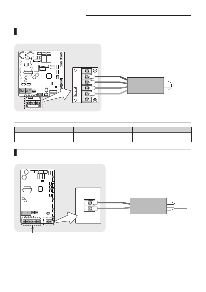
DRED wiring diagram
Outdoor unit
ASSY Control out
DRED SUB PBA
COMMON
DRM3
DRM2
DRM1
DRED Controller
Cable specication
Model Power cable Interconnection cable
RC100/125/140/155DHXEG, RC180DHXGG DRED Connected Wire
2, 0.75mm
(Only for reference)
2
H05RN-F (60245 IEC57)
Silence mode controller wiring diagram (ACHCAH/ACJXADH/AC100JXADEH1)
Outdoor unit
Silence Mode Controller
ASSY Control out
European models are not applied.
(ACHCAH/ACJXADH/AC100JXADEH1)
16

Wiring Diagram of Connection Cord
1 phase 3 phase
1(L) 2(N)
Indoor Unit
1(L)
2(N)
L1(R)
L2(S)
(AC 380V)
Outdoor Unit
L3(T)
N
Cable tie
Cable clamp
Indoor Power
Main power cable
1(L)
2(N)
1(L) 2(N)
Indoor Unit
L
N
Cable tie
Cable clamp
Outdoor Unit
F2
F1
Communication
cable
Indoor Power
3 Phase 4 Wires power cable
• Lay the electrical wiring so that the front cover does not rise up when doing wiring work and attach the
NOTE
front cover securely.
• Ground wire for the indoor unit and outdoor unit connection cable must be clamped to a soft copper
tin-plated eyelet terminal with M4 screw hole(NOT SUPPLIED WITH UNIT ACCESSORIES).
Connecting the Power Terminal
Connect the cables to the terminal board using the compressed ring terminal.
Cover a solderless ring terminal and a connector part of the power cable and then connect it.
Silver solder
F2
F1
F2F1
Communication
cable
ENGLISH
Nominal
dimensions
for cable
[mm2(inch2)]
(0.006/ 0.009)
Nominal
dimensions
Standard
for screw
dimension
[mm(inch)]
[mm(inch)]
4(3/8) 9.5(3/8)
4/6
8(3/16) 15(9/16) 9 (3/8)
10(0.01) 8(3/16) 15(9/16)
16(0.02) 8(3/16) 16(10/16)
8(3/16) 12(1/2)
25(0.03)
8(3/16) 16.5(10/16)
B D d1 E F L d2 t
Allowance
[mm(inch)]
±0.2
(±0.007)
±0.2
(±0.007)
±0.2
(±0.007)
±0.3
(±0.011)
Standard
dimension
[mm(inch)]
5.6(1/4)
7.1(1/4)
9(3/8)
11.5(7/16)
Allowance
[mm(inch)]
+0.3(+0.011)
-0.2(-0.007)
+0.3(+0.011)
-0.2(-0.007)
+0.3(+0.011)
-0.2(-0.007)
+0.5(+0.019)
-0.2(-0.007)
Standard
dimension
[mm(inch)]
3.4(1/8)
4.5(3/16)
5.8(1/4)
7.7(5/16)
Allowance
[mm(inch)]
±0.2
(±0.007)
±0.2
(±0.007)
±0.2
(±0.007)
±0.2
(±0.007)
Min.
[mm
(inch)]
6 (1/4)
7.9
(5/16)
9.5
(5/16)
11
(3/8)
Min.
Max.
[mm
[mm
(inch)]
(inch)]
5
20 (3/4) 4.3 (3/16)
(3/16)
28.5
(1-1/8)
30
9 (3/8)
(1-3/16)
13
33
(1/2)
(1-5/16)
15
(5/8)
34
(1-3/8)
13
(1/2)
Standard
dimension
[mm(inch)]
8.4 (1-3/16)
8.4 (1-3/16)
8.4 (1-3/16)
8.4 (1-3/16)
8.4 (1-3/16)
Allowance
[mm(inch)]
+0.2 (+0.007)
0(0)
+0.4 (+0.015)
0(0)
+0.4 (+0.015)
0(0)
+0.4
(+0.015) 0(0)
+0.4 (+0.015)
0(0)
(inch)]
(0.03)
(0.05)
Min.
[mm
0.9
1.15
(0.04)
1.45
1.7
(0.06)
17
Connecting the cable
Nominal
dimensions
for cable
[mm2(inch2)]
35(0.05)
50(0.07) 8(3/16) 22(7/8)
70(0.10) 8(3/16) 24(1)
Nominal
dimensions
for screw
[mm(inch)]
8(3/16) 16(10/16)
8(3/16) 22(7/8)
B D d1 E F L d2 t
Standard
dimension
[mm(inch)]
Allowance
[mm(inch)]
±0.3
(±0.011)
±0.3
(±0.011)
±0.4
(±0.015)
Standard
dimension
[mm(inch)]
13.3(1/2)
13.5(1/2)
17.5(11/16)
Allowance
[mm(inch)]
+0.5(+0.019)
-0.2(-0.007)
+0.5(+0.019)
-0.2(-0.007)
+0.5(+0.019)
-0.4(-0.015)
Standard
dimension
[mm(inch)]
9.4(3/8)
11.4(7/16)
13.3(1/2)
Allowance
[mm(inch)]
±0.2
(±0.007)
±0.3
(±0.011)
±0.4
(±0.015)
Min.
[mm
(inch)]
12.5
(1/2)
17.5
(11/16)
18.5
(3/4)
Min.
Max.
[mm
[mm
(inch)]
(inch)]
13
(1/2)
(1-1/2)
13
43 (1-
(1/2)
11/16)
14
50 (2) 8.4 (1-3/16)
(9/16)
20
51 (2) 8.4 (1-3/16)
(3/4)
38
Standard
dimension
[mm(inch)]
8.4 (1-3/16)
8.4 (1-3/16)
+0.4 (+0.015)
+ 0.4(+0.015)
+ 0.4(+0.015)
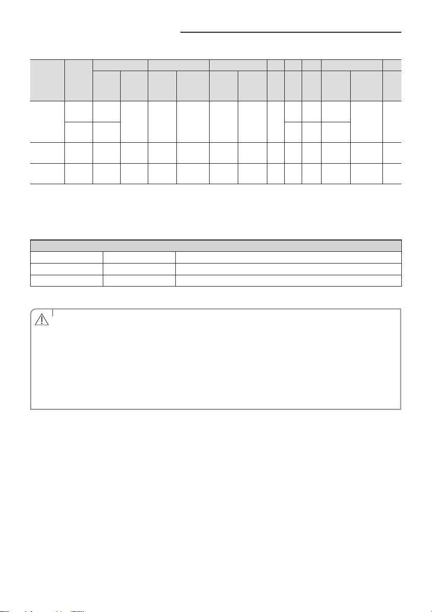
Connect the rated cables only.
Connect using a driver which is able to apply the rated torque to the screws.
If the terminal is loose, re may occur caused by arc. If the terminal is connected too rmly, the terminal may be
damaged.
Tightening Torque (kgf • cm)
M3
M4
M5
5.0~7.5 Communication : F1, F2
12.0~18.0 3phase AC power : 1(L), 2(N), L1(R), L2(S), L3(T), N
20.0~30.0 1phase AC power : 1(L), 2(N), L, N
1N · m = 10 kgf · cm
• When connecting cables, you can connect the cables to the electrical part or connect them through the holes
below depending on the spot.
CAUTION
• Run transmission wiring between the indoor and outdoor units through a conduit to protect against
external forces, and feed the conduit through the wall together with rergerant piping.
• Remove all burrs at the edge of the knock-out hole and secure the cable to the outdoor knock-out using lining
and bushing with an electrical insulation such as rubber and so on.
• Must keep the cable in a protection tube.
• Keep distances of 50mm or more between power cable and communication cable.
• When the cables are connected through the hole, remove the Plate bottom.
Allowance
[mm(inch)]
0(0)
0(0)
0(0)
Min.
[mm
(inch)]
1.8
(0.07)
1.8
(0.07)
2.0
(0.078)
18
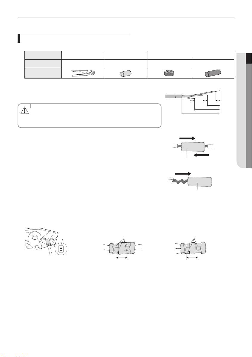
How to connect your extended power cables
1. Prepare the following tools.
Tools Crimping pliers Connection sleeve (mm) Insulation tape Contraction tube (mm)
Spec MH-14 20xØ6.5(HxOD) Width 19mm 70xØ8.0(LxOD)
Shape
ENGLISH
2. As shown in the gure, peel o the shields from the rubber and wire of the
power cable.
- Peel o 20 mm of the wire shields of the tube.
• After peeling o the tube wire, you must insert a contraction tube.
CAUTION
• For information about the power cable specications for indoor and
outdoor units, refer to the installation manual.
Power cable
202020
60
120
180
(Unit: mm)
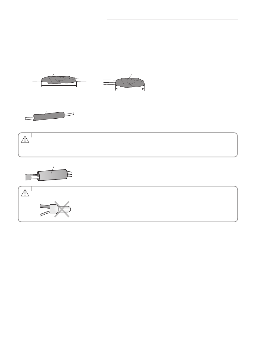
3. Insert both sides of core wire of the power cable into the connection sleeve.
Method 1
Push the core wire into the sleeve from both sides.
Connection sleeve
Method 2
Twist the wire cores together and push it into the sleeve.
Connection sleeve
4. Using a crimping tool, compress the two points and ip it over and compress another two points in the same location.
- The compression dimension should be 8.0.
- After compressing it, pull both sides of the wire to make sure it is rmly pressed.
Compression
dimension
Method 1
Compress it 4 times.
Method 2
Compress it 4 times.
5 mm
5 mm
19
Connecting the cable
5. Wrap it with the insulation tape twice or more and position your contraction tube in the middle of the insulation tape.
A total of three or more layers of insulation is required.
Method 1
Insulation tape
Method 2
Insulation tape
40 mm
6. Apply heat to the contraction tube to contract it.
Contraction tube
7. After tube contraction work is completed, wrap it with the insulation tape to nish.
• Make sure that the connection parts are not exposed to outside.
CAUTION
• Be sure to use insulation tape and a contraction tube made of approved reinforced insulating materials that have
the same level of withstand voltage with the power cable. (Comply with the local regulations on extensions.)
Insulation tape
• In case of extending the electric wire, please DO NOT use a round-shaped Pressing socket.
WARNING
- Incomplete wire connections can cause electric shock or a re.
35 mm
20

Connecting the refrigerant pipe
Refrigerant piping system
Items
AC090FCAEH
AC100FCADH
AC100FCASEH
RC090HXEA
RC100DHXA
RC100SHXEA
Applicable outdoor unit models
Total pipe length (L
+…+Ln+1+a+b) - - 50 m 75 m
1
Main pipe (L
) 50 m 75 m 30 m 50 m
1
Max. distance among indoor units (D) - - 10 m 10 m
Max. length after branch - - 15 m 15 m
Max. height dierence between outdoor and indoor units (h
Max. height dierence among indoor units(h
2
Max Pipe length dierence among indoor units after branch
[L
or L2-L4 or L2-L5 or a-b or (a+L2)-(b+L4) or (a+L3)-(b+L5)]
2-L3
"n" means the number of indoor unit connection of DPM.
n=1
outdoor
n=2
outdoor
L
1
L
1
L
3
L
2
indoor
D
indoor
indoor
h
2
Use a joint kit that is only for DPM.
AC071HCAPKH
AC090HCADH
AC100HCADH
AC120HCADH
AC100JXADH
AC120JXADH
AC100JXADEH1
) 30 m 30 m 30 m 30 m
1
) - - 0.5 m 0.5 m
n=3
h
1
outdoor
n=4
h
1
outdoor
Maximum allowable length
Single installation DPM installation
AC100FCAPH
AC100FCAFH
RC100PHXA
RC100ZHXEA
RC100DHXEH
RC100DHXEG
RC125HX
RC140HX
RC155DHXEH
RC155DHXEG
RC180DHXGH
RC180DHXGG
AC090HCAPKH
AC100HCAPH
AC100FCADH
RC100DHXA
AC100HCADH
AC120HCADH
AC100FCAPH
RC100PHXA
RC125DHXEB
RC125DHXGA
RC125PHXA
RC140DHXEB
RC140DHXGA
RC140PHXA
AC140HCADH
AC120HCAPH
AC140HCAPH
AC140HCADH
AC140JXADH
- - 5 m 5 m
L
2
indoor
4
L
2
indoor
indoor
indoor
D
D
indoor
indoor
D
D
indoor
h
h
L
1
L
3
L
a
L
L
1
3
L
4
b
L
5
ENGLISH
2
h
1
2
h
1
21

Connecting the refrigerant pipe
Temper grade and minimum thickness of the refrigerant pipe
Outer diameter [mm] Minimum thickness [mm] Temper grade
ø6.35 0.7
ø9.52 0.7
ø12.70 0.8
ø15.88 1.0
ø15.88 0.8
ø22.23 0.9
• Make sure to use C1220T-1/2H (Semi-hard) pipe for more than Ø19.05mm. In case of using C1220T-O (Soft) pipe
for Ø19.05mm, pipe may be broken, which can result in an injury.
CAUTION
Make at least one round:
It will reduce noise and vibration
The appearance of the unit may be dierent from the diagram depending on the
model.
• After connecting pipes with knock-out treatment, plug the space.
CAUTION
• Following the pipe connection, make sure to proceed precisely to prevent interference with the internal parts.
C1220T-O
C1220T-1/2H OR C1220T-Hø19.05 0.9
Adding refrigerant (R-410A)
The outdoor unit is loaded with sucient refrigerant for the standard piping. Thus, refrigerant must be added if the piping is
lengthened. This operation can only be performed by a qualied refrigeration specialist. For quantity of adding refrigerant,
refer to page 24.
1. Check that the stop valve is closed entirely.
2. Charge the refrigerant through the service port of liquid stop valve.
• Do not charge the refrigerant through the gas side service port.
NOTE
22

3. If you cannot charge the refrigerant according to the upper steps, following these :
1) Open both liquid stop valve and gas stop valve.
2) Operate the air conditioner by pressing the K2 key on the outdoor unit PCB.
3) About 30 minutes later, charge the refrigerant through the service port of g
as stop valve.
• If necessary, refer to the pressure table classied by outdoor temperature.
NOTE
Outdoor unit
Gas side stop valve(service port)
Liquid side stop valve(service port)
Ref.
Indoor unit
Balance Vacuum pump
1
Important information regulation regarding the refrigerant used
This product contains uorinated greenhouse gases. Do not vent gases into the atmosphere.
• Inform user if system contains 5 tCO₂e or more of uorinated greenhouse gases. In this case, it has to be checked
for leakage at least once every 12 months, according to regulation n°517/2014. This activity has to be covered by
CAUTION
qualied personnel only.
• In case situation above (5 tCO₂e or more of R-410A), installer (or recognized person which has responsibility for
nal check) has to provide a maintenance book, with all the information recorded according to REGULATION
(EU) No 517/2014 OF THE EUROPEAN PARLIAMENT AND OF THE COUNCIL of 16 April 2014 on uorinated
greenhouse gases.
Please ll in the following with indelible ink on the refrigerant charge label
supplied with this product and on this manual.
① : The factory refrigerant charge of the product.
② : The additional refrigerant amount charged in the eld.
① + ② : The total refrigerant charge.
Refrigerant type GWP value
R-410A 2088
GWP=Global Warming Potential
Calculating tCO₂e : kg x GWP / 1000
ENGLISH
a. Factory refrigerant charge of the product: see unit name plate
b. Additional refrigerant amount charged in the eld(Refer to the
NOTE
above information for the quantity of refrigerant replenishment.)
c. Total refrigerant charge
d. Refrigerant cylinder and manifold for charging
The lled-out label must be adhered in the proximity of the product charging
port (e.g. onto the inside of the stop valve cover).
Indoor unit
Unit
①, a
②, b
①+②, C
②
d
①
kg tCOe
23

Adding refrigerant (R-410A)
How to Calculate the Quantity of Adding Refrigerant
The quantity of additional refrigerant is variable according to the installation situation. Thus, make sure the outdoor unit
situation before adding refrigerant. This operation can only be performed by a qualied refrigeration specialist.
Single installation outdoor unit
Model
0~30 30~40 40~50 50~60 60~70 70~75
Interconnection pipe length (m)
AC090FCADEH/AC090FCAPEH/AC100FCADH/
RC090DHXEA/RC090PHXEA/RC100DHXA/AC090HCADH/
AC100HCADH/AC120HCADH/AC100JXADH/
0 +50g/m over 30m - - -
AC120JXADH/AC100JXADEH1
AC071HCAPH 0 +20g/m over 30m - - -
AC100FCAPH/AC100FCAFEH/RC100DHXEG/RC100DHXEH/
RC100PHXA/RC100ZHXEA/RC125HX/RC140HX/
RC155DHXEG/RC155DHXEH/RC180DHXGG/RC180DHXGH/
0 +50g/m over 30m
AC140HCADH/AC090HCAPH/AC100HCAPH/
AC120HCAPH/AC140HCAPH/AC140JXADH
AC090FCASEH/AC100FCASEH/RC090SHXEA/RC100SHXEA + 40 g/m over 5m - - -
DPM installation outdoor unit
Model
AC100FCADH/
RC100DHXA
AC100FCAPH/
RC100PHXA/RC125DHXEB/
RC125DHXGA/RC125PHXA/
RC140DHXEB/RC140DHXGA/
RC140PHXA
AC100HCADH/
AC120HCADH
AC140HCADH Φ 9.52 L
"n" means the number of indoor unit connection of DPM.
Diameter of L1, a
& b pipe
Φ 9.52 L
Φ 9.52 L
Φ 9.52 L
Installation condition Amount of additional refrigerant charging
+a+b-5) x 40 [g] + (L2+...+L
(L
+ ... + L
1
+ ... + L
1
+ ... + L
1
+ ... + L
1
n+1
n+1
n+1
n+1
≤ 50 m
≤ 75m
≤ 50 m
≤ 75m
1
+a+b)< 5 m, (L2+...+L
If (L
1
+a+b-5) x 40[g] + (L2+...+L
(L
1
+a+b)< 5 m, (L2+...+L
If (L
1
+a+b-5) x 35 [g] + (L2+...+L
(L
1
+a+b)< 5m, (L2+...+L
If (L
1
+a+b-5) x 35 [g] + (L2+...+L
(L
1
+a+b)< 5m, (L2+...+L
If (L
1
n+1
) x 30 [g]
n+1
n+1
) x 30 [g]
n+1
n+1
) x 20 [g]
n+1
n+1
) x 20 [g]
n+1
) x 30 [g]
) x 30 [g]
) x 20 [g]
) x 20 [g]
24

Installing DPM
DPM allowable Outdoor and indoor unit models
DPM allowable Outdoor and indoor unit models
Outdoor unit models
AC100FCADH
AC100FCAPH
RC125DHXA
RC125PHXA
RC140DHX
RC140PHXA
AC100HCADH AC052HBMDKH AC035HBMDKH N/A
AC120HCADH AC060HBMDKH AC035HBMDKH N/A
AC140HCADH AC071HBMDKH AC052HBMDKH AC035HBMDKH
2 indoor units connection 3 indoor units connection 4 indoors unit connection
Indoor unit Indoor unit Indoor unit
AC052FBNDEH/AC052FB4DEH AC035FBNDEH N/A
AC052FBNDEH/AC052FB4DEH AC035FBNDEH N/A
AC060FBNDEH AC052FBNDEH/AC052FB4DEH N/A
AC060FBNDEH AC052FBNDEH/AC052FB4DEH N/A
AC071FBNDEH/AC071FB4DEH AC052FBNDEH AC035FBNDEH
AC071FBNDEH/AC071FB4DEH AC052FBNDEH
AC035FBNDEH
Installation of multiple indoor units should consist of units that have the same capacity.
e.g. When you install the RC140DHXEA outdoor unit as DPM combination such as 2 indoor units connection, only the
combination of two ACN071NDEHA OR two NS0714DXEA is available.
Space requirements for indoor and outdoor units and piping installation
(Refer to page 7~8 installation specication.)
Two indoor units should be installed in one area which is not divided by a wall.
The distance between two indoor units should be within a straight-line of 10m.
After branching, the distance between the piping connected to the two indoor units should be within 1m.
The height dierence between two units should be within 0.5m.
Use the joint KIT that is only for DPM. (Please refer to the table below)
DPM KIT
2-Indoor units connection 3-Indoor units connection 4-Indoor units connection
MXJ-2D2509K MXJ-3D2509K MXJ-4D2509K
ENGLISH
Connecting communication line and wired remote controller
In case of 2 indoor units connection
Outdoor
unit
F1/F2
L/N
F1/F2 F1/F2
Indoor unit #1
L/N L/N
Indoor unit #2
Remote control
In case of 3indoor units connection
Outdoor
unit
F1/F2
L/N
F1/F2 F1/F2F1/F2 F1/F2
Indoor unit #1
L/N L/NL/N L/N
Indoor unit #2 Indoor unit #3
Remote control
25

Installing DPM
In case of 4indoor units connection
F1/F2
Outdoor
unit
L/N
The wired remote controller can be used with any of the DPM indoor units.
F1/F2 F1/F2 F1/F2F1/F2 F1/F2 F1/F2
Indoor unit #1
L/N L/N L/NL/N L/N L/N
Indoor unit #2 Indoor unit #3 Indoor unit #4
Remote control
Operation and specication
The two, the three, or the four sets of the indoor units with DPM installation which are controlled by wired and wireless
remote controller work equally. (All controls such as ON/OFF, cooling/heating/dehumidication/ventilation, high/
medium/low wind, xing louver angle/swing are equally applied.)
Thermo OFF which stops when indoor temperature reaches set temperature works by the average sensor value of the
indoor temperature of the all indoor units.
When one of the several indoor units has a problem, they protect operation or stop working.
Instruction for installation and operation
You should install the DPM according to the above installation specication and eliminate the factors that give electrical
load to the both indoor units when installing and operating. (Heater / window / front door / ventilation / partition that
divides space)
You should provide sucient instructions about the operation method and specication features to users and ll in caution
phrases on wired remote controller when necessary.
- <The air-conditioners in this area are special type to be controlled simultaneously.>
Set up indoor quantity by key switch(K1, K2)
Press and hold K1 switch to enter the setting mode on the number of the installed indoor unit : Check “A0” sign on
7-segment
- Press K2 switch to set the number of the installed indoor unit :
Ex) If there are two indoor units, press K2 switch twice, and check "A2" sign on 7-segment.
If there are three indoor units, press K3 switch three times, and check "A3" sign on 7-segment.
If there are four indoor units, press K4 switch four times, and check "A4" sign on 7-segment.
- Press K1 switch to complete setting the number of the installed indoor unit : Check "AA" sign on 7-segment.
Connecting up and removing air in the circuit
• When installing, make sure there is no leakage. When recovering the refrigerant, ground the compressor rst
before removing the connection pipe. If the refrigerant pipe is not properly connected and the compressor
CAUTION
works with the service valve open, the pipe inhales the air and it makes the pressure inside of the refrigerant
cycle abnormally high. It may cause explosion and injury.
The air in the indoor unit and in the pipe must be purged. If air remains in the refrigeration pipes, it will aect the compressor
either reduce cooling/heating capacity or lead to a malfuction. Refrigerant for air purging is not charged in the outdoor unit.
Use Vacuum Pump as shown at the right gure.
1. Connect each assembly pipe to the appropriate valve on the outdoor unit and tighten the are nut.
26

2. Referring to the illustration opposite, tighten the are nut on section B rst
manually and then with a torque wrench, applying the following torque.
Outer Diameter (D) Torque (N•m)
ø6.35 mm(1/4") 14~18
ø9.52 mm(3/8") 34~42
ø12.70 mm(1/2") 49~61
ø15.88 mm(5/8") 68~82
ø19.05 mm(3/4") 100~120
Outdoor unit
A (Gas) C
B (Liquid)
3. Connect the charging hose of low pressure side of manifold gauge to the
packed valve having a service port as shown at the gure.
• Make the electrical connection and leave the system into “stand by
mode”. Do not turn on the system.
CAUTION
• This is necessary to speed up vacuum operation (full OPEN
position of Electronic Expansion Valve - EEV -).
4. Open the valve of the low pressure side(A) of manifold gauge
counterclockwise.
Vacuum
pump
The designs and shape are subject to
change according to the model.
5. Purge the air from the system using vacuum pump for about 10minutes.
Close the valve of the low pressure side of manifold gauge clockwise.
Make sure that pressure gauge shows -0.1MPa(-76cmHg) after about
10minutes. This procedure is very important to avoid a gas leak.
Turn o the vacuum pump.
B(liquid) A(gas)
Remove the hose of the low pressure side of manifold gauge.
6. Set valve cork of both liquid side and gas side of packed valve to the open
position.
7. Mount the valve stem nuts and the service port cap to the valve, and tighten
thematthetorqueof183kgf•cmwithatorquewrench.
8. Check for gas leakage.
At this time, especially check for gas leakage from the 3-way valve’s stem nuts(A port), and from the service port cap.
D
ENGLISH
• Connect the indoor and outdoor units using pipes with ared connections (not supplied). For the lines, use
insulated, unwelded, degreased and deoxidized copper pipe, (Cu DHP type to ISO 1337 or UNI EN 12735-1),
CAUTION
suitable for operating pressures of at least 4200kPa and for a burst pressure of at least 20700kPa. Copper pipe
for hydro-sanitary applications is completely unsuitable.
• For sizing and limits (height dierence, line length, max. bends, refrigerant charge, etc.) see “Connecting
refrigerant pipe section”.
27

Cutting/Flaring the pipes
1. Make sure that you have the required tools available. (pipe cutter, reamer, aring tool and pipe holder)
2. If you wish to shorten the pipes, cut it with a pipe cutter, taking care to ensure that the cut edge remains at a 90° angle
with the side of the pipe. Refer to the illustrations below for examples of edges cut correctly and incorrectly.
Oblique Rough Burr
3. To prevent any gas from leaking out, remove all burrs at the cut edge of the pipe, using a reamer.
4. Slide a are nut on to the pipe and modify the are.
Outer Diameter (D) Depth (A)
ø6.35 mm(1/4") 1.3 mm
ø9.52 mm(3/8") 1.8 mm
ø12.70 mm(1/2") 2.0 mm
ø15.88 mm(5/8") 2.2 mm
ø19.05 mm(3/4") 2.2 mm
5. Check that the aring is correct, referring to the illustrations below for examples of incorrect aring.
InclinedCorrect
Surface
CrackedDamaged
Uneven
Thickness
6. Align the pipes and tighten the are nuts rst manually and then with a torque wrench, applying the following torque.
Valve
1/4" 17 18 23 20 18 16~18 Allen(hex.) 5 9 - 0.34
3/8" 22 42 23 20 18 16~18 Allen(hex.) 5 9 - 0.34
1/2" 26 55 29 40 18 16~18 Allen(hex.) 5 13 - 0.34
5/8" 29 65 29 40 18 16~18 Allen(hex.) 5 13 - 0.34
3/4" 36 100 38 40 18 16~18 Allen(hex.) 5 13 - 0.34
Flare nut Valve cap Pressure port cap Valve needle Pressure port
Wrench(mm) N•m Wrench(mm) N•m Wrench(mm) N•m Wrench(mm) N•m Wrench(mm) N•m
1 N·m = 10 kgf·cm
• If the pipes require brazing ensure that OFN(Oxygen Free Nitrogen) is owing through the system.
CAUTION
• Nitrogen blowing pressure range is 0.02 ~ 0.05MPa.
28

Performing leak tests
LEAK TEST WITH NITROGEN (before opening valves)
In order to detect basic refrigerant leaks, before recreating the vacuum and
recirculating the R-410A, it’s responsable of installer to pressurize the whole
system with nitrogen (using a cylinder with pressure reducer) at a pressure
above 40 bar (gauge).
LEAK TEST WITH R-410A (after opening valves)
Before opening valves, discharge all the nitrogen into the system and create
vacuum. After opening valves check leaks using a leak detector for refrigerant
R-410A.
Once you have completed all the connections, check for possible leaks using
leak detector specically designed for HFC refrigerants.
To check for gas leaks on the Outdoor
unit
Then, using a leak detector, check the
Valves on sections A and B.
B(Liquid)
The designs and shape are subject to
change according to the model.
A(Gas)
Connecting the drain hose to the outdoor unit
When using the air conditioner in the heating mode, ice may accumulate . During de-icing (defrost operation), the
condensed water must be drained o safely. Consequently, you must install a drain hose on the outdoor unit, following the
instructions below.
1. Make space more than 80 mm between the bottom of the outdoor unit and the ground for installation of the drain hose,
as shown in gure.
2. Insert the drain plug into the hole on the underside of the outdoor unit.
3. Connect the drain hose to the drain plug.
4. Ensure that the drained water runs o correctly and safely.
ENGLISH
‘B’mm
80 mm
5. Be sure to plug the rest of drain holes not connected with drain plugs using drain caps.
DRAIN CAP(5EA)
DRAIN PLUG(2EA)
When installing the product, make sure that the rack is not placed under the drain hole.
If the product is installed in a region of heavy snow, allow enough separation distance between the product and the
ground.
13mm
29

Refrigerant pipe work
Insulating the pipes
Once you have checked that there are no leaks in the system, you can insulate the piping and hose.
1. To avoid condensation problems, place an insulator around each refrigerant
pipe.
• When insulate the pipe, be sure to overlap the insulation.
• The insulation has to be produced in full compliance of European
NOTE
regulation reg. EEC / EU 2037/ 2000 that requires the use of
sheaths insulation form without using CFC and HCFC gases for
health and the environment.
• When insulating the pipe, use non-slit insulator.
CAUTION
2. Select the insulation of the refrigerant pipe.
Insulate the gas side and liquid side pipe referring to the thickness according to the pipe size.
Less than Indoor temperature of 30°C and humidity of 85% is the standard condition. If installing in a high humidity
condition, use one grade thicker insulator by referring to the table below. If installing in an unfavorable conditions, use
thicker one.
Insulator’s heat-resistance temperature should be more than 120°C.
Insulation Type (Heating/Cooling)
Pipe Pipe size
Liquid pipe
Gas pipe
Ø6.35~Ø9.52 9t 9t
Ø12.7~Ø19.05 13t 13t
Ø9.52~Ø19.05 19t 25t
Standard
[Less than 30°C, 85%]
EPDM, NBR
Ø6.35 13t 19t
High humidity
[over 30°C, 85%]
NBR
Remarks
Internal temperature is
higher than 120°C
When installing insulation in places and conditions below, use the same insulation that is used for high humidity
conditions.
<Geological condition>
- High humidity places such as shoreline, hot spring, near lake or river, and ridge (when the par t of the building is
covered by earth and sand.)
<Operation purpose condition>
- Restaurant ceiling, sauna, swimming pool etc.
<Building construction condition>
- The ceiling frequently exposed to moisture and cooling is not covered.
e.g. The pipe installed at a corridor of a dormitory and studio or near an exit that opens and closes frequently.
- The place where the pipe is installed is highly humid due to the lack of ventilation system.
30

Installing an oil trap
Check the following list and install an oil trap.
Install an oil trap only when the outdoor unit is at a higher level than the indoor unit.
Based on cooling operation, install it on the gas side pipe only.
Install the oil trap only in between the outdoor unit and the rst branch joint and it should be installed at every 10 m.
Radius of curvature (R) on the oil trap are as follows;
Pipe diameter (D) 12.70 15.88 19.05 22.23 25.40 28.60 31.75
Radius of curvature (R) 25 and over 32 and over 38 and over 41 and over 51 and over 57 and over 60 and over
Height of the oil trap (H): 4R ≤ H ≤ 6R
ENGLISH
When the indoor unit is installed at a higher
place than the outdoor unit
Indoor unit
Outdoor unit
Oil trap
(Install it at every 10 m)
When the outdoor unit is installed at a higher
place than indoor unit
Outdoor unit
Oil trap (Install it at
every 10 m)
Cut on insulation
Insulation
Indoor unit
Oil trap (Gas side pipe)
• If the compressor operates in the condition that the refrigerant pipe is not installed correctly and the service
valve is opened, the refrigerant pipe may intake air and the pressure inside the refrigerant cycle will increase,
CAUTION
which may result in explosion and injury.
• Make a hole (10 mm in diameter) on the insulation so that rain water can be drained in case it gets inside of the
insulation. However, be careful not to damage the pipe.
31

Using stop valve
To Open the Stop Valve
1. Open the cap and turn the stop valve counterclockwise by using a hexagonal
wrench.
2. Turn it until the axis is stopped.
• Do not apply excessive force to the stop valve and always use
special instruments. Otherwise, the stopping box can be damaged
NOTE
and the back sheet can leaks.
• If the watertight sheet leaks, turn the axis back by half, tighten the
stopping box, then check the leakage again. If there is no leakage
any more, tighten the axis entirely.
3. Tighten the cap securely.
To Close the Stop Valve
1. Remove the cap.
2. Turn the stop valve clockwise by using a hexagonal wrench.
3. Tighten the axis until the valve reached the sealing point.
4. Tighten the cap securely.
• When you use the service port, always use a charging hose, too.
• Check the leakage of refrigerant gas after tightening the cap.
CAUTION
• Must use a spanner and wrench when you open/tighten the stop valve.
Service port
Cap
Axis
Sealing point
32

Interface module Installation (Optional)
Accessories (Interface module : MIM-B13D)
Interface module
1. Fix the case at with bolts on the side of the control box in the outdoor unit.
(See the picture)
2. Attach the Interface module PCB to the case in the control box in the
outdoor unit, then connect the power and the communication cable
between the Interface module and the outdoor unit; refer to the gure of
pages 14~15.
3. If you install a Interface module to an outdoor unit, every indoor unit which
is connected to an outdoor unit can be controlled simultaneously.
4. Each outdoor unit connected to the same centralized controller has its own
Interface module.
Interface module
power cable
Interface module
communication cable
Installation Manual Case Cable-tie
Fix the case with hinges
(Control Box in the outdoor unit)
ENGLISH
(Control Box in the outdoor unit-ACHCAH, ACJXAH, AC100JXADEH1)
Fix the case
33

Pump down Procedure
Pump down will be carried out when an evaporator is replaced or when the unit is relocated in another area.
1. Remove the cap from the low pressure side.
2. Turn the low pressure side valve clockwise to close and connect a pressure
gauge (low pressure side) to the service valve, and open the valve again.
3. Set the unit to the cooling Test mode by pushing K2 button (Check if the
compressor is operating.)
4. Turn the high pressure side valve clockwise to close.
5. When the pressure gauge indicates “0” turn the low pressure side valve
clockwise to close.
6. Stop operation of the air conditioner by pushing K3 button.
7. Close the each cap of valve.
Relocation of the air conditioner
• Refer to this procedure when the unit is relocated.
NOTE
• Carry out the pump down procedure (refer to the details of ‘pump down’).
• Remove the power cord.
• Disconnect the assembly cable from the indoor and outdoor units.
• Remove the are nut connecting the indoor unit and the pipe.
• At this time, cover the pipe of the indoor unit and the other pipe using a cap or vinyl plug to avoid foreign
material entering.
• Disconnect the pipe connected to the outdoor unit. At this time, cover the valve of the outdoor unit and the
other pipe using a cap or vinyl plug to avoid foreign material entering.
• Make sure you do not bend the connection pipes in the middle and store together with the cables.
• Move the indoor and outdoor units to a new location.
• Remove the mounting plate for the indoor unit and move it to a new location.
B(liquid) A(gas)
34

Checking correct grounding
If the power distribution circuit does not have a grounding or the grounding does not comply with specications, an
grounding electrode must be installed. The corresponding accessories are not supplied with the air conditioner.
1. Select an grounding electrode that complies with the specications given in
the illustration.
2. Connect the exible hose to the exible hose port.
In damp hard soil rather than loose sandy or gravel soil that has a higher
grounding resistance.
Away from underground structures or facilities, such as gas pipes, water
pipes, telephone lines and underground cables.
At least two metres away from a lightening conductor grounding electrode
and its cable.
• The grounding wire for the telephone line cannot be used to
ground the air conditioner.
NOTE
3. Finish wrapping insulating tape around the rest of the pipes leading to the
outdoor unit.
4. Install a green/yellow coloured grounding wire :
If the grounding wire is too short, connect an extension lead, in a mechanical way and wrapping it with insulating tape
(do not bury the connection).
Secure the grounding wire in position with staples.
• If the grounding electrode is installed in an area of heavy trac, its wire must be connected securely.
NOTE
Carbon
plastic
PVC-insulated green/
yellow wire
30cm
Steel core
Terminal M4
To grounding
50cm
ENGLISH
screw
5. Carefully check the installation, by measuring the grounding resistance with a ground resistance tester. If the resistance is
above required level, drive the electrode deeper into the ground or increase the number of grounding electrodes.
6. Connect the grounding wire to the electrical component box inside of the outdoor unit.
35

Testing operations
1. Check the power supply between the outdoor unit and the auxiliary circuit breaker.
1 phase power supply : L, N
3 phases power supply : R,S,T,N
2. Check the indoor unit.
1) Check that you have connected the power and communication cables correctly. (If the power cable and
communication cables one mixed up or connected incorrectly, the PCB will be damaged.)
2) Check the thermistor sensor, drain pump/hose, and display are connected correctly.
3. Press K1 or K2 on the outdoor unit PCB to run the test mode and stop.
Press K1 button Start Heating test mode Press K1 button Stop Heating test mode 7-seg display :
Press K2 button Start Cooling test mode Press K2 button Stop Cooling test mode 7-seg display :
Press K1 button twice Start Defrost test mode Press K1 button Stop Defrost test mode 7-seg display :
Press K2 button twice StartInverter Checkermode Press K2 button Stop Inverter Checkermode 7-seg display :
(For a service only (ACHCAH, ACJXAH, AC100JXADEH1))
Condition 1 : The outdoor temperature is under 10°C
Condition 2 : All the temperature conditions should meet the defrost conditions
(Except ACHCAH, ACJXAH, AC100JXADEH1)
Outdoor unit
(Only ACHCAH, ACJXAH, AC100JXADEH1)
ON
1 2 3 4
4. After 12 minutes of stationary condition check each indoor unit air treatment :
Cooling mode(indoor unit check) Inlet air temp. - Outlet air temp. : From 10°C to 12°C
Heating mode(indoor unit check) Outlet air temp. - Inlet air temp. : From 11°C to 14°C
In heating mode, the indoor fan motor can remain o to avoid cold air blown into conditioned space.
5. How to reset the power supply of the outdoor unit and deactivate the eco mode (standby mode) :
Outdoor unit type A, B, and C :
Press [K3] button over 1 sec to reset the power supply of the outdoor unit and deactivate the eco mode (standby
mode) Only for AC090FCA, AC100FCA, RC090, RC100, RC125, RC140,
ACHCAH, ACJXAH, AC100JXADEH1 series model.
Outdoor unit
ON
1 2 3 4ON1 2 3 4
36

6. Vie
w Mode : W
Short
push
1 Order frequency 1 Hundreds' digit Tens' digit Unit digit Hz
2 Current frequency 2 Hundreds' digit Tens' digit Unit digit Hz
3 The number of current indoor units 3 Hundreds' digit Tens' digit Unit digit EA
4 The sensor for outdoor air intake 4 + / - Tens' digit Unit digit °C
5 Discharge sensor 5 Hundreds' digit Tens' digit Unit digit °C
6 Eva-Mid sensor 6 + / - Tens' digit Unit digit °C
7 Cond sensor 7 + / - Tens' digit Unit digit °C
8 Current 8 Tens' digit Unit digit
9 Fan RPM 9
10 Target discharge temperature A Hundreds' digit Tens' digit Unit digit °C
11 EEV B Hundreds' digit Tens' digit Unit digit step
12 The capacity sum of indoor units C Tens' digit Unit digit
13 Protective control D
14
15 S/W check F - - - -
hen the K4 switch is pressed, you can see information about our system state as below.
Display contents SEG1 SEG2 SEG3 SEG4 Unit
The rst place of
decimals
The rst place of
decimals
Frequency status
0: Normal
1: Hold
2: Down
3: Up_limit
4: Down_limit
The temperature of heat radiating
plate
Thousands'
digit
0: Cooling
1: Heating
E Hundreds' digit Tens' digit Unit digit -
Hundreds' digit Tens' digit rpm
Protective control
0: No Protective control
1: Freezing
2: Non-stop defrosting
3: Over-load
4: Discharge
5: Total elec tric current
ENGLISH
A
kW
-
Long push 1 Main micom version Year (Hex) Month (Hex) Date ( Tens' digit) Date (Unit digit)
After short push 1 Inverter micom version Year (Hex) Month (Hex) Date (Tens' digit) Date (Unit digit)
After short push 1 E2P version Year (Hex) Month (Hex) Date ( Tens' digit) Date (Unit digit)
Long push K4(Main micom ver.) shor t push 1 more(Inv. micom ver.) short push 1 more(E2P. ver.)
37

Testing operations
7. DIP switch option
ON
1 2 3 4
SW507
DIP switch(SW507) option
Switch 1 Auto address Manual address
Switch 2 Disable snow prevention control Enable snow prevention control
Switch 3
Switch 4
When snow prevention mode is in use, eco mode(standby mode)will not be functional.
When DPM installation is applied, the time for auto addressing will take 1~2minutes.
During the addressing,
for 3 indoor unit connection, , , and for 4 indoor unit connection.
When addressing is completed,
connection,
and for 4 indoor unit connection.
DIP switch(SW508) option
Switch 1 Auto Silence Mode Manual Silence Mode
Switch 2 - Switch 3 - Switch 4 - -
8. Silence Mode DIP switch option
(ACHCAPKH, ACHCAPNH, ACHCADKH, ACHCADNH, ACJXADEH, ACJXADGH,
AC100JXADEH1)
DIP switch(SW507) option
Switch 3 Switch 4 Operation
On On Disable Silence mode
On O Silence mode 1st step
O On Silence mode 2nd step
O O Silence mode 3rd step
ON
1 2 3 4
SW508
On (default) O
Silence Mode option
and will be repeatedly displayed in order for 2 indoor unit connection, , and
, , , and will be repeatedly displayed in order for 2 indoor unit
, , , , and for 3 indoor unit connection, , , , , ,
On(default) O
38

COMMISSION DELEGATED REGULATION (EU) No 626/2011
i)
PRODUCT FICHE (ENERGY LABELLING OF AIR CONDITIONERS)
A Supplier's name -
B
C
D
E
F
G
H
I
J
K
L
M
N
O
P
Q
R
S
T
U
V
Model name
(Indoor/Outdoor)
Sound Power Level
(Indoor/Outdoor)
Refrigerant name
1)
GWP
SEER
Energy eciency class (SEER)
2)
Q
(cooling season)
CE
Pdesignc
SCOP
Energy eciency class (SCOP)
3)
Q
(heating season)
HE
Other heating seasons suitable
for use
Pdesignh (Average)
Back up heating
capacity(Average)
Declared capacity(Average)
Pdesignh (Warmer)
Back up heating
capacity(Warmer)
Declared capacity(Warmer)
Pdesignh (Colder)
Back up heating
capacity(Colder)
Declared capacity(Colder)
dB(A) 57/68 58/69 58/68
kWh/a
kWh/a
Samsung Electronics
Co., Ltd.
-
AC090FB4DEH/
AC090FCADEH
- R-410A R-410A R-410A
- 2088 2088 2088
5.6 5.6 5.6
- A+ A+ A+
iii)
563 625 625
kW 9.0 10.0 10.0
- 3.8 3.8 3.8
- A A A
iii)
2432 2800 2800
- -
kW 6.6 7.6 7.6
kW 0 0 0
kW 6.6 7.6 7.6
kW - - -
kW - - -
kW - - kW - - -
kW - - -
kW - - -
Samsung Electronics
Co., Ltd.
AC100FB4DEH/
AC100FCADEH
ii)
Samsung Electronics
Co., Ltd.
ENGLISH
AC100FB4DEH/
AC100FCADGH
iv)
1. Refrigerant leakage contributes to climate change. Refrigerant with lower global warming potential (GWP) would
contribute less to global warming than a refrigerant with higher GWP, if leaked to the atmosphere.
This appliance contains a refrigerant uid with a GWP equal to [2088]. This means that if 1 kg of this refrigerant uid
would be leaked to the atmosphere, the impact on global warming would be [2088] times higher than 1kg of CO2 , over
a period of 100 years.
Never try to interfere with the refrigerant circuit yourself or disassemble the product yourself and always ask a
professional.
2. Energy consumption “XYZ” kWh per year, based on standard test results. Actual energy consumption will depend on how
the appliance is used and where it is located.
3. Energy consumption “XYZ” kWh per year, based on standard test results. Actual energy consumption will depend on how
the appliance is used and where it is located.
39

COMMISSION DELEGATED REGULATION (EU) No 626/2011
i)
PRODUCT FICHE (ENERGY LABELLING OF AIR CONDITIONERS)
A Supplier's name -
B
C
D
E
F
G
H
I
J
K
L
M
N
O
P
Q
R
S
T
U
V
Model name
(Indoor/Outdoor)
Sound Power Level
(Indoor/Outdoor)
Refrigerant name
1)
GWP
SEER
Energy eciency class (SEER)
2)
Q
(cooling season)
CE
Pdesignc
SCOP
Energy eciency class (SCOP)
3)
Q
(heating season)
HE
Other heating seasons suitable
for use
Pdesignh (Average)
Back up heating
capacity(Average)
Declared capacity(Average)
Pdesignh (Warmer)
Back up heating
capacity(Warmer)
Declared capacity(Warmer)
Pdesignh (Colder)
Back up heating
capacity(Colder)
Declared capacity(Colder)
dB(A) 58/67 59/66 59/66
kWh/a
kWh/a
Samsung Electronics
Co., Ltd.
-
AC090FB4PEH/
AC090FCAPEH
- R-410A R-410A R-410A
- 2088 2088 2088
6.4 6.4 6.4
- A++ A++ A++
iii)
492 547 547
kW 9.0 10.0 10.0
- 4.2 4.2 4.2
- A+ A+ A+
iii)
2533 3100 3100
- -
kW 7.6 9.3 9.3
kW 0 0 0
kW 7.6 9.3 9.3
kW - - -
kW - - -
kW - - kW - - -
kW - - -
kW - - -
Samsung Electronics
AC100FB4PEH/
AC100FCAPEH
ii)
Co., Ltd.
iv)
Samsung Electronics
Co., Ltd.
AC100FB4PEH/
AC100FCAPGH
1. Refrigerant leakage contributes to climate change. Refrigerant with lower global warming potential (GWP) would
contribute less to global warming than a refrigerant with higher GWP, if leaked to the atmosphere.
This appliance contains a refrigerant uid with a GWP equal to [2088]. This means that if 1 kg of this refrigerant uid
would be leaked to the atmosphere, the impact on global warming would be [2088] times higher than 1kg of CO2 , over
a period of 100 years.
Never try to interfere with the refrigerant circuit yourself or disassemble the product yourself and always ask a
professional.
2. Energy consumption “XYZ” kWh per year, based on standard test results. Actual energy consumption will depend on how
the appliance is used and where it is located.
3. Energy consumption “XYZ” kWh per year, based on standard test results. Actual energy consumption will depend on how
the appliance is used and where it is located.
40

PRODUCT FICHE (ENERGY LABELLING OF AIR CONDITIONERS)
ii)
A Supplier's name -
B
C
D
E
F
G
H
I
J
K
L
M
N
O
P
Q
R
S
T
U
V
Model name
(Indoor/Outdoor)
Sound Power Level
(Indoor/Outdoor)
Refrigerant name
1)
GWP
SEER
Energy eciency class (SEER)
2)
Q
(cooling season)
CE
iii)
Pdesignc
SCOP
Energy eciency class (SCOP)
3)
Q
(heating season)
HE
iii)
Other heating seasons suitable
for use
Pdesignh (Average)
Back up heating
capacity(Average)
Declared capacity(Average)
Pdesignh (Warmer)
Back up heating
capacity(Warmer)
Declared capacity(Warmer)
Pdesignh (Colder)
Back up heating
capacity(Colder)
Declared capacity(Colder)
dB(A) 60/68 65/68 65/69
kWh/a
kWh/a
-
Samsung
Electronics Co., Ltd.
AC100FB4FEH/
AC100FCAFEH
Samsung
Electronics Co., Ltd.
AC090FBMSEH/
AC090FCASEH
Samsung
Electronics Co., Ltd.
AC100FBMSEH
AC100FCASEH
- R-410A R-410A R-410A
- 2088 2088 2088
6.7 4.3 4.3
- A++ C C
iii)
522 733 814
kW 10.0 9.0 10.0
- 4.3 3.4 3.4
- A+ A A
iii)
- -
3419 2800 2800
iv)
kW 10.5 6.8 6.8
kW 0 0 0
kW 10.5 6.8 6.8
kW - - -
kW - - -
kW - - kW - - -
kW - - -
kW - - -
ENGLISH
1. Refrigerant leakage contributes to climate change. Refrigerant with lower global warming potential (GWP) would
contribute less to global warming than a refrigerant with higher GWP, if leaked to the atmosphere.
This appliance contains a refrigerant uid with a GWP equal to [2088]. This means that if 1 kg of this refrigerant uid
would be leaked to the atmosphere, the impact on global warming would be [2088] times higher than 1kg of CO2 , over
a period of 100 years.
Never try to interfere with the refrigerant circuit yourself or disassemble the product yourself and always ask a
professional.
2. Energy consumption “XYZ” kWh per year, based on standard test results. Actual energy consumption will depend on how
the appliance is used and where it is located.
3. Energy consumption “XYZ” kWh per year, based on standard test results. Actual energy consumption will depend on how
the appliance is used and where it is located.
41

COMMISSION DELEGATED REGULATION (EU) No 626/2011
i)
PRODUCT FICHE (ENERGY LABELLING OF AIR CONDITIONERS)
A Supplier's name -
B
C
D
E
F
G
H
I
J
K
L
M
N
O
P
Q
R
S
T
U
V
Model name
(Indoor/Outdoor)
Sound Power Level
(Indoor/Outdoor)
Refrigerant name
1)
GWP
SEER
Energy eciency class (SEER)
2)
Q
(cooling season)
CE
Pdesignc
SCOP
Energy eciency class (SCOP)
3)
Q
(heating season)
HE
Other heating seasons suitable
for use
Pdesignh (Average)
Back up heating
capacity(Average)
Declared capacity(Average)
Pdesignh (Warmer)
Back up heating
capacity(Warmer)
Declared capacity(Warmer)
Pdesignh (Colder)
Back up heating
capacity(Colder)
Declared capacity(Colder)
dB(A) 65/67 65/68 65/68
kWh/a
kWh/a
Samsung Electronics
Co., Ltd.
-
AC090FBMDEH/
AC090FCADEH
- R-410A R-410A R-410A
- 2088 2088 2088
5.4 5.2 5.1
- A A A
iii)
583 673 686
kW 9.0 10.0 10.0
- 3.7 3.7 3.5
- A A A
iii)
2573 2573 2720
-
kW 6.8 6.8 6.8
kW 0 0 0
kW 6.8 6.8 6.8
kW - - -
kW - - -
kW - - kW - - -
kW - - -
kW - - -
Samsung Electronics
AC100FBMDEH/
AC100FCADEH
ii)
Co., Ltd.
iv)
-
Samsung Electronics
Co., Ltd.
AC100FBMDEH/
AC100FCADGH
1. Refrigerant leakage contributes to climate change. Refrigerant with lower global warming potential (GWP) would
contribute less to global warming than a refrigerant with higher GWP, if leaked to the atmosphere.
This appliance contains a refrigerant uid with a GWP equal to [2088]. This means that if 1 kg of this refrigerant uid
would be leaked to the atmosphere, the impact on global warming would be [2088] times higher than 1kg of CO2 , over
a period of 100 years.
Never try to interfere with the refrigerant circuit yourself or disassemble the product yourself and always ask a
professional.
2. Energy consumption “XYZ” kWh per year, based on standard test results. Actual energy consumption will depend on how
the appliance is used and where it is located.
3. Energy consumption “XYZ” kWh per year, based on standard test results. Actual energy consumption will depend on how
the appliance is used and where it is located.
42

PRODUCT FICHE (ENERGY LABELLING OF AIR CONDITIONERS)
ii)
A Supplier's name -
B
C
D
E
F
G
H
I
J
K
L
M
N
O
P
Q
R
S
T
U
V
Model name
(Indoor/Outdoor)
Sound Power Level
(Indoor/Outdoor)
Refrigerant name
1)
GWP
SEER
Energy eciency class (SEER)
2)
Q
(cooling season)
CE
Pdesignc
SCOP
Energy eciency class (SCOP)
3)
Q
(heating season)
HE
Other heating seasons suitable
for use
Pdesignh (Average)
Back up heating
capacity(Average)
Declared capacity(Average)
Pdesignh (Warmer)
Back up heating
capacity(Warmer)
Declared capacity(Warmer)
Pdesignh (Colder)
Back up heating
capacity(Colder)
Declared capacity(Colder)
dB(A) 61/68 61/68 61/69
kWh/a
kWh/a
-
Samsung
Electronics Co., Ltd.
AC090HBMDKH/
AC090HCADKH
Samsung
Electronics Co., Ltd.
AC090HBMDKH/
AC090HCADNH
Samsung
Electronics Co., Ltd.
AC100HBMDKH/
AC100HCADKH
- R-410A R-410A R-410A
- 2088 2088 2088
5.7 5.7 5.6
- A+ A+ A+
iii)
553 553 625
kW 9.0 9.0 10.0
- 4.0 4.0 4.0
- A+ A+ A+
iii)
- -
2380 2380 2380
iv)
kW 6.8 6.8 6.8
kW 0 0 0
kW 6.8 6.8 6.8
kW - - -
kW - - -
kW - - kW - - -
kW - - -
kW - - -
ENGLISH
1. Refrigerant leakage contributes to climate change. Refrigerant with lower global warming potential (GWP) would
contribute less to global warming than a refrigerant with higher GWP, if leaked to the atmosphere.
This appliance contains a refrigerant uid with a GWP equal to [2088]. This means that if 1 kg of this refrigerant uid
would be leaked to the atmosphere, the impact on global warming would be [2088] times higher than 1kg of CO2 , over
a period of 100 years.
Never try to interfere with the refrigerant circuit yourself or disassemble the product yourself and always ask a
professional.
2. Energy consumption “XYZ” kWh per year, based on standard test results. Actual energy consumption will depend on how
the appliance is used and where it is located.
3. Energy consumption “XYZ” kWh per year, based on standard test results. Actual energy consumption will depend on how
the appliance is used and where it is located.
43

COMMISSION DELEGATED REGULATION (EU) No 626/2011
i)
PRODUCT FICHE (ENERGY LABELLING OF AIR CONDITIONERS)
A Supplier's name -
B
C
D
E
F
G
H
I
J
K
L
M
N
O
P
Q
R
S
T
U
V
Model name
(Indoor/Outdoor)
Sound Power Level
(Indoor/Outdoor)
Refrigerant name
1)
GWP
SEER
Energy eciency class (SEER)
2)
Q
(cooling season)
CE
Pdesignc
SCOP
Energy eciency class (SCOP)
3)
Q
(heating season)
HE
Other heating seasons suitable
for use
Pdesignh (Average)
Back up heating
capacity(Average)
Declared capacity(Average)
Pdesignh (Warmer)
Back up heating
capacity(Warmer)
Declared capacity(Warmer)
Pdesignh (Colder)
Back up heating
capacity(Colder)
Declared capacity(Colder)
dB(A) 61/69 65/70 65/70
kWh/a
kWh/a
Samsung
Electronics Co., Ltd.
-
AC100HBMDKH/
AC100HCADNH
- R-410A R-410A R-410A
- 2088 2088 2088
5.6 5.3 5.3
- A+ A A
iii)
625 792 792
kW 10.0 12.0 12.0
- 4.0 4.0 4.0
- A+ A+ A+
iii)
2380 2450 2450
- -
kW 6.8 7.0 7.0
kW 0 0 0
kW 6.8 7.0 7.0
kW - - -
kW - - -
kW - - kW - - -
kW - - -
kW - - -
Samsung
Electronics Co., Ltd.
AC120HBMDKH/
AC120HCADKH
ii)
Samsung
Electronics Co., Ltd.
AC120HBMDKH/
AC120HCADNH
iv)
1. Refrigerant leakage contributes to climate change. Refrigerant with lower global warming potential (GWP) would
contribute less to global warming than a refrigerant with higher GWP, if leaked to the atmosphere.
This appliance contains a refrigerant uid with a GWP equal to [2088]. This means that if 1 kg of this refrigerant uid
would be leaked to the atmosphere, the impact on global warming would be [2088] times higher than 1kg of CO2 , over
a period of 100 years.
Never try to interfere with the refrigerant circuit yourself or disassemble the product yourself and always ask a
professional.
2. Energy consumption “XYZ” kWh per year, based on standard test results. Actual energy consumption will depend on how
the appliance is used and where it is located.
3. Energy consumption “XYZ” kWh per year, based on standard test results. Actual energy consumption will depend on how
the appliance is used and where it is located.
44

PRODUCT FICHE (ENERGY LABELLING OF AIR CONDITIONERS)
ii)
A Supplier's name -
B
C
D
E
F
G
H
I
J
K
L
M
N
O
P
Q
R
S
T
U
V
Model name
(Indoor/Outdoor)
Sound Power Level
(Indoor/Outdoor)
Refrigerant name
1)
GWP
SEER
Energy eciency class (SEER)
2)
Q
(cooling season)
CE
Pdesignc
SCOP
Energy eciency class (SCOP)
3)
Q
(heating season)
HE
Other heating seasons suitable
for use
Pdesignh (Average)
Back up heating
capacity(Average)
Declared capacity(Average)
Pdesignh (Warmer)
Back up heating
capacity(Warmer)
Declared capacity(Warmer)
Pdesignh (Colder)
Back up heating
capacity(Colder)
Declared capacity(Colder)
kWh/a
kWh/a
-
Samsung
Electronics Co., Ltd.
AC071HBMPKH/
AC071HCAPKH
Samsung
Electronics Co., Ltd.
AC090HBMPKH/
AC090HCAPKH
Samsung
Electronics Co., Ltd.
AC100HBMPKH/
AC100HCAPKH
dB(A) 56/65 59/65 61/66
- R-410A R-410A R-410A
- 2088 2088 2088
6.4 6.4 6.6
- A++ A++ A++
iii)
388 492 530
kW 7.1 9.0 10.0
- 4.1 4.0 4.3
- A+ A+ A+
iii)
- -
1707 2415 2637
iv)
kW 5.0 6.9 8.1
kW 0 0 0
kW 5.0 6.9 8.1
kW - - -
kW - - -
kW - - kW - - -
kW - - -
kW - - -
ENGLISH
1. Refrigerant leakage contributes to climate change. Refrigerant with lower global warming potential (GWP) would
contribute less to global warming than a refrigerant with higher GWP, if leaked to the atmosphere.
This appliance contains a refrigerant uid with a GWP equal to [2088]. This means that if 1 kg of this refrigerant uid
would be leaked to the atmosphere, the impact on global warming would be [2088] times higher than 1kg of CO2 , over
a period of 100 years.
Never try to interfere with the refrigerant circuit yourself or disassemble the product yourself and always ask a
professional.
2. Energy consumption “XYZ” kWh per year, based on standard test results. Actual energy consumption will depend on how
the appliance is used and where it is located.
3. Energy consumption “XYZ” kWh per year, based on standard test results. Actual energy consumption will depend on how
the appliance is used and where it is located.
45

COMMISSION DELEGATED REGULATION (EU) No 626/2011
i)
PRODUCT FICHE (ENERGY LABELLING OF AIR CONDITIONERS)
A
Supplier's name -
B
C
D
E
F
G
H
I
J
K
L
M
N
O
P
Q
R
S
T
U
V
Model name
(Indoor/Outdoor)
Sound Power Level
(Indoor/Outdoor)
Refrigerant name
GWP
SEER
Energy eciency class (SEER)
2)
Q
(cooling season)
CE
Pdesignc
SCOP
Energy eciency class (SCOP)
3)
Q
(heating season)
HE
Other heating seasons suitable
for use
Pdesignh (Average)
Back up heating
capacity(Average)
Declared capacity(Average)
Pdesignh (Warmer)
Back up heating
capacity(Warmer)
Declared capacity(Warmer)
Pdesignh (Colder)
Back up heating
capacity(Colder)
Declared capacity(Colder)
Samsung
Electronics Co., Ltd.
-
AC100HBMPKH/
AC100HCAPNH
dB(A) 61/66 65/67 65/67
1)
- R-410A R-410A R-410A
- 2088 2088 2088
6.6 6.1 6.1
- A++ A++ A++
iii)
kWh/a
530 689 689
kW 10.0 12.0 12.0
- 4.3 4.2 4.2
- A+ A+ A+
iii)
kWh/a
2637 3333 3333
- -
kW 8.1 10.0 10.0
kW 0 0 0
kW 8.1 10.0 10.0
kW - - -
kW - - -
kW - - kW - - -
kW - - -
kW - - -
Samsung
Electronics Co., Ltd.
AC120HBMPKH/
AC120HCAPKH
ii)
Samsung
Electronics Co., Ltd.
AC120HBMPKH/
AC120HCAPNH
iv)
1. Refrigerant leakage contributes to climate change. Refrigerant with lower global warming potential (GWP) would
contribute less to global warming than a refrigerant with higher GWP, if leaked to the atmosphere.
This appliance contains a refrigerant uid with a GWP equal to [2088]. This means that if 1 kg of this refrigerant uid
would be leaked to the atmosphere, the impact on global warming would be [2088] times higher than 1kg of CO2 , over
a period of 100 years.
Never try to interfere with the refrigerant circuit yourself or disassemble the product yourself and always ask a
professional.
2. Energy consumption “XYZ” kWh per year, based on standard test results. Actual energy consumption will depend on how
the appliance is used and where it is located.
3. Energy consumption “XYZ” kWh per year, based on standard test results. Actual energy consumption will depend on how
the appliance is used and where it is located.
46

PRODUCT FICHE (ENERGY LABELLING OF AIR CONDITIONERS)
ii)
A
Supplier's name -
B
C
D
E
F
G
H
I
J
K
L
M
N
O
P
Q
R
S
T
U
V
Model name
(Indoor/Outdoor)
Sound Power Level
(Indoor/Outdoor)
Refrigerant name
GWP
SEER
Energy eciency class (SEER)
2)
Q
(cooling season)
CE
Pdesignc
SCOP
Energy eciency class (SCOP)
3)
Q
(heating season)
HE
Other heating seasons suitable
for use
Pdesignh (Average)
Back up heating
capacity(Average)
Declared capacity(Average)
Pdesignh (Warmer)
Back up heating
capacity(Warmer)
Declared capacity(Warmer)
Pdesignh (Colder)
Back up heating
capacity(Colder)
Declared capacity(Colder)
-
Samsung
Electronics Co., Ltd.
AC100JNCDEH/EU
AC100JXADEH/EU
Samsung
Electronics Co., Ltd.
AC100JNCDEH/EU
AC100JXADGH/EU
dB(A) 60/69 60/69 62/70
1)
- R-410A R-410A R-410A
- 2088 2088 2088
5.8 5.8 5.7
- A+ A+ A+
iii)
kWh/a
603 603 737
kW 10.0 10.0 12.0
- 3.9 3.9 4.0
- A A A+
iii)
kWh/a
- -
1867 1867 2450
iv)
kW 5.2 5.2 7.0
kW 0 0 0
kW 5.2 5.2 7.0
kW - - -
kW - - -
kW - - kW - - -
kW - - -
kW - - -
Samsung
Electronics Co., Ltd.
AC120JNCDEH/EU
AC120JXADEH/EU
ENGLISH
1. Refrigerant leakage contributes to climate change. Refrigerant with lower global warming potential (GWP) would
contribute less to global warming than a refrigerant with higher GWP, if leaked to the atmosphere.
This appliance contains a refrigerant uid with a GWP equal to [2088]. This means that if 1 kg of this refrigerant uid
would be leaked to the atmosphere, the impact on global warming would be [2088] times higher than 1kg of CO
, over
2
a period of 100 years.
Never try to interfere with the refrigerant circuit yourself or disassemble the product yourself and always ask a
professional.
2. Energy consumption “XYZ” kWh per year, based on standard test results. Actual energy consumption will depend on how
the appliance is used and where it is located.
3. Energy consumption “XYZ” kWh per year, based on standard test results. Actual energy consumption will depend on how
the appliance is used and where it is located.
47

COMMISSION DELEGATED REGULATION (EU) No 626/2011
i)
PRODUCT FICHE (ENERGY LABELLING OF AIR CONDITIONERS)
A
B
C
D
E
F
G
H
I
J
K
L
M
N
O
P
Q
R
S
T
U
V
Supplier's name -
Model name
(Indoor/Outdoor)
Sound Power Level
(Indoor/Outdoor)
Refrigerant name
GWP
SEER
Energy eciency class (SEER)
2)
Q
(cooling season)
CE
Pdesignc
SCOP
Energy eciency class (SCOP)
3)
Q
(heating season)
HE
Other heating seasons suitable
for use
Pdesignh (Average)
Back up heating
capacity(Average)
Declared capacity(Average)
Pdesignh (Warmer)
Back up heating
capacity(Warmer)
Declared capacity(Warmer)
Pdesignh (Colder)
Back up heating
capacity(Colder)
Declared capacity(Colder)
-
dB(A) 62/70
1)
- R-410A
- 2088
- A+
iii)
kWh/a
kW 12.0
- 4.0
- A+
iii)
kWh/a
- -
kW 7.0
kW 0
kW 7.0
kW -
kW -
kW kW -
kW -
kW -
Samsung
Electronics Co.. Ltd.
AC120JNCDEH/EU
AC120JXADGH/EU
5.7
737
2450
iv)
ii)
1. Refrigerant leakage contributes to climate change. Refrigerant with lower global warming potential (GWP) would
contribute less to global warming than a refrigerant with higher GWP, if leaked to the atmosphere.
This appliance contains a refrigerant uid with a GWP equal to [2088]. This means that if 1 kg of this refrigerant uid
would be leaked to the atmosphere, the impact on global warming would be [2088] times higher than 1kg of CO
, over
2
a period of 100 years.
Never try to interfere with the refrigerant circuit yourself or disassemble the product yourself and always ask a
professional.
2. Energy consumption “XYZ” kWh per year, based on standard test results. Actual energy consumption will depend on how
the appliance is used and where it is located.
3. Energy consumption “XYZ” kWh per year, based on standard test results. Actual energy consumption will depend on how
the appliance is used and where it is located.
48

COMMISSION DELEGATED REGULATION (EU) No 626/2011
[Spanish-ES] [French-FR] [Italian-IT] [Portuguese-PT]
ⅰ
REGLAMENTO DELEGADO
(UE) No 626/2011 DE LA
COMISIÓN
ⅱ
Ficha del producto
(etiquetado energético de los
acondicionadores de aire)
ⅲ
ⅳ
A
B
C
D
E
F
G
H
I
J
K
L
kWh/a kWh/a kWh/a kWh/a
- - -
Nombre del proveedor Nom du fournisseur Nome del Fornitore
Nombre del modelo
(interior/exterior)
Nivel de potencia acústica
(interior/exterior)
Nombre del refrigerante1)Nom du uide frigorigène
GWP PRP GWP
SEER SEER SEER
Clase de eciencia energética
(SEER)
QCE2) (temporada
refrigeración)
Pdesignc Pdesignc Pdesignc
SCOP SCOP SCOP
Clase de eciencia energética
(SCOP)
QHE3) (temporada
calefacción)
Otras temporadas de
M
calefacción declaradas aptas
para funcionar
N
Pdesignh (Media) Pdesignh (moyenne) Pdesignh (Media)
Copia de seguridad de
O
capacidad de calefacción
(Media)
P
Q
Potencia declarada (Media)
Pdesignh (Más cálida) Pdesignh (plus chaude) Pdesignh (Più calda)
Copia de seguridad de
R
capacidad de calefacción
(Más cálida)
S
T
Potencia declarada
(Más cálida)
Pdesignh (Más fría) Pdesignh (plus froide) Pdesignh (Più fredda)
Copia de seguridad de
U
capacidad de calefacción
(Más fría)
V
Potencia declarada (Más fría)
RÈGLEMENT DÉLÉGUÉ (UE)
No 626/2011 DE LA COM-
MISSION
Fiche produit (l'indication,
par voie d'étiquetage, de la
consommation d'énergie
des climatiseurs)
Nom du modèle
(intérieur/extérieur)
Niveau de puissance
acoustique (intérieur/
extérieur)
1)
Classe d'ecacité
énergétique (SEER)
2)
(saison froide)
QCE
Classe d'ecacité
énergétique (SCOP)
3)
(saison chaude)
QHE
Adapté à d'autres saisons
chaudes
Sauvegarder la capacité de
chauage (moyenne)
Puissance frigorique
déclarée (moyenne)
Sauvegarder la capacité de
chauage (plus chaude)
Puissance frigorique
déclarée (plus chaude)
Sauvegarder la capacité de
chauage (plus froide)
Puissance frigorique
déclarée (plus froide)
REGOLAMENTO DELEGATO (UE)
N. 626/2011 DELLA COMMIS-
Scheda prodotto (l'etichettatura
indicante il consumo d'energia
dei condizionatori d'aria)
"Nome del Modello
(interno/esterno)"
Livello della potenza sonora
(interno/esterno)
Tipo di refrigeranbte
Clesse di Ecienza Energetica
QCE
rareddamento)
Clesse di Ecienza Energetica
QHE
riscaldamento)
Altre stagioni di riscaldamento
adatti per l'uso
Eseguire il backup di potenza
termica (Media)
Capacità dichiarata (Media)
Eseguire il backup di potenza
termica (Più calda)
Capacità dichiarata (Più calda)
Eseguire il backup di potenza
termica (Più fredda)
Capacità dichiarata (Più fredda)
i)
SIONE
(SEER)
2)
(stagione di
(SCOP)
3)
(stagione di
REGULAMENTO DELEGADO
(UE) N.o 626/2011 DA
Ficha de produto (rotulagem
energética dos aparelhos de
ar condicionado)
Nome do fornecedor
"Nome do modelo
(interior/exterior)"
Nível de potência sonora
(interior/exterior)
1)
Nome do uido
refrigerante
Classe de eciência
energética (SEER)
QCE2) (estação de
arrefecimento)
Classe de eciência
energética (SCOP)
QHE3) (estação de
aquecimento)
Outras estações de
aquecimento adequadas
para utilização
Pdesignh (Média)
Fazer backup de capacidade
de aquecimento (Média)
Capacidade declarada
Pdesignh (Mais quente)
Fazer backup de capacidade
de aquecimento (Mais
Capacidade declarada (Mais
Pdesignh (Mais fria)
Fazer backup de capacidade
de aquecimento (Mais fria)
Capacidade declarada
COMISSÃO
ENGLISH
-
1)
PAG
SEER
Pdesignc
SCOP
(Média)
quente)
quente)
(Mais fria)
49

COMMISSION DELEGATED REGULATION (EU) No 626/2011
i)
PRODUCT FICHE (ENERGY LABELLING OF AIR CONDITIONERS)
[German-DE] [Greek-EL] [Dutch-NL] [Polish-PL]
ⅰ
ⅱ
DELEGIERTE VERORDNUNG
(EU) Nr. 626/2011 DER
Produktdatenblatt (die
Luftkonditionierern in Bezug
auf den Energieverbrauch)
ⅲ
ⅳ
A
B
C
D
Name des Lieferanten
"Modellbezeichnung
Schallleistungspegel
Name des Kältemittels
E
F
G
Energieezienzklasse (SEER)
H
I
J
K
Energieezienzklasse (SCOP)
L
M
N
O
Sichern Heizleistung (mittel)
P
Angegebene Leistung (mittel)
Q
R
Sichern Heizleistung (wärmer)
S
Angegebene Leistung (wärmer)
T
U
Sichern Heizleistung (kälter)
V
Angegebene Leistung (kälter)
KOMMISSION
Kennzeichnung von
kWh/a
-
(innen/außen)"
(innen/außen)
GWP
SEER
QCE2) (Kühlperiode)
Pdesignc
SCOP
QHE3) (Heizperiode)
Weitere geeignete
Heizperioden
Pdesignh (mittel)
Pdesignh (wärmer)
Pdesignh (kälter)
ΚΑΤ’ ΕΞΟΥΣΙΟΔΌΤΗΣΗ
ΚΑΝΟΝΙΣΜΌΣ (ΕΕ) αριθ.
626/2011 ΤΗΣ ΕΠΙΤΡΟΠΉΣ
Δελτίο προϊόντος
(επισήμανση της
κατανάλωσης ενέργειας
των κλιματιστικών)
Όνομα προμηθευτή
μοντέλου(εσωτερικού/
εξωτερικού χώρου)
Στάθμη ηχητικής ισχύος
(εσωτερικού/εξωτερικού
1)
Όνομα ψυκτικού μέσου
Τάξη ενεργειακής
απόδοσης (SEER)
QCE2) (εποχή ψύξης)
Τάξη ενεργειακής
απόδοσης (SCOP)
QHE3) (εποχή θέρμανσης)
Άλλες εποχές θέρμανσης
που είναι κατάλληλο για
Pdesignh (μέση εποχή)
Δημιουργία αντιγράφων
ασφαλείας ικανότητα
θέρμανσης (μέση εποχή)
Δηλωμένη ψυκτική ισχύς
(μέση εποχή)
Pdesignh (θερμότερη εποχή)
Δημιουργία αντιγράφων
ασφαλείας ικανότητα
θέρμανσης (θερμότερη
Δηλωμένη ψυκτική ισχύς
(θερμότερη εποχή)
Pdesignh (ψυχρότερη εποχή)
Δημιουργία αντιγράφων
ασφαλείας ικανότητα
θέρμανσης (ψυχρότερη
Δηλωμένη ψυκτική ισχύς
(ψυχρότερη εποχή)
kWh/έτος
- - -
Ονομασία
χώρου)
GWP
SEER
Pdesignc
SCOP
χρήση
εποχή)
εποχή)
GEDELEGEERDE VERORDENING (EU) VAN DE COMMISSIE
Nr. 626/2011
Productkaart (energie-
etikettering van aircondi-
tioners)
kWh/a kWh/a
Naam van leverancier Nazwa dostawcy
Modelnaam(binnen/buiten)
geluidsvermogensniveau
(binnen/buiten)
1)
Naam van koelmiddel
GWP GWP
SEER SEER
Energiezuinigheidsklasse
(SEER)
QCE2) (koelseizoen) QCE2) (sezon chłodniczy)
Pdesignc Pdesignc
SCOP SCOP
Energiezuinigheidsklasse
(SCOP)
QHE3) (verwarmingsseizoen) QHE3) (sezon grzewczy)
Andere
verwarmingsseizoenen
geschikt voor gebruik
Pdesignh (Gemiddeld) Pdesignh (Umiarkowany)
Een back-up
verwarmingscapaciteit
(Gemiddeld)
Opgegeven vermogen
(Gemiddeld)
Pdesignh (Warmer) Pdesignh (Chłodny)
Een back-up
verwarmingscapaciteit
(Warmer)
Opgegeven vermogen
(Warmer)
Pdesignh (Kouder) Pdesignh (Ciepły)
Een back-up
verwarmingscapaciteit
(Kouder)
Opgegeven vermogen
(Kouder)
50
ii)
ROZPORZĄDZENIE DE-
LEGOWANE KOMISJI (UE) nr
626/2011
Karta produktu (etykiet
efektywności energetycznej
dla klimatyzatorów)
Nazwa modelu
(w pomieszczeniu / na
zewnątrz)
Poziom mocy akustycznej
(w pomieszczeniu / na
zewnątrz)
1)
Nazwa czynnika
chłodniczego
Klasa efektywności
energetycznej (SEER)
Klasa efektywności
energetycznej (SCOP)
Inne sezony grzewcze, w
ciągu których urządzenie
jest używane
Kopię zapasową moc
grzewczą (Umiarkowany)
Deklarowana wydajność
(Umiarkowany)
Kopię zapasową moc
grzewczą (Chłodny)
Deklarowana wydajność
(Chłodny)
Kopię zapasową moc
grzewczą (Ciepły)
Deklarowana wydajność
1)
(Ciepły)

PRODUCT FICHE (ENERGY LABELLING OF AIR CONDITIONERS)
[Hungarian-HU] [Czech-CS] [Slovak-SK] [Romanian-RO]
ⅰ
ⅱ
A BIZOTTSÁG 626/2011/
EU FELHATALMAZÁSON
ALAPULÓ RENDELETE
Termékismertető adatlap (a
légkondicionáló berendezések
energiafogyasztásának
ⅲ
ⅳ
A
B
Típus neve(beltéri/kültéri)
Hangteljesítményszint
C
D
(beltéri/kültéri)
Hűtőközeg megnevezése
E
F
Energiahatékonysági osztály
G
H
QCE2) (hűtési szezonban)
I
J
Energiahatékonysági osztály
K
L
QHE3) (fűtési szezonban)
Egyéb fűtési szezonban
M
N
O
P
Q
R
S
T
U
V
Pdesignh (Átlagos)
Biztonsági másolat készítése
fűtőteljesítmény (Átlagos)
Névleges hűtőteljesítmény
Pdesignh (Melegebb)
Biztonsági másolat készítése
fűtőteljesítmény (Melegebb)
Névleges hűtőteljesítmény
Pdesignh (Hidegebb)
Biztonsági másolat készítése
fűtőteljesítmény (Hidegebb)
Névleges hűtőteljesítmény
címkézése)
kWh/év
- -
Beszállító neve
GWP
SEER
(SEER)
Pdesignc
SCOP
(SCOP)
használható
(Átlagos)
(Melegebb)
(Hidegebb)
NAŘÍZENÍ KOMISE V
PŘENESENÉ PRAVOMOCI
(EU) č. 626/2011
Informační list (energie
na energetických štítcích
klimatizátorů vzduchu)
kWh/rok
Název dodavatele
Název modelu(vnitřní/
venkovní)
Hladina akustického
výkonu (vnitřní/venkovní)
1)
Název chladiva
GWP
SEER
Třída energetické účinnosti
(SEER)
QCE2) (chladicí období)
Pdesignc
SCOP
Třída energetické účinnosti
(SCOP)
QHE3) (topné období)
Jiná topná období vhodná
pro použití
Pdesignh (Průměrná)
Zálohování topný výkon
(Průměrná)
Deklarovaný chladicí výkon
(Průměrná)
Pdesignh (Teplejší)
Zálohování topný výkon
(Teplejší)
Deklarovaný chladicí výkon
(Teplejší)
Pdesignh (Chladnější)
Zálohování topný výkon
(Chladnější)
Deklarovaný chladicí výkon
(Chladnější)
DELEGOVANÉ NARIADENIE
KOMISIE (EÚ) č. 626/2011
Opis výrobku (označovanie
klimatizátorov energetický-
Názov modelu(vnútorná/
Hladina akustického výkonu
1)
Trieda energetickej účinnosti
Trieda energetickej účinnosti
QHE3) (sezóna vykurovania) QHE3) (sezon încălzire)
vktorých je vhodné použitie
Deklarovaný chladiaci výkon
Deklarovaný chladiaci výkon
Deklarovaný chladiaci výkon
mi)
kWh/rok kWh/a
- -
Názov dodávateľa Nume furnizor
vonkajšia)
(vnútorná/vonkajšia)
Chladivo
GWP GWP
SEER SEER
(SEER)
QCE2) (sezóna chladenia) QCE2) (sezon răcire)
Pdesignc Pdesignc
SCOP SCOP
(SCOP)
Iné sezóny vykurovania,
zariadenia
Pdesignh (Priemerná) Pdesignh (mediu)
Zálohovanie vykurovací
výkon (Priemerná)
(Priemerná)
Pdesignh (Teplejšia) Pdesignh (mai cald)
Zálohovanie vykurovací
výkon (Teplejšia)
(Teplejšia)
Pdesignh (Chladnejšia) Pdesignh (mai rece)
Zálohovanie vykurovací
výkon (Chladnejšia)
(Chladnejšia)
ii)
REGULAMENT DELEGAT (UE)
NR. 626/2011 AL COMISIEI
ENGLISH
Fișa produsului (etichetarea
energetică a aparatelor de
climatizare)
Nume model(interior/
exterior)
Nivelul de putere acustică
(interior/exterior)
1)
Nume refrigerent
Clasă ecienţă energetică
(SEER)
Clasă ecienţă energetică
(SCOP)
Alte sezoane de încălzire
potrivite pentru utilizare
Copierea de rezervă a
capacității de încălzire
(mediu)
Capacitatea declarată
(mediu)
Copierea de rezervă a
capacității de încălzire
(mai cald)
Capacitatea declarată
(mai cald)
Copierea de rezervă a
capacității de încălzire
(mai rece)
Capacitatea declarată
(mai rece)
1)
51

COMMISSION DELEGATED REGULATION (EU) No 626/2011
i)
PRODUCT FICHE (ENERGY LABELLING OF AIR CONDITIONERS)
[Bulgarian-BG] [Croatian-HR] [Slovenian-SL] [Danish-DA]
ДЕЛЕГИРАН РЕГЛАМЕНТ (ЕС)
ⅰ
№ 626/2011 НА КОМИСИЯТА
ⅱ
Продуктов фиш
(енергийното етикетиране на
климатизатори)
ⅲ
ⅳ
A
B
C
D
Име на доставчик
Име на модел
(вътре/на открито)
Ниво на звуковата мощност
(вътре/на открито)
Наименование на хладилен агент
E
F
G
H
Клас на енергийна
ефективност (SEER)
QCE2) (сезон на охлаждане)
I
J
K
L
Клас на енергийна
ефективност (SCOP)
QHE3) (отоплителен сезон)
kWh/a
-
GWP
SEER
Pdesignc
SCOP
DELEGIRANA UREDBA
KOMISIJE (EU) br. 626/2011
Informacijski list proizvoda
(označivanja energetske
učinkovitosti)
kWh/a
-
Naziv dobavljača
Naziv modela
(u zatvorenom/otvorenom)
Razina zvučne snage
(u zatvorenom/otvorenom)
1)
Naziv rashladnog sredstva
GWP
SEER
Razred energetske
učinkovitosti (SEER)
QCE2) (sezona hlađenja)
Pdesignc
SCOP
Razred energetske
učinkovitosti (SCOP)
QHE3) (sezona grijanja)
DELEGIRANA UREDBA
KOMISIJE (EU) št. 626/2011
Podatkovna kartica izdelka
(energijskim označevanjem
klimatskih naprav)
kWh/a kWh/a
- -
Ime dobavitelja Leverandørs navn
Ime modela
(notranja/zunanja)
Raven zvočne moči
(notranja/zunanja)
1)
Ime hladilnega sredstva
GWP GWP
SEER SEER
Razred energijske
učinkovitosti (SEER)
QCE2) (hladilna sezona) QCE2) (afkølingssæson)
Pdesignc Pdesignc
SCOP SCOP
Razred energijske
učinkovitosti (SCOP)
QHE3) (hladilna sezona) QHE3) (heizperiode)
ii)
KOMMISSIONENS DELEGE-
REDE FORORDNING (EU) Nr.
626/2011
Datablad (energimærkning
af klimaanlæg)
Modelnavn (inde/ude)
Lydeektniveau (inde/ude)
1)
Navn på kølemiddel
Energieektivitetsklasse
Energieektivitetsklasse
(SEER)
(SCOP)
1)
52
Подходящ за използване при
M
други отоплителни сезони
N
O
P
Q
R
S
T
U
V
Pdesignh (Среден)
Архивиране на отоплителна
мощност (Среден)
Обявена охладителна
мощност (Среден)
Pdesignh (По-топъл)
Архивиране на отоплителна
мощност (По-топъл)
Обявена охладителна
мощност (По-топъл)
Pdesignh (По-студен)
Архивиране на отоплителна
мощност (По-студен)
Обявена охладителна
мощност (По-студен)
Druge sezone grijanja u
kojima se može koristiti
Pdesignh (Prosječno)
Back up kapacitet grijanja
(Prosječno)
Prijavljeni kapacitet
(Prosječno)
Pdesignh (Toplije)
Back up kapacitet grijanja
(Toplije)
Prijavljeni kapacitet
(Toplije)
Pdesignh (Hladnije)
Back up kapacitet grijanja
(Hladnije)
Prijavljeni kapacitet
(Hladnije)
Ostale grelne sezone,
primerne za uporabo
Pdesignh (Povprečno) Pdesignh (Middel)
Back up kapacitete gretja
(Povprečno)
Prijavljena zmogljivost
(Povprečno)
Pdesignh (Topleje) Pdesignh (Varmere)
Back up kapacitete gretja
(Topleje)
Prijavljena zmogljivost
(Topleje)
Pdesignh (Hladneje) Pdesignh (Koldere)
Back up kapacitete gretja
(Hladneje)
Prijavljena zmogljivost
(Hladneje)
Andre opvarmningsårsager
velegnet til brug
Sikkerhedskopier
varmekapacitet (Middel)
Oplyst køleydelse (Middel)
Sikkerhedskopier
varmekapacitet (Varmere)
Oplyst køleydelse (Varmere)
Sikkerhedskopier
varmekapacitet (Koldere)
Oplyst køleydelse (Koldere)

PRODUCT FICHE (ENERGY LABELLING OF AIR CONDITIONERS)
[Swedish-SV] [Finnish-FI] [Estonian-ET] [Latvian-LV]
ⅰ
ⅱ
KOMMISSIONENS
DELEGERADE FÖRORDNING
(EU) nr 626/2011
(energimärkning av
luftkonditioneringsapparater)
ⅲ
ⅳ
A
B
C
D
Leverantörens namn
(inomhus/utomhus)
(inomhus/utomhus)
Kylmedelsnamn
E
F
G
Energieektivitetsklass (SEER)
H
QCE2) (kylningssäsong)
I
J
K
Energieektivitetsklass (SCOP)
L
QHE3) (uppvärmningssäsong)
Andra uppvärmningssäsonger
M
lämpliga för användning
N
O
P
Q
R
S
T
U
V
Pdesignh (Genomsnitt)
Säkerhetskopiera värmeeekt
Deklarerad kapacitet
Pdesignh (Varmare)
Säkerhetskopiera värmeeekt
Deklarerad kapacitet (Varmare)
Pdesignh (Kallare)
Säkerhetskopiera värmeeekt
Deklarerad kapacitet (Kallare)
Produktblad
kWh/a
- - - -
Modellnamn
Ljudeektnivå
1)
GWP
SEER
Pdesignc
SCOP
(Genomsnitt)
(Genomsnitt)
(Varmare)
(Kallare)
DELEGOITU KOMISSION
ASETUS (EU) N:o
626/2011,
Tuoteseloste
(huoneilmastointilaitteiden
energiamerkinnän osalta)
kWh/v kWh/a kWh/a
Toimittajan nimi Tarnija nimi Piegādātāja nosaukums
Mallinimi
(sisällä/ulkona)
Äänitehotaso
(sisällä/ulkona)
Jäähdytysaineen nimi
GWP GWP GSP
SEER SEER SEER
Energiatehokkuusluokka
(SEER)
2)
(jäähdytyskausi) QCE2) (jahutamise hooaeg) QCE2) (dzesēšanas sezonā)
QCE
Pdesignc Pdesignc Pdesignc
SCOP SCOP SCOP
Energiatehokkuusluokka
(SCOP)
3)
QHE
(lämmityskausi)
Muut käyttöön soveltuvat
lämmityskaudet
Pdesignh
(Keskimääräinen)
Varmuuskopioida
lämmitysteho
(Keskimääräinen)
Jäähdytyksen ilmoitettu
teho (Keskimääräinen)
Pdesignh (Lämmin) Pdesignh (Soojem) Pdesignh (Siltāks)
Varmuuskopioida
lämmitysteho (Lämmin)
Jäähdytyksen ilmoitettu
teho (Lämmin)
Pdesignh (Kylmä) Pdesignh (Külmem) Pdesignh (Aukstāks)
Varmuuskopioida
lämmitysteho (Kylmä)
Jäähdytyksen ilmoitettu
teho (Kylmä)
KOMISJONI DELEGEERITUD
MÄÄRUS (EL) nr 626/2011,
Tootekirjeldus (kliimasead-
mete energiamärgistusega)
Mudeli nimi (ruumis/väljas)
Helivõimsustase
(ruumis/väljas)
1)
Jahutusaine nimi
Energiatõhususklass (SEER)
Energiatõhususklass (SCOP)
3)
(soojendamise
QHE
hooaeg)
Muud kasutamiseks sobivad
soojendamise hooajad
Pdesignh (Keskmine) Pdesignh (Vidējā)
Varunda küttevõimsus
(Keskmine)
Jahutamise nimivõimsus
(Keskmine)
Varunda küttevõimsus
(Soojem)
Jahutamise nimivõimsus
(Soojem)
Varunda küttevõimsus
(Külmem)
Jahutamise nimivõimsus
(Külmem)
ii)
KOMISIJAS DELEĢĒTĀ
REGULA (ES) Nr. 626/2011
Ražojuma speciālā zīme
(gaisa kondicionētāju
Modeļa nosaukumu
(telpās / ārpus telpām)
Akustiskās jaudas līmenis
(telpās / ārpus telpām)
1)
Energoefektivitātes klase
Energoefektivitātes klase
QHE
izstrādājums ir piemērots
Dublēt apkures jaudu
Deklarētā jauda (Vidējā)
Dublēt apkures jaudu
Deklarētā jauda (Siltāks)
Dublēt apkures jaudu
Deklarētā jauda (Aukstāks)
energomarķējumu)
Aukstumaģenta
nosaukums
3)
(apsildes sezonā)
Citas sezonas, kurās
izmantošanai
1)
(SEER)
(SCOP)
(Vidējā)
(Siltāks)
(Aukstāks)
ENGLISH
53

COMMISSION DELEGATED REGULATION (EU) No 626/2011
i)
PRODUCT FICHE (ENERGY LABELLING OF AIR CONDITIONERS)
[Lithuanian-LT] [Serbian-SR]
ⅰ
KOMISIJOS DELEGUOTASIS REGLAMENTAS
(ES) Nr. 626/2011
КОМИСИЈА ДЕЛЕГАТЕД УРЕДБА (ЕС) №
626/2011
ii)
ⅱ
ⅲ
ⅳ
A
B
C
D
E
F
G
H
I
J
K
L
M
N
Gaminio vardinių parametrų lentelė
(oro kondicionierių energijos vartojimo
efektyvumo ženklinimo reikalavimus)
kWh/a kWh/godišnje
-
Tiekėjo pavadinimas
Modelis pavadinimas
(patalpoje / lauke)
Garso galios lygis
(patalpoje / lauke)
Šaldalo pavadinimas
Energijos efektyvumo klasė (SEER)
QCE2) (vėsinimo sezonas)
Energijos efektyvumo klasė (SCOP)
QHE3) (šildymo sezonas)
Kiti naudoti tinkami
šildymo sezonai
Pdesignh (Vidutinis)
1)
GWP
SEER
Pdesignc
SCOP
ПРОИЗВОДА ФИЦХЕ (енергетског
означавања клима уређаја)
-
Naziv dobavljača
Naziv modela (unutršnja jedinica/
spoljašnja jedinica)
Nivo buke (unutrašnja/spoljna jedinica)
Naziv rashladnog sredstva
GWP
SEER
Klasa energetske ekasnosti (SEER)
2)
Q
(sezona hlađenja)
CE
Pdesignc
SCOP
Klasa energetske ekasnosti (SCOP)
3)
Q
(grejna sezona)
HE
Druge grejne sezone pogodne za
korišćenje
Pdesignh (Prosečno)
1)
54
O
P
Q
R
S
T
U
V
Atsargines šildymo pajėgumas (Vidutinis) Бацк уп капацитет грејања (Prosečno)
Deklaruotasis pajėgumas (Vidutinis) Dek larisani kapacitet (Prosečno)
Pdesignh (Šiltesnis) Pdesignh (Topliji deo godine)
Atsargines šildymo pajėgumas (Šiltesnis)
Deklaruotasis pajėgumas (Šiltesnis) Deklarisani kapacitet ( Topliji deo godine)
Pdesignh (Vėsesnis) Pdesignh (Hladniji deo godine)
Atsargines šildymo pajėgumas (Vėsesnis)
Deklaruotasis pajėgumas (Vėsesnis) Deklarisani kapacitet (Hladniji deo godine)
Бацк уп капацитет грејања (Topliji deo
Бацк уп капацитет грејања (Hladniji deo
godine)
godine)

PRODUCT FICHE (ENERGY LABELLING OF AIR CONDITIONERS)
ii)
[Spanish-ES]
1. Las fugas de refrigerante contribuyen al cambio climático. Cuanto mayor sea el potencial de calentamiento global (GWP)
de un refrigerante, más contribuirá a dicho calentamiento su vertido a la atmósfera. Este aparato contiene un líquido
refrigerante con un GWP igual a [xxx]. Esto signica que, si pasara a la atmósfera 1 kg de este líquido refrigerante, el
impacto en el calentamiento global sería, a lo largo de un periodo de 100 años, [xxx] veces mayor que si se vertiera 1 kg
de CO2. Nunca intente intervenir en el circuito del refrigerante ni desmontar el aparato usted mismo; consulte siempre a
un profesional.
2. Consumo de energía “XYZ” kWh/año, según los resultados obtenidos en ensayos estándar. El consumo de energía real
depende de las condiciones de uso del aparato y del lugar en el que esté instalado.
3. Consumo de energía “XYZ” kWh/año, según los resultados obtenidos en ensayos estándar. El consumo de energía real
depende de las condiciones de uso del aparato y del lugar en el que esté instalado.
[French-FR]
1. Les fuites de réfrigérants accentuent le changement climatique. En cas de fuite, l'impact sur le réchauement de
la planète sera d'autant plus limité que le potentiel de réchauement planétaire (PRP) du réfrigérant est faible. Cet
appareil utilise un réfrigérant dont le PRP est égal à [xxx]. En d'autres termes, si 1 kg de ce réfrigérant est relâché dans
l'atmosphère, son impact sur le réchauement de la planète sera [xxx] fois supérieur à celui d'1 kg de CO2, sur une
période de 100 ans. Ne tentez jamais d'intervenir dans le circuit frigorique et de démonter les pièces vous-même et
adressez-vous systématiquement à un professionnel.
2. Consommation d'énergie de “XYZ” kWh par an, déterminée sur la base des résultats obtenus dans des conditions d'essai
normalisées. La consommation d'énergie réelle dépend des conditions d'utilisation et de l'emplacement de l'appareil.
3. Consommation d'énergie de “XYZ” kWh par an, déterminée sur la base des résultats obtenus dans des conditions d'essai
normalisées. La consommation d'énergie réelle dépend des conditions d'utilisation et de l'emplacement de l'appareil.
[Italian-IT]
1. La perdita di refrigerante contribuisce al cambiamento climatico. In caso di rilascio nell'atmosfera, i refrigeranti con un
potenziale di riscaldamento globale (GWP) più basso contribuiscono in misura minore al riscaldamento globale rispetto a
quelli con un GWP più elevato. Questo apparecchio contiene un uido refrigerante con un GWP di [xxx]. Se 1 kg di questo
uido refrigerante fosse rilasciato nell'atmosfera, quindi, l'impatto sul riscaldamento globale sarebbe [xxx] volte più
elevato rispetto a 1 kg di CO2, per un periodo di 100 anni. In nessun caso l'utente deve cercare di intervenire sul circuito
refrigerante o di disassemblare il prodotto. In caso di necessità occorre sempre rivolgersi a personale qualicato.
2. Consumo di energia “XYZ” kWh/anno in base ai risultati di prove standard. Il consumo eettivo dipende dalle modalità di
utilizzo dell'apparecchio e dal luogo in cui è installato.
3. Consumo di energia “XYZ” kWh/anno in base ai risultati di prove standard. Il consumo eettivo dipende dalle modalità di
utilizzo dell'apparecchio e dal luogo in cui è installato.
ENGLISH
[Portuguese-PT]
1. A fuga de uido refrigerante contribui para as alterações climáticas. Os uidos refrigerantes com menor potencial de
aquecimento global (PAG) contribuem menos para o aquecimento global do que os uidos refrigerantes com maior PAG,
em caso de fuga para a atmosfera. Este aparelho contém um uido refrigerante com um PAG igual a [xxx]. Isto signica
que, se ocorrer uma fuga de 1 kg deste uido refrigerante para a atmosfera, o seu impacto no aquecimento global será
[xxx] vezes mais elevado do que o de 1 kg de CO2, durante um período de 100 anos. Nunca tome a iniciativa de intervir
no circuito do uido refrigerante ou de desmontar este produto; recorra sempre a um prossional.
2. Consumo de energia “XYZ” kWh por ano, com base nos resultados do teste normalizado. O valor real do consumo de
energia dependerá do modo de utilização do aparelho e da sua localização
3. Consumo de energia “XYZ” kWh por ano, com base nos resultados do teste normalizado. O valor real do consumo de
energia dependerá do modo de utilização do aparelho e da sua localização
55

COMMISSION DELEGATED REGULATION (EU) No 626/2011
PRODUCT FICHE (ENERGY LABELLING OF AIR CONDITIONERS)
i)
ii)
[German-DE]
1. Der Austritt von Kältemittel trägt zum Klimawandel bei. Kältemittel mit geringerem Treibhauspotenzial tragen im
Fall eines Austretens weniger zur Erderwärmung bei als solche mit höherem Treibhauspotenzial. Dieses Gerät enthält
Kältemittel mit einem Treibhauspotenzial von [xxx]. Somit hätte ein Austreten von 1 kg dieses Kältemittels [xxx] Mal
größere Auswirkungen auf die Erderwärmung als 1 kg CO2, bezogen auf hundert Jahre. Keine Arbeiten am Kältekreislauf
vornehmen oder das Gerät zerlegen – stets Fachpersonal hinzuziehen.
2. Energieverbrauch ‚XYZ‘ kWh/Jahr, auf der Grundlage von Ergebnissen der Normprüfung. Der tatsächliche Verbrauch
hängt von der Nutzung und vom Standort des Geräts ab.
3. Energieverbrauch ‚XYZ‘ kWh/Jahr, auf der Grundlage von Ergebnissen der Normprüfung. Der tatsächliche Verbrauch
hängt von der Nutzung und vom Standort des Geräts ab.
[Greek-EL]
1. Διαρροή ψυκτικού μέσου συμβάλλει στην κλιματική αλλαγή. Εάν διαρρεύσει στην ατμόσφαιρα ψυκτικό μέσο με
χαμηλότερο δυναμικό θέρμανσης του πλανήτη (GWP) θα συμβάλει λιγότερο στην υπερθέρμανση του πλανήτη από
ψυκτικό με υψηλότερο GWP. Αυτή η συσκευή περιέχει ψυκτικό μέσο με GWP ίσο με [xxx]. Αυτό σημαίνει ότι εάν
διαρρεύσει στην ατμόσφαιρα 1 kg του ψυκτικού μέσου, οι επιπτώσεις στην υπερθέρμανση του πλανήτη θα είναι [xxx]
φορές μεγαλύτερες από 1 kg CO2, σε περίοδο 100 ετών. Ποτέ μην επιχειρήσετε να επέμβετε στο κύκλωμα ψυκτικού
μέσου ή να αποσυναρμολογήσετε το προϊόν και πάντοτε να απευθύνεστε σε επαγγελματία.
2. Κατανάλωση ενέργειας “XYZ” kWh ετησίως, με βάση τα αποτελέσματα πρότυπης δοκιμής. Η πραγματική κατανάλωση
ενέργειας εξαρτάται από τον τρόπο χρήσης και τη θέση της συσκευής.
3. Κατανάλωση ενέργειας “XYZ” kWh ετησίως, με βάση τα αποτελέσματα πρότυπης δοκιμής. Η πραγματική κατανάλωση
ενέργειας εξαρτάται από τον τρόπο χρήσης και τη θέση της συσκευής.
[Dutch-NL]
1. Lekkage van koelmiddel leidt tot klimaatverandering. Bij lekkage in de lucht draagt een koelmiddel met een laag
aardopwarmingsvermogen (GWP) minder bij tot de opwarming van de aarde dan een koelmiddel met een hoog GWP.
Dit apparaat bevat een koelmiddel met een GWP gelijk aan [xxx]. Dit houdt in dat als 1 kg van deze koelvloeistof in
de lucht vrijkomt, het eect op de aardopwarming over een periode van 100 jaar [xxx] keer groter zou zijn dan bij het
vrijkomen van 1 kg CO2. Laat het koelcircuit steeds ongemoeid en probeer nooit het product zelf te demonteren; vraag
dit steeds aan een vakman.
2. Energieverbruik „XYZ” kWh per jaar, gebaseerd op de resultaten van standaardtests. Het feitelijke energieverbruik is
afhankelijk van de manier waarop het apparaat wordt gebruikt en de plaats waar het zich bevindt.
3. Energieverbruik „XYZ” kWh per jaar, gebaseerd op de resultaten van standaardtests. Het feitelijke energieverbruik is
afhankelijk van de manier waarop het apparaat wordt gebruikt en de plaats waar het zich bevindt.
[Polish-PL]
1. Wycieki czynników chłodniczych prz yczyniają się do zmiany klimatu. W przypadku przedostania się do atmosfery
czynnik chłodniczy o niższym współczynniku ocieplenia globalnego (GWP) ma mniejszy wpływ na globalne ocieplenie
niż czynnik o wyższym współczynniku GWP. Urządzenie zawiera płyn chłodniczy o współczynniku GWP wynoszącym
[xxx]. Powyższe oznacza, iż w przypadku przedostania się 1 kg takiego płynu chłodniczego do atmosfery, jego wpływ
na globalne ocieplenie byłby [xxx] razy większy niż wpływ 1 kg CO2 w okresie 100 lat. Nigdy nie należy samodzielnie
manipulować przy obiegu czynnika chłodniczego lub demontować urządzenia, należy zawsze zwrócić się o pomoc
specjalisty.
2. Zużycie energii elektrycznej »XYZ« kWh rocznie na podstawie wyników próby przeprowadzonej w normalnych
warunkach. Rzeczywiste zużycie energii elektrycznej zależy od sposobu użytkowania urządzenia i miejsca, w którym się
ono znajduje.
3. Zużycie energii elektrycznej »XYZ« kWh rocznie na podstawie wyników próby przeprowadzonej w normalnych
warunkach. Rzeczywiste zużycie energii elektrycznej zależy od sposobu użytkowania urządzenia i miejsca, w którym się
ono znajduje.
56

PRODUCT FICHE (ENERGY LABELLING OF AIR CONDITIONERS)
ii)
[Hungarian-HU]
1. A hűtőfolyadék szivárgása hozzájárul a globális felmelegedéshez. Minél kisebb egy hűtőfolyadék globális felmelegedési
potenciálja (GWP-je), annál kevésbé járul hozzá a globális felmelegedéshez, ha a légkörbe kerül. A készülékben található
hűtőfolyadék GWP-je [xxx]. Ez azt jelenti, hogy ha ebből a hűtőfolyadékból 1 kilogramm a légkörbe kerülne, akkor a
globális felmelegedésre 100 év alatt [xxx]-szor/-szer/-ször akkora hatást gyakorolna, mint 1 kilogramm szén-dioxid. Ne
próbáljon saját kezűleg beavatkozni a hűtőkörbe, és ne szedje szét saját kezűleg a terméket! Ezt a feladatot mindig bízza
szakemberre!
2. »XYZ« kWh/év energiafogyasztás szabványos vizsgálati eredmények alapján. A tényleges energiafogyasztás függ a
készülék elhelyezésétől és használatának módjától.
3. »XYZ« kWh/év energiafogyasztás szabványos vizsgálati eredmények alapján. A tényleges energiafogyasztás függ a
készülék elhelyezésétől és használatának módjától.
[Czech-CS]
1. Únik chladiva se podílí na změně klimatu. Chladivo s nižším potenciálem globálního oteplování (GWP) by se v případě
úniku do ovzduší podílelo na globálním oteplování méně než chladivo s vyšším GWP. Toto zařízení obsahuje chladicí
kapalinu s GWP ve výši [xxx]. To znamená, že pokud by do ovzduší unikl 1 kg této chladicí kapaliny, dopad na globální
oteplování by byl v horizontu 100 let [xxx] krát vyšší než 1 kg CO2. Nenarušujte chladicí oběh ani sami výrobek
nedemontujte, vždy se obraťte na odborníka.
2. Spotřeba energie ‚XYZ‘ kWh za rok, založená na výsledcích normalizované zkoušky. Skutečná spotřeba energie závisí na
způsobu použití a umístění spotřebiče.
3. Spotřeba energie ‚XYZ‘ kWh za rok, založená na výsledcích normalizované zkoušky. Skutečná spotřeba energie závisí na
způsobu použití a umístění spotřebiče.
[Slovak-SK]
1. Úniky chladiva prispievajú k zmene klímy. Chladivo s nižším potenciálom prispievania ku globálnemu otepľovaniu (GWP)
by pri úniku do atmosféry prispelo ku globálnemu otepľovaniu v nižšej miere ako chladivo s vyšším GWP. Toto zariadenie
obsahuje chladiacu kvapalinu s GWP rovnajúcim sa [xxx]. Znamená to, že ak by do atmosféry unikol 1 kg tejto chladiacej
kvapaliny, jej vplyv na globálne otepľovanie by bol [xxx] krát vyšší ako vplyv 1 kg CO2, a to počas obdobia 100 rokov.
Nikdy sa nepokúšajte zasahovať do chladiaceho okruhu alebo demontovať výrobok a vždy sa obráťte na odborníka.
2. Spotreba energie XYZ kWh za rok na základe výsledkov štandardného preskúšania. Skutočná spotreba energie bude
závisieť od toho, ako sa zariadenie používa a kde je umiestnené.
3. Spotreba energie XYZ kWh za rok na základe výsledkov štandardného preskúšania. Skutočná spotreba energie bude
závisieť od toho, ako sa zariadenie používa a kde je umiestnené.
ENGLISH
[Romanian-RO]
1. Scurgerea de agent frigoric contribuie la schimbările climatice. Dacă s-ar scurge în atmosferă, agenții frigorici cu un
potențial de încălzire globală (GWP) mai redus ar contribui într-un mod mai puțin semnicativ la încălzirea globală decât
un agent frigoric cu un GWP mai ridicat. Acest aparat conține un uid refrigerant cu un GWP egal cu [xxx]. Aceasta
înseamnă că, dacă 1 kg din acest uid refrigerant s-ar scurge în atmosferă, impactul asupra încălzirii globale ar de [xxx]
ori mai mare decât 1 kg de CO2 pe o perioadă de 100 de ani. Nu încercați să interveniți în circuitul agentului frigoric sau
să demontați singur produsul, apelați întotdeauna la un specialist.
2. Consum de energie de «XYZ» kWh pe an, pe baza rezultatelor testelor standard. Consumul real de energie va depinde de
modul de utilizare a aparatului și de locul unde este amplasat.
3. Consum de energie de «XYZ» kWh pe an, pe baza rezultatelor testelor standard. Consumul de energie real depinde de
condițiile de utilizare a aparatului și de locul unde este amplasat.
57

COMMISSION DELEGATED REGULATION (EU) No 626/2011
PRODUCT FICHE (ENERGY LABELLING OF AIR CONDITIONERS)
i)
ii)
[Bulgarian-BG]
1. Изпускането на хладилен агент допринася за изменението на климата. Хладилен агент с по-нисък потенциал за
глобално затопляне (ПГЗ) би допринесъл по-малко за глобалното затопляне, отколкото хладилен агент с по-висок
ПГЗ при евентуално изпускане в атмосферата. Настоящият уред съдържа хладилен агент с ПГЗ в размер на [xxx].
Това означава, че ако 1 kg от хладилния агент бъде изпуснат в атмосферата, въздействието за глобално затопляне
ще бъде [xxx] пъти повече, отколкото от 1 kg CO2 за период от 100 години. Никога не се опитвайте да се намесвате
в работата на кръга на хладилния агент или сами да разглобявате уреда, а винаги се обръщайте към специалист.
2. XYZ“ в kWh годишно, въз основа на резултати от стандартно изпитване. Действителната консумация на енергия
ще зависи от това как се използва уредът и къде се намира той.
3. XYZ“ в kWh годишно, въз основа на резултати от стандартно изпитване. Действителната консумация на енергия
ще зависи от това как се използва уредът и къде се намира той.
[Croatian-HR]
1. Istjecanje rashladnih sredstava doprinosi klimatskim promjenama. U slučaju ispuštanja u atmosferu rashladno sredstvo
s nižim potencijalom globalnog zagrijavanja (GWP) manje bi utjecalo na globalno zagrijavanje od rashladnog sredstva s
višim GWP-om. Taj uređaj sadrži rashladnu tekućinu s GWP-om jednakim [xxx]. To znači da bi u slučaju istjecanja 1 kg te
rashladne tekućine u atmosferu, njezin utjecaj na globalno zagrijavanje bio [xxx] puta veći od utjecaja 1 kg CO2 tijekom
razdoblja od 100 godina. Nikada sami ne pokušavajte raditi bilo kakve zahvate na rashladnom krugu niti rastavljati
proizvod i za to uvijek zovite profesionalca.
2. Potrošnja energije XYZ kWh na godinu, na temelju rezultata standardnih ispitivanja. Stvarna potrošnja energije ovisi o
načinu uporabe uređaja i o mjestu na kojem se nalazi.
3. Potrošnja energije XYZ kWh na godinu, na temelju rezultata standardnih ispitivanja. Stvarna potrošnja energije ovisi o
načinu uporabe uređaja i o mjestu na kojem se nalazi.
[Slovenian-SL]
1. Puščanje hladilnih sredstev prispeva k podnebnim spremembam. V primeru izpusta v ozračje bi hladilno sredstvo z nižjim
potencialom globalnega segrevanja (GWP) k globalnemu segrevanju prispevalo manj kot hladilno sredstvo z višjim
GWP. Ta naprava vsebuje hladilno tekočino z GWP, enakim [xxx]. To pomeni, da bi bil v obdobju 100 let vpliv na globalno
segrevanje v primeru izpusta v ozračje 1 kg zadevne hladilne tekočine [xxx] večji od 1 kg CO2. Nikoli ne poskušajte sami
spremeniti hladilnega obtoka ali razstaviti naprave in za to vedno prosite strokovnjaka.
2. Letna poraba energije ‚XYZ‘ kWh na leto na podlagi rezultatov standardnega preskusa. Dejanska poraba energije je
odvisna od načina uporabe naprave in njene lokacije.
3. Letna poraba energije ‚XYZ‘ kWh na leto na podlagi rezultatov standardnega preskusa. Dejanska poraba energije je
odvisna od načina uporabe naprave in njene lokacije.
[Danish-DA]
1. Kølemiddeludslip medvirker til klimaforandringerne. Slipper kølemidlet ud i atmosfæren, bidrager det mindre til den
globale opvarmning, hvis dets potentiale for global opvarmning (GWP) er lavt, end hvis det er højt. Dette apparat
indeholder en kølevæske, hvis GWP-tal er [xxx]. Det betyder, at lækkes 1 kg af dette kølemiddel til atmosfæren, så vil det
gennem en periode på 100 år bidrage [xxx] gange mere til den globale opvarmning end 1 kg CO2. Prøv aldrig at pille ved
kølemiddelkredsløbet eller at skille produktet ad selv - overlad altid det til en fagmand.
2. Elforbrug »XYZ« kWh pr. år på grundlag af standardiserede prøvningsresultater. Det faktiske energiforbrug vil afhænge af,
hvordan apparatet anvendes, og hvor det er placeret.
3. Elforbrug »XYZ« kWh pr. år, på grundlag af standardiserede prøvningsresultater. Det faktiske energiforbrug vil afhænge af,
hvordan apparatet anvendes, og hvor det er placeret.
58

PRODUCT FICHE (ENERGY LABELLING OF AIR CONDITIONERS)
ii)
[Swedish-SV]
1. Läckage av köldmedium bidrar till klimatförändringen. Köldmedium med lägre global uppvärmningspotential
(GWP) skulle vid läckare ge upphov till mindre global uppvärmning än ett köldmedium med högre GWP. Den här
apparaten innehåller ett köldmedium med GWP motsvarande [xxx]. Det betyder att om 1 kg av köldmediet skulle
läcka ut i atmosfären, skulle påverkan på den globala uppvärmningen vara [xxx] gånger högre än 1 kg CO2 under en
hundraårsperiod. Försök aldrig själv montera isär produkten eller mixtra med köldmediekretsloppet. Rådfråga alltid en
fackutbildad person.
2. Energiförbrukning ’XYZ’ i kWh per år, baserat på resultat från standardiserade provningar. Den faktiska
energiförbrukningen beror på hur apparaten används och var den placeras.
3. Energiförbrukning ’XYZ’ i kWh per år, baserat på resultat från standardiserade provningar. Den verkliga
energiförbrukningen beror på hur apparaten används och var den placeras.
[Finnish-FI]
1. Kylmäainevuodot vaikuttavat ilmastonmuutokseen. Kylmäaineen, jolla on alhaisempi ilmakehän
lämmitysvaikutuspotentiaali (GWP), ilmastonmuutosvaikutus olisi pienempi kuin korkeamman GWP-arvon kylmäaineen,
jos kylmäainetta pääsisi ilmakehään. Tämä laite sisältää kylmäainetta, jonka GWP-arvo on [xxx]. Tämä tarkoittaa, että jos
yksi kilo tätä kylmäainetta pääsisi ilmakehään, sen vaikutus ilmaston lämpenemiseen olisi [xxx] kertaa suurempi kuin
yhdellä kilolla hiilidioksidia 100 vuoden ajanjaksolla. Älä koskaan yritä kajota kylmäainepiiriin tai purkaa tuotetta omin
päin, vaan pyydä aina ammattilaisen apua.
2. Energiankulutus ’XYZ’ kWh vuodessa laskettuna vakio-olosuhteissa. Tosiasiallinen energiankulutus riippuu laitteen
käyttötavoista ja laitteen sijoituksesta.
3. Energiankulutus ’XYZ’ kWh vuodessa laskettuna vakio-olosuhteissa. Tosiasiallinen energiankulutus riippuu laitteen
käyttötavoista ja laitteen sijoituksesta.
[Estonian-ET]
1. Külmutusaine leke hoogustab kliima soojenemist. Atmosfääri sattumisel annab madalama ülemaailmset soojenemist
põhjustava mõju (GWP) väärtusega külmutusaine väiksema panuse ülemaailmsesse kliimasoojenemisse kui kõrgema
GWP väärtusega külmutusaine. Seade sisaldab külmutusvedelikku, mille GWP väärtus on [xxx]. See tähendab, et kui 1
kg seda külmutusvedelikku satub atmosfääri, annab see 100 aasta jooksul [xxx] korda suurema panuse ülemaailmsesse
kliimasoojenemisse kui 1 kg CO2. Ärge kunagi püüdke ise muuta külmutusaine voolusüsteemi, samuti ärge püüdke
seadet ise koost lahti võtta, vaid pöörduge alati spetsialisti poole.
2. Energiatarbimine XYZ kilovatt-tundi aastas, põhineb standardtingimustes mõõdetud tulemustel. Tegelik
energiatarbimine oleneb seadme kasutusviisist ja asukohast.
3. Energiatarbimine XYZ kilovatt-tundi aastas, põhineb standardtingimustes mõõdetud tulemustel. Tegelik
energiatarbimine oleneb seadme kasutusviisist ja asukohast.
ENGLISH
[Latvian-LV]
1. Aukstumaģentu noplūdes veicina klimata pārmaiņas. Aukstumaģenta noplūdes gadījumā ierīces ar zemāku
aukstumaģenta globālās sasilšanas potenciālu (GSP) nodara mazāku kaitējumu videi. Šajā ierīcē atrodas dzesēšanas
šķidrums, kura globālās sasilšanas potenciāls GSP ir [xxx]. Tas nozīmē, ka, ja vidē nokļūst 1 kg šā dzesēšanas šķidruma,
ietekme uz globālo sasilšanu 100 gadu laikā ir [xxx] reizes lielāka nekā 1 kg CO2. Nekādā gadījumā neiejaucaties
dzesēšanas ķēdes darbībā un nemēģiniet izjaukt ierīci. Vienmēr uzticiet to kvalicētam speciālistam.
2. Elektroenerģijas patēriņš “XYZ” kWh gadā, pamatojoties uz standarta testu rezultātiem. Faktiskais elektroenerģijas
patēriņš atkarīgs no ierīces izmantošanas veida un atrašanās vietas.
3. Elektroenerģijas patēriņš “XYZ” kWh gadā, pamatojoties uz standarta testu rezultātiem. Faktiskais elektroenerģijas
patēriņš atkarīgs no ierīces izmantošanas veida un atrašanās vietas.
59

COMMISSION DELEGATED REGULATION (EU) No 626/2011
PRODUCT FICHE (ENERGY LABELLING OF AIR CONDITIONERS)
i)
ii)
[Lithuanian-LT]
1. Šaldalo nuotėkis prisideda prie klimato kaitos. Jei šaldalo nutekėtų į atmosferą, mažesnį visuotinio atšilimo potencialą
turintis šaldalas mažiau prisidėtų prie visuotinio atšilimo negu didesnį visuotinio atšilimo potencialą turintis šaldalas.
Šiame prietaise yra skysto šaldalo, kurio visuotinio atšilimo potencialas yra [xxx]. Tai reiškia, kad jei 1 kg šio šaldalo
nutekėtų į atmosferą, poveikis visuotiniam atšilimui būtų [xxx] kartų didesnis negu 1 kg CO2 nuotėkio per 100 metų.
Niekada nebandykite patys taisyti šaldalo kontūro ar išrinkti prietaiso. Visuomet kreipkitės į profesionalus.
2. Suvartojamos energijos kiekis – „XYZ“ kWh per metus, grindžiamas įprasto bandymo rezultatais. Faktinis suvartojamos
energijos kiekis priklauso nuo to, kaip prietaisas naudojamas ir kur jis pastatytas.
3. Suvartojamos energijos kiekis – „XYZ“ kWh per metus, grindžiamas įprasto bandymo rezultatais. Faktinis suvartojamos
energijos kiekis priklauso nuo to, kaip prietaisas naudojamas ir kur jis pastatytas.
[Serbian-SR]
1. Curenje rashladnog sredstva doprinosi klimatskim promenama. Ako iscuri u atmosferu, rashladno sredstvo s nižim
potencijalom globalnog zagrevanja (GWP) manje će doprineti globalnom zagrevanju nego rashladno sredstvo sa višim
potencijalom globalnog zagrevanja. Ovaj uređaj sadrži rashladnu tečnost sa vrednošću GWP od [2088]. To znači da, ako 1
kg ove rashladne tečnosti iscuri u atmosferu, uticaj na globalno zagrevanje će biti [2088] puta veći nego da iscuri 1 kg CO
posmatrano u periodu od 100 godina. Ne pokušavajte sami da zamenite rashladno sredstvo niti da rasklopite proizvod,
već uvek zatražite pomoć stručnjaka.
2. Potrošnja energije „XYZ“ kWh godišnje, na osnovu rezultata standardnog testa. Stvarna potrošnja energije zavisi od toga
kako se uređaj koristi i gde je smešten.
3. Potrošnja energije „XYZ“ kWh godišnje, na osnovu rezultata standardnog testa. Stvarna potrošnja energije zavisi od toga
kako se uređaj koristi i gde je smešten."
,
2
60

Troubleshooting
The table below give indication about self diagnostic routine. Some of error code requires activities exclusively for Authorized
Service Center.
Outdoor unit
If an error occurs during the operation, it is displayed on the outdoor unit PCB LED, both MAIN PCB and INVERTER PCB.
No. Error Code Meaning Remarks
1 E108 Error due to repeated communication address
2 E121
3 E122 Error on EVA IN sensor of indoor unit (Short or Open)
4 E123 Error on EVA OUT sensor of indoor unit (Short or Open)
5 E153 Error on oat switch (2nd detection)
6 E154 Indoor fan error
7 E198 Error on thermal fuse of indoor unit (Open)
8 E201
9 E202
10 E203
11 E221 Error on outdoor temperature sensor (Short or Open)
12 E231 Error on outdoor COND OUT sensor (Short or Open)
13 E251
14 E320 Error on OLP sensor (Short or Open) Check OLP sensor Open / Short
15 E403 Compressor down due to freeze protection control Check Outdoor Cond.
16 E404 System stop due to overload protection control Check Comp. when it start
17 E416 System stop due to discharge temperature -
Error on room temperature sensor of indoor unit (Short or
Open)
Communication error between indoor unit and outdoor unit
(Pre tracking failure or when actual number of indoor units are
dierent from the indoor unit quantity setting on the outdoor
unit) Error due to communication traking failure after initial
power is supplied. (The error occurs regardless of the number
of units.)
Communication error between indoor unit and outdoor unit
(When there is no response from indoor units after tracking is
completed)
"Communication error between outdoor unit inv - main micom
(For PF #4~#6 controller, error will be determined from the time
when compressor is turned on)"
Error on discharge temperature sensor of compressor 1 (Short
or Open)
Check on repeated indoor unit
main address
Indoor unit Room Thermistor
Open/Short
Indoor unit EVA_IN Thermistor
Open/Short
Indoor unit EVA_OUT
Thermistor Open/Short
"Indoor unit Float Switch Open/
Short
Drain Pump operation Check"
Check on indoor unit indoor
Fan operation
Thermal Fuse Open Check of
indoor unit Terminal Block
Check indoor quantity setting
in outdoor
Check electrical connection and
setting between indoor unit
and outdoor unit
Check electrical connection and
setting between indoor unit
MAIN PBA - INVERTER PBA
Check Outdoor sensor Open
/ Short
Check Cond-Out sensor Open
/ Short
Check Discharge sensor Open
/ Short
ENGLISH
61

No. Error Code Meaning Remarks
1. Check if the service valve is
open
2. Check for refrigerant
leakage(pipe connections,
heat exchanger) and charge
18 E422 Blockage detected on high pressure pipe
19 E425 Reverse phase or open phase
20 E440
21 E441
22 E458 Fan speed error FAN1 ERROR
23 E461 Error due to operation failure of inverter compressor 24 E462 System stop due to full current control 25 E463 Over current trip / PFC over current error Check OLP sensor
26 E464 IPM Over Current(O.C) IPM
27 E465 Comp. Over load error -
28 E466 DC-Link voltage under/over error
Heating operation restricted at outdoor temperature over
Theat_high value (default: 30 °C)
Cooling operation restricted at outdoor temperature below
Tcool_low value (default: 0 °C)
refrigerant if necessary
3. Check if there's any blockage
on refrigerant cycle(indoor
unit/outdoor unit)
4. Check if additional
refrigerant has been added
after pipe extension
Check whether 3 phase is
reversed or opened.
HEATING
COOLING
Check AC Power and DC Link
Voltage
29 E467
30 E468 Error on current sensor (Short or Open) Check Outdoor Inverter PBA.
31 E469 Error on DC-Link voltage sensor (Short or Open) -
32 E470 Outdoor unit EEPROM Read/Write error (Option) Check Outdoor EEPROM Data
33 E471 Outdoor unit EEPROM Read/Write error (H/W) Check Outdoor EEPROM PBA
34 E472 AC Line Zero Cross Signal out -
35 E473 Comp Lock error -
36 E474 Error on IPM Heat Sink sensor of inverter 1 (Short or Open) Check Outdoor Inverter PBA.
37 E475 Error on inverter fan 2 FAN2 ERROR
Error due to abnormal rotation of the compressor or
unconnected wire of compressor
Check Comp wire
62

Troubleshooting
No. Error Code Meaning Remarks
38 E484 PFC Overload (Over current) Error Check Outdoor Inverter PBA.
39 E485 Error on input current sensor of inverter 1 (Short or Open)
40 E500 IPM over heat error on inverter 1 Check Outdoor Inverter PBA.
41 E508 Smart install is not installed -
42 E554 Gas leak detected Check the refrigerant
ENGLISH
43 E556 Error due to mismatching capacity of indoor and outdoor unit
44 E557 DPM remote controller option error Check the indoor option code
45 E590 Inverter EEPROM CheckSum error -
46 E660 Inverter Boot Code error -
Check the indoor and Outdoor
unit Capacity
63

Model Net weight Net dimension (W*D*H)
AC090FCADEH/EU 72.0. kg 940*330*998 mm
AC100FCADEH/EU 72.0. kg 940*330*998 mm
AC100FCADGH/EU 81.0. kg 940*330*998 mm
RC125DHXEB 88.0. kg 940*330*1210 mm
RC125DHXGA 91.0. kg 940*330*1210 mm
RC140DHXEB 88.0. kg 940*330*1210 mm
RC140DHXGA 91.0. kg 940*330*1210 mm
AC090FCAPEH/EU 72.0. kg 940*330*998 mm
AC100FCAPEH/EU 88.0. kg 940*330*1210 mm
AC100FCAPGH/EU 91.0. kg 940*330*1210 mm
AC100FCAFEH/EU 98.0. kg 940*330*1420 mm
RC125PHXEA 88.0. kg 940*330*1210 mm
RC125PHXGA 91.0. kg 940*330*1210 mm
RC140PHXEA 98.0. kg 940*330*1420 mm
RC140PHXGA 101.0. kg 940*330*1420 mm
AC090FCASEH/EU 72.0. kg 940*330*998 mm
AC100FCASEH/EU 72.0. kg 940*330*998 mm
AC090HCADKH/EU 70.0. kg 940*330*998 mm
AC090HCADNH/EU 72.0. kg 940*330*998 mm
AC100HCADKH/EU 70.0. kg 940*330*998 mm
AC100HCADNH/EU 72.0. kg 940*330*998 mm
AC120HCADKH/EU 77.0. kg 940*330*998 mm
AC120HCADNH/EU 79.0. kg 940*330*998 mm
AC071HCAPKH/EU 64.5. kg 940*330*998 mm
AC090HCAPKH/EU 88.0. kg 940*330*998 mm
AC100HCAPKH/EU 95.0. kg 940*330*1420 mm
AC100HCAPNH/EU 96.0. kg 940*330*1420 mm
AC120HCAPKH/EU 95.0. kg 940*330*1420 mm
AC120HCAPNH/EU 96.0. kg 940*330*1420 mm
AC140HCADKH/EU 88.0. kg 940*330*1210 mm
AC140HCADNH/EU 90.0. kg 940*330*1210 mm
AC140HCAPKH/EU 95.0. kg 940*330*1420 mm
AC140HCAPNH/EU 96.0. kg 940*330*1420 mm
AC100JXADEH/EU
AC100JXADEH1EU
AC100JXADGH/EU 72.0 kg 940*330*998 mm
AC120JXADEH/EU 77.0 kg 940*330*998 mm
AC120JXADGH/EU 79.0 kg 940*330*998 mm
AC140JXADEH/EU 88.0 kg 940*330*1210 mm
AC140JXADGH/EU 90.0 kg 940*330*1210 mm
70.0 kg 940*330*998 mm
64

MEMO

SAMSUNG ELECTRONICS CO., LTD.
107, Hanamsandan 6beon-ro, Gwangsan-gu, Gwangju-si, Korea 62218
Samsung Electronics (UK) Ltd, Euro QA Lab.
Blackbushe Business Park.Saxony Way, Yateley, Hampshire.GU46 6GG United Kingdom
"AEEE Yönetmeliğine Uygundur"
This product is RoHS compliant
 Loading...