

Samsung AC024KNZDCH/AA, AC042KNZDCH/AA, AC030KNZDCH/AA, AC036KNZDCH/AA, AC048KNZDCH/AA Service Manual
...
AHU SERIES CONTENTS
SYSTEM AIR CONDITIONER
AHU SERIES
1. Precautions
2. Product Specifications
3. Disassembly and Reassembly
4. Troubleshooting
5. PCB Diagram and Part List
6. Wiring Diagram
7. Reference Sheet
INDOOR UNIT OUTDOOR UNIT
Model :
AC018KNZDCH/AA
AC024KNZDCH/AA
AC030KNZDCH/AA
AC036KNZDCH/AA
AC042KNZDCH/AA
AC048KNZDCH/AA
AC054KNZDCH/AA
AC018JXADCH/AA
AC024JXADCH/AA
AC030JXADCH/AA
AC036JXADCH/AA
AC042JXADCH/AA
AC048JXADCH/AA
AC054KXADCH/AA

Section 0
Samsung Electronics 1
Contents
1. Precautions ........................................................................................................ 1-1
1-1 Precautions for the Service.............................................................................................................................. 1-1
1-2 Precautions for the Static Electricity and PL ............................................................................................. 1-1
1-3 Precautions for the Safety ................................................................................................................................ 1-1
1-4 Other ........................................................................................................................................................................ 1-2
2. Product Specifications ...................................................................................... 2-1
2-1 The Feature of Product ..................................................................................................................................... 2-1
2-2 Product Specifications ...................................................................................................................................... 2-2
2-3 Specifications of optional items .................................................................................................................... 2-4
2-3-1 Accessories ................................................................................................................................................. 2-4
3. Disassembly and Reassembly .......................................................................... 3-1
3-1 Indoor unit ..................................................................................................................................................... 3-2
3-2 Outdoor Unit ................................................................................................................................................. 3-7
4. Troubleshooting ............................................................................................... 4-1
4-1 Indoor Display Error and Check Method ................................................................................................... 4-1
4-1-1 Indoor unit LED lamp display at error detecting ........................................................................ 4-1
4-1-2 Wired Remocon Error Display ............................................................................................................ 4-2
4-2 Troubleshooting by symptoms ..................................................................................................................... 4-4
4-2-1 Indoor temperature sensor (open/short) ...................................................................................... 4-4
4-2-2 Eva in and out sensor (open/short) .................................................................................................. 4-5
4-2-3 Fan error ...................................................................................................................................................... 4-13
4-2-4 Terminal Block's Terminal Fuse(Open) ........................................................................................... 4-14
4-2-5 Outdoor's service valve(Clog)
4-2-6 EEPROM error
4-2-7 Option error
4-3 Setting the indoor unit option code ........................................................................................................... 4-12
4-3-1 Setting an indoor unit address and installation option .......................................................... 4-12
4-4 Items to be checked first .................................................................................................................................. 4-23
5. PCB Diagram and Parts List.............................................................................. 5-1
5-1 Indoor Unit ............................................................................................................................................................. 5-1
5-1-1 MAIN PCB Diagram ................................................................................................................................. 5-1
5-2 Outdoor Unit ......................................................................................................................................................... 5-3
5-2-1 MAIN PCB .................................................................................................................................................... 5-3
5-2-2 SUB PCB ....................................................................................................................................................... 5-5
5-2-3 MAIN PCB .................................................................................................................................................... 5-6
5-2-4 INVERTER PCB ........................................................................................................................................... 5-7
5-2-5 EMI PCB........................................................................................................................................................ 5-9

2 Samsung Electronics
Contents
6. Wiring Diagram ................................................................................................. 6-1
6-1 Indoor Unit ............................................................................................................................................................. 6-1
6-2 Outdoor Unit ......................................................................................................................................................... 6-3
7. Reference Sheet ................................................................................................ 7-1
7-1 Refrigerating Cycle Diagram .......................................................................................................................... 7-1
7-2 Index of Model Name ........................................................................................................................................ 7-2
7-2-1 Indoor Unit ................................................................................................................................................. 7-2
7-2-2 Outdoor Unit ............................................................................................................................................. 7-3

Samsung Electronics 1-1
1-1 Precautions for the Service
ƒ Use the standard parts when replacing the electric parts.
– Confirm the model name, rated voltage, rated current of the electric parts.
ƒ Repair the disconnection of HARNESS securely when repairing the break down.
– If there is any connection error, it causes an abnormal noise and incorrect operation.
ƒ In case that you assemble or disassemble the products with laying it on the side, do work on the work cloth.
– If not, the exterior of products can be scratched.
ƒ Remove dust and foreign materials from harness, connection part, and inspection part thoroughly when repairing the break down.
– It protects the danger of fire such as tracking and short.
ƒ Tighten tightly the service valve of outdoor unit and the cap of charging valve with a monkey spanner.
ƒ Check the assembly status of parts after repairing the break down.
– It should be same as the status before repairing.
1-2 Precautions for the Static Electricity and PL
ƒ As the PCB power terminal has a weakness for the static electricity, pay attention to it during the repair and measurement.
– Work with insulation gloves during the repair and measurement of PCB.
ƒ Check the distance between the product and the other electronic appliances such as TV, video, and audio. It should be over 2m.
– If not, it causes a bad picture quality or a noise.
ƒ Repairing the products by consumer should be strictly prohibited.
– There is a danger of electric shock or fire due to incorrect disassembly.
1-3 Precautions for the Safety
ƒ Do not pull any electric wires and do not touch an auxiliary power switch with a wet hand.
– There is a danger of electric shock or fire.
ƒ In case any wire or power plug has been damaged, replace it to eliminate any possible danger.
ƒ Do not bend the power cord by force and do not put any heavy object on the power cord.
– There is a danger of electric shock or fire.
ƒ Do not use multi socket.
– There is a danger of electric shock or fire.
ƒ Ground the product if necessary.
– Be sure to ground the product if there is any danger of electric leakage due to water or moisture.
ƒ Be sure to turn off the auxiliary power switch or pull out the power plug during replacement or repair of electric parts.
– There is a danger of electric shock.
ƒ In case the product will not be in use for a long time, the battery of remote control should be kept separately.
– Leakage of inside fluid can cause break down of remote control.
1. Precautions
1-1 Precautions for the Service

Precautions
1-2 Samsung Electronics
1-4 Others
ƒ Never store or load the air conditioner upside down or sideways to prevent the damage to the compressor.
ƒ Young children or infirm persons should be always supervised when they use the air conditioner.
ƒ Max current is measured according to IEC standard for safety.
ƒ Current is measured according to ISO standard for energy efficiency.
ƒ When installing, make sure there is no leakage. When recovering the refrigerant, ground the compressor first before removing the
connection pipe. If the refrigerant pipe is not properly connected and the compressor works with the service valve open, the pipe
inhales the air and it makes the pressure inside of the refrigerant cycle abnormally high. It may cause explosion and injury.
ƒ Pump Down Procedure (When removing the product)
- Turn on the air conditioner and select Cool mode to run the compressor for 3 minutes.
- Release the valve caps on High and Low pressure side.
- Use L wrench to close the valve on the high pressure side.
- Approximately 2 minutes after, close the valve on the low pressure side.
- Stop operation of the air conditioner.
- Disconnect the pipes.

Samsung Electronics 2-1
2. Product Specifications
2-1 The Feature of Product
Ŷ Built-in Duct Type
After installed, the air conditioner can be harmonized with a room interior.
Ŷ High Performance & Energy Saving
With the advanced BLDC inverter technology, it makes a room cool with highly energy saving and arises the efficiency of
air conditioner.
Ŷ Long Piping (Length & Height)
It can give the benefit to the installers and aries the reliability of the air conditioner.
Ŷ Long Ambient Operation (In Low Temperature)
It can arise the reliability and the capacity of the air conditioner, especially operated in low temperature.
Ŷ Eco-friendly Product (Lead-Free, RoHS, WEEE)
2-2 Samsung Electronics
Product Specifications
Samsung Electronics 2-3
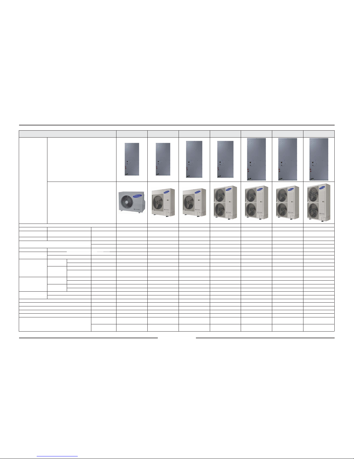
2-2 Product Specifications
ITEM
AC018KNZDCH/AA
AC018JXAD CH/AA
AC024KNZDCH/AA
AC024JX ADCH/AA
AC030KNZDCH/AA
AC030JX ADCH/AA
AC036KNZDCH/AA
AC036JX ADCH/AA
AC042KNZDCH/AA
AC042JX ADCH/A A
AC048KNZDCH/AA
AC048J XADCH/A A
AC054KNZDCH/AA
AC054K XADCH/A A
IMAGE
Indoor Unit
Outdoor Unit
Power Supply
1Φ, 208-230V, 60Hz 1Φ, 208-230V, 60Hz 1Φ, 208-230V, 60Hz 1Φ, 208-230V, 60Hz 1Φ, 208-230V, 60Hz 1Φ, 208-230V, 60Hz 1Φ, 208-230V, 60Hz
Performance Cooling/Heating
Btu/h 18,000 / 20,000 24,000 / 27,000 30,000 / 32,000 36,000 / 40,000 42,000 / 47,000 48,000 / 53,000 54,000 / 60,000
Power Consumption Cooling/Heating
kW 1.60 / 2.00 2.18 / 2.64 2.95 / 2.82 3.16 / 3.62 4.14 / 4.22 5.00 / 4.95 6.72 / 5.80
EER/COP Cooling/Heating
Btu/hW 11.25 / 10 11.01 / 10.23 10.17 / 11.35 11.39 / 11.05 10.14 / 11.14 9.6 / 10.71 8.04 / 10.34
Energy Grade
Energy Grade (C) SEER 20.1 SEER 19.5 SEER 19.6 SEER 19.0 SEER 18.4 SEER 18.0 SEER 17.1
Energy Grade (H) HSPF 10.5 HSPF 11.5 HSPF 10.4 HSPF 10.2 HSPF 9.6 HSPF 9.7 HSPF 9.0
Operation Current Cooling/Heating
A 7.1 / 8.7 9.8 / 11.6 13.0 / 12.3 14.1 / 15.8 18.0 / 18.3 21.3 / 21.6 28.7 / 24.7
Noise
(Cooling / Heating)
Indoor Unit
dBA 38 / 38 41 / 41 41 / 41 42 / 42 42 / 42 43 / 43 45 / 45
Outdoor Unit
dBA 48 / 48 50 / 50 50 / 52 49 / 51 51 / 53 53 / 55 56 / 56
Size
Net Dimension
(WxHxD)
Indoor Unit
mm 445 x 1,092 x 533 445 x 1,092 x 533 533 x 1,219 x 533 533 x 1,219 x 533 622 x 1,492 x 552 622 x 1,492 x 552 622 x 1,492 x 552
Outdoor Unit
mm 880 x 638 x 310 94 0 x 998 x 330 940 x 998 x 330 9 40 x 1,210 x 330 940 x 1,210 x 330 940 x 1,210 x 330 940 x 1420 x 330
Shipping
Dimension
(WxHxD)
Indoor Unit
mm 493 x 1,135 x 665 493 x 1,135 x 665 590 x 1,305 x 665 590 x 1,305 x 665 676 x 1,588 x 695 676 x 1,588 x 695 676 x 1,588 x 695
Outdoor Unit
mm 1,023 x 730 x 413 995 x 1,096 x 426 995 x 1,096 x 426 995 x 1,388 x 426 995 x 1,388 x 426 995 x 1,388 x 426 995 x 1598 x 426
Weight
Net
Indoor Unit
kg 44. 5 44.5 56.0 56.0 74.0 74.0 74.0
Outdoor Unit
kg 45.0 64.5 70.0 88.0 88.0 88.0 96.0
Shipping
Indoor Unit
kg 49.0 49.0 62.0 62.0 80.0 80.0 80.0
Outdoor Unit
kg 48 .0 69.5 74.0 98.0 98.0 98.0 106.0
Connecting Pi pe
Liquid
mm 6.35 (1/4") 6.35 (1/4") 9. 52 (3/8") 9.52 (3/8") 9.52 (3/8") 9. 52 (3/8") 9.52 (3/8")
Gas
mm 12.7 (1/2") 15.88 (5/8") 15.88 (5/8") 15.88 (5/8") 15.88 (5/8") 15.88 (5/8") 19.05 (3/4")
Refrigerant (R410A)
g 1300 2100 2600 2800 2800 2800 3500
Additional Refrigerant (R410A)
g/m 10 10 22 33 33 33 33
Standard
m 7.5 7.5 7.5 7.5 7.5 7.5 7.5
Extension Length (Maximum)
m 3 0 50 50 75 75 75 75
Extension Length (Elevation)
m 20 30 30 30 30 30 30
Option Code
Product Option
01E06C-10502027343B-370005
01E06C-105020-274750-
370005
01E06C-105020275A64-370005
01E06C-105020-276470-
370005
01E06C-105020277D8C-370005
01E06C-105020278CA0-370005
01E06C-10502027A0B4-370005
Installation Option
020000-100000-200000-
300000
020000-100000-200000-
300000
020000-100000-200000-
300000
020000-100000-200000-
300000
020000-100000-200000-
300000
020000-100000-200000-
300000
020000-100000-200000-
300000
2-4 Samsung Electronics
Item Description Code No. Q’ty Remark
2
:
1
(5
6
,1
6
7
5
8
&
7
,2
1
6
0
$
1
8
$
/
'(,1
675
8
&
&
,2
1
(
6
,6
7
5
8
=
,2
1
,
3
(5
/
8
6
2
0
$
1
8
$
/
'(,
1
6
7
5
8
ÄÌ(
6
0
$
1
8
(/
'8
7,/
,6
$
7
,2
1
*
(%
5
$
8
&
+
6$
1
:
(,6
8
1
*
6
S
O
X
W
W
\
S
H
5
R
R
P
$
L
U
&
RQ
G
L
W
L
R
Q
H
U
$
L
U
H
D
F
R
Q
G
L
F
L
R
Q
D
G
R
G
R
P
VW
L
F
R
V
L
V
W
H
P
D
6
S
O
L
W
&
R
Q
G
L
]
L
R
Q
D
W
R
U
H
G
D
U
L
D
S
H
U
D
P
E
L
H
Q
W
L
D
G
X
Q
L
W
Ø
6
H
S
D
U
D
W
H
$
S
D
U
H
O
K
R
G
H
D
U
F
R
Q
G
L
F
L
R
Q
D
G
R
W
L
S
R
6
S
O
L
W
&
O
L
P
D
W
L
V
H
XU
G
H
W
\
S
H
V
S
D
U
*
H
W
H
L
O
W
H
U
D
X
P
N
O
L
P
D
D
Q
O
D
J
H
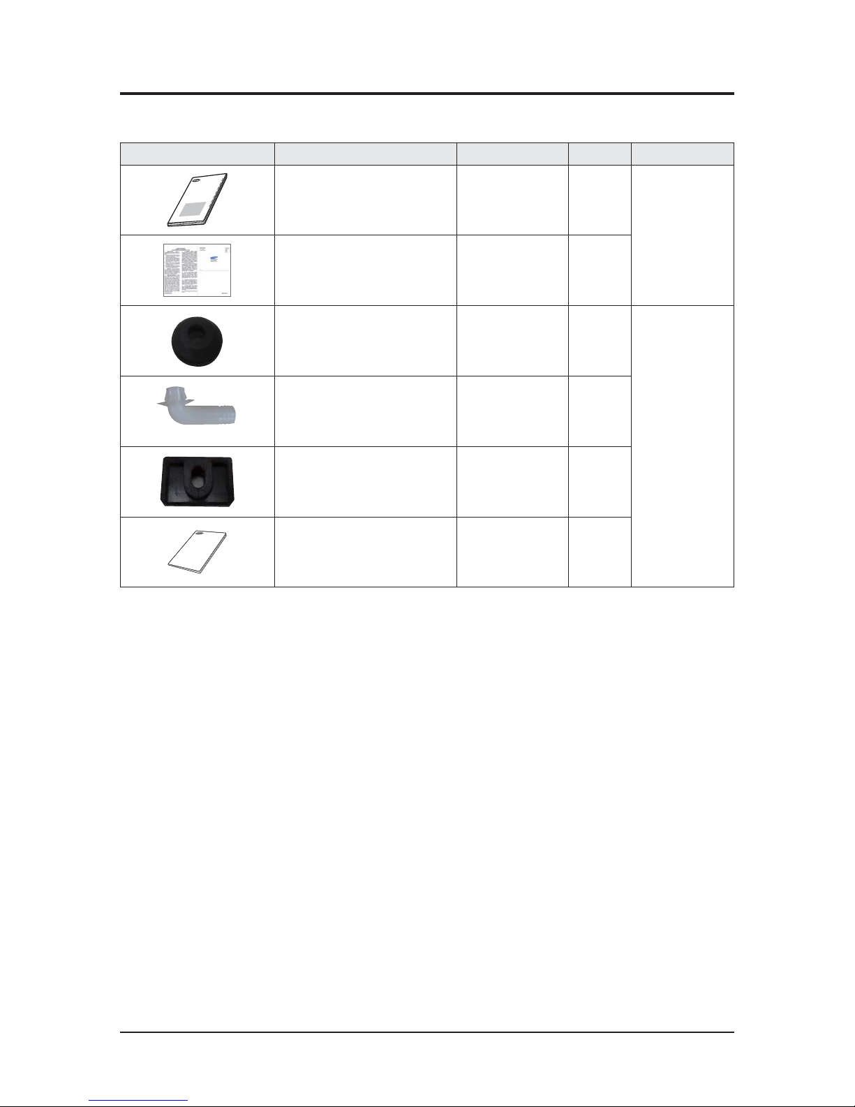
Installation manual - 1
Essential Offer
(Indoor Unit)
Card Warranty - 1
Cap Drain DB63-10355C 3
Essential Offer
(Outdoor Unit)
Drain Plug DB67-00806A 1
Rubber Leg DB73-20134A 4
Manual Install DB68-05462A 1
2-3 Specifications of optional items
2-3-1 Accessories
Samsung Electronics 3-1
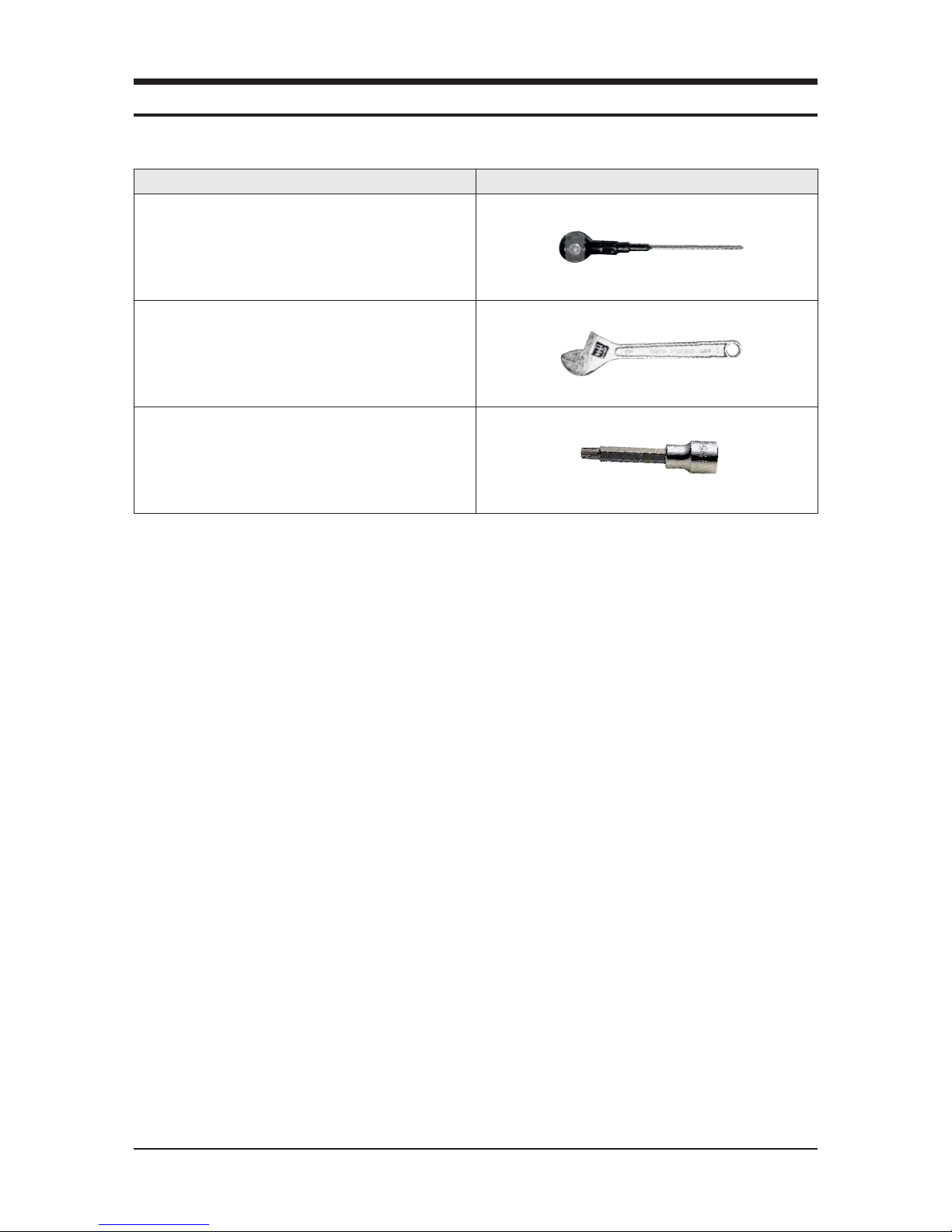
Item Remarks
+SCREW DRIVER
Adjustable Wrench
(8mm, 10mm, 13mm)
M6, M8 Hex Wrench
QNecessary Tools
3. Disassembly and Reassembly
3-2 Samsung Electronics
No Parts Procedure Remark
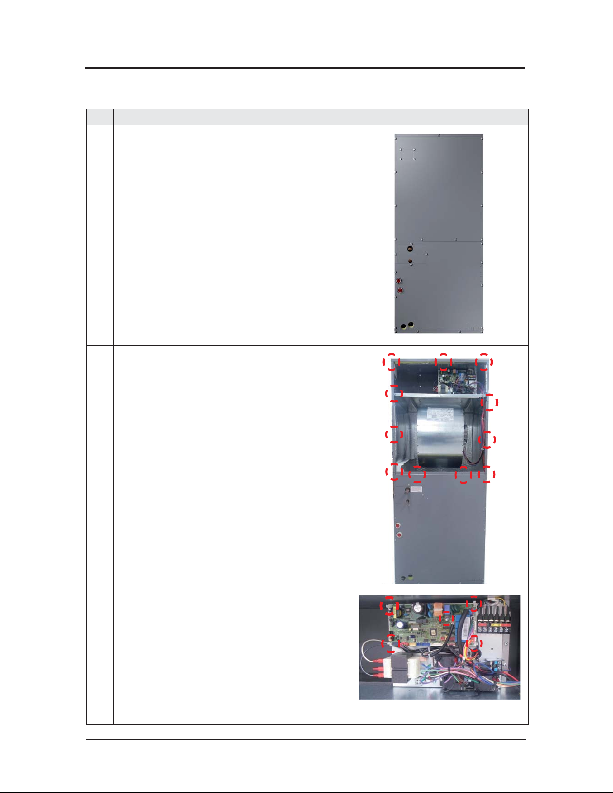
1 FRONT VIEW 1) Stop the operation of the air conditioner
and disconnect the main power supply.
2 Control-BOX 1) Loosen 11 of the front screw(CCW) and
detach the Cabinet Front Up.
2) Disconnect the Connector Wire that is
connected to the indoor unit's PBA
3) Unscrew the 1 fixed screws on middle of
the PBA and 4 fixed PBA HOLDER, and
disassemble the PBA from the indoor
unit.
(Use + Screw Driver)
3-1 Indoor Unit
QV-AHU
- AC018/024/030/036/042/048/054KNZDCH/AA
Disassembly and Reassembly
Samsung Electronics 3-3
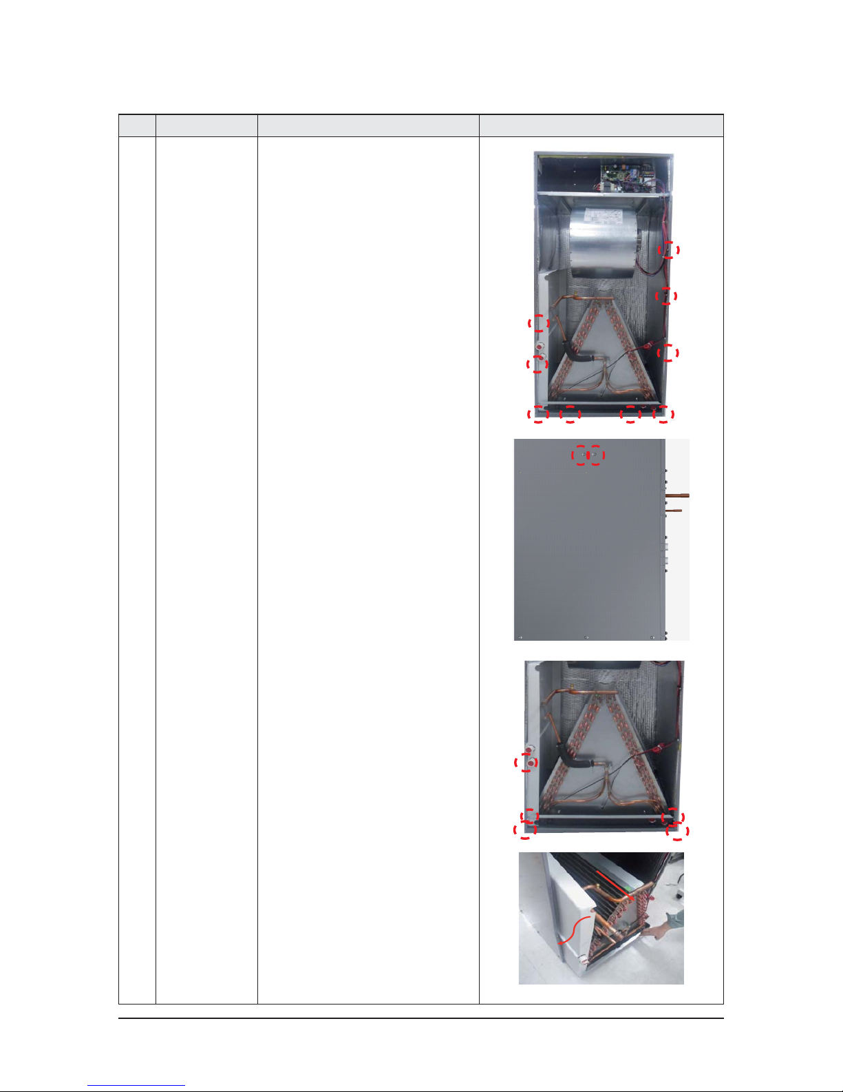
No Parts Procedure Remark
3 DRAIN PAN 1) Loosen 11 of the front screw(CCW) and
detach the Cabinet Front Down.
2) Loosen 2 of the Left side screw(CCW).
3) Loosen 5 of the front screw(CCW) and
detach the 2 Bracket drain and 1 Bracket
Low
4) Pull the Heat Exchanger and Drain.
5) Detach the Drain from indoor Unit.
Disassembly and Reassembly
3-4 Samsung Electronics
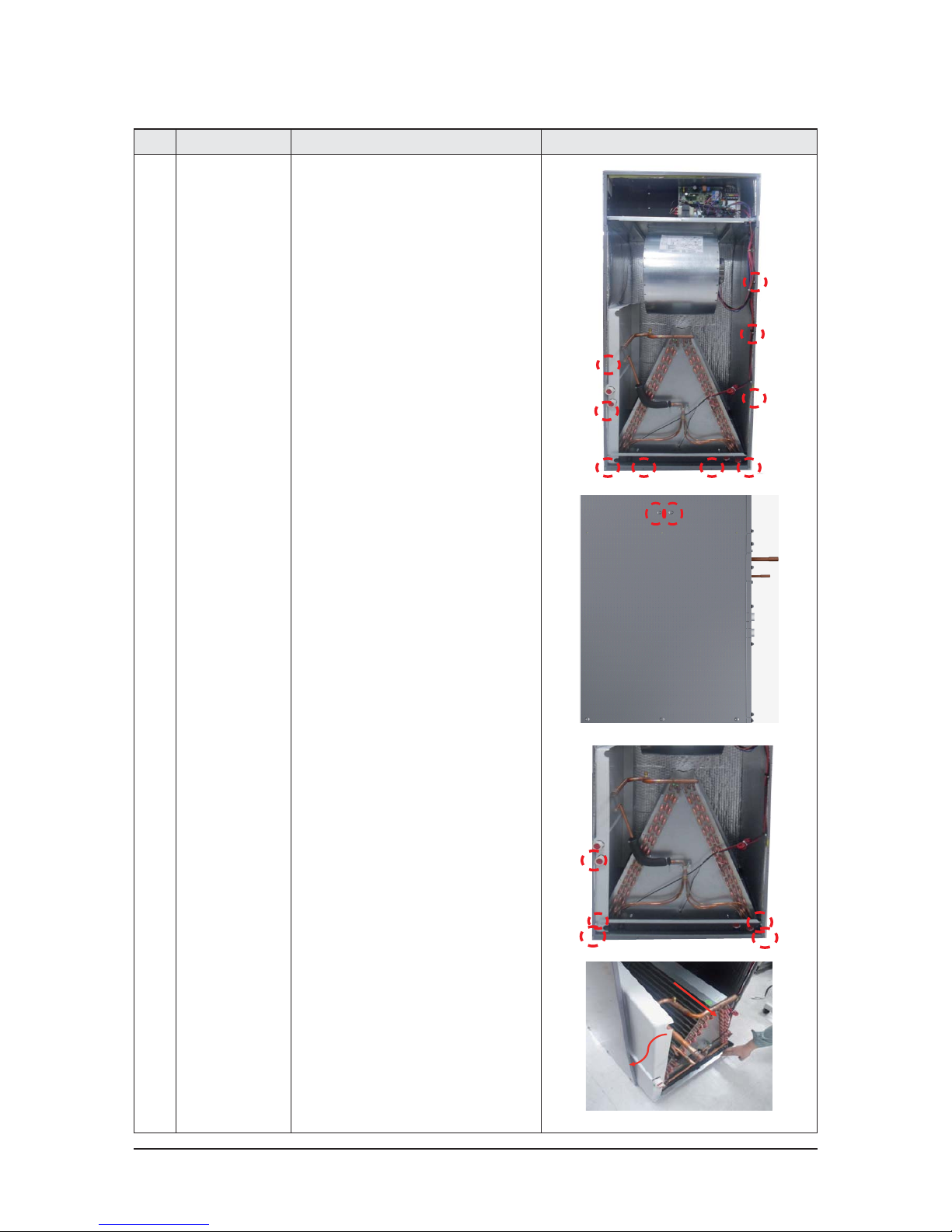
No Parts Procedure Remark
4 Heat Exchanger 1) Loosen 11 of the front screw(CCW) and
detach the Cabinet Front Down.
2) Loosen 2 of the Left side screw(CCW).
3) Loosen 5 of the front screw(CCW) and
detach the 2 Bracket drain and 1 Bracket
Low.
4) Disconnect the Connector Wire that is
connected to the Heat Exchanger.
5) Pull the Heat Exchanger and Drain.
6) Detach the Heat Exchanger.
Disassembly and Reassembly
Samsung Electronics 3-5
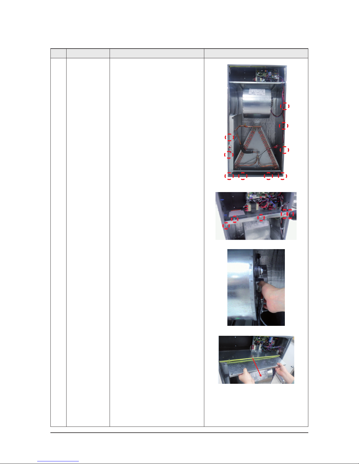
No Parts Procedure Remark
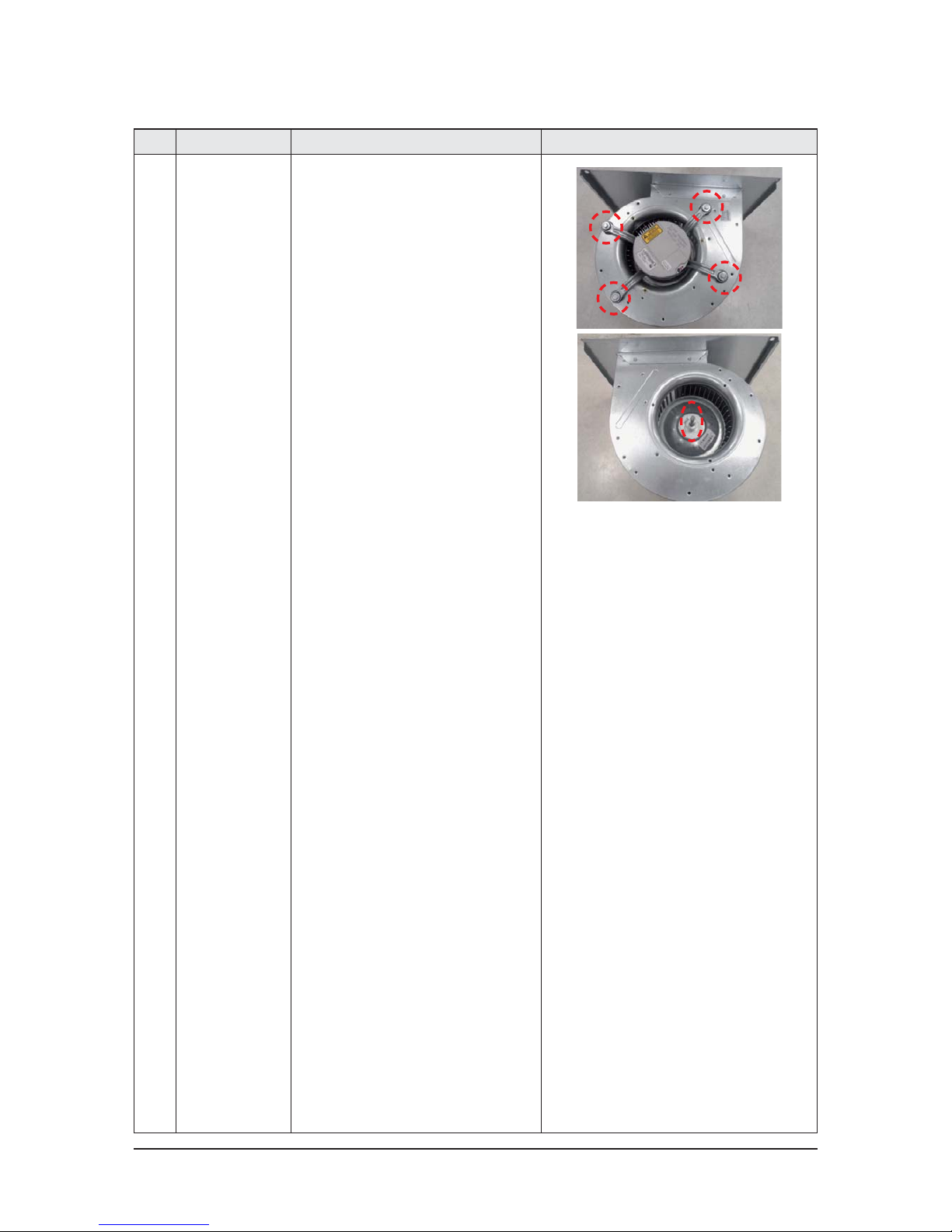
5 FAN & MOTOR 1) Loosen 11 of the front screw(CCW) and
detach the Cabinet Front Down.
2) Loosen 6 of the Front screw(CCW) and
detach the Bracket.
3) Disconnect the Connector Wire that is
connected to the Motor.
5) Pull the A'ssy Fan Blower.
Disassembly and Reassembly
3-6 Samsung Electronics
No Parts Procedure Remark
6) Loosen 4 of the screw and 1 nut on the
CASE and Detach the motor and fan.
Disassembly and Reassembly
Samsung Electronics 3-7
No Parts Procedure Remark
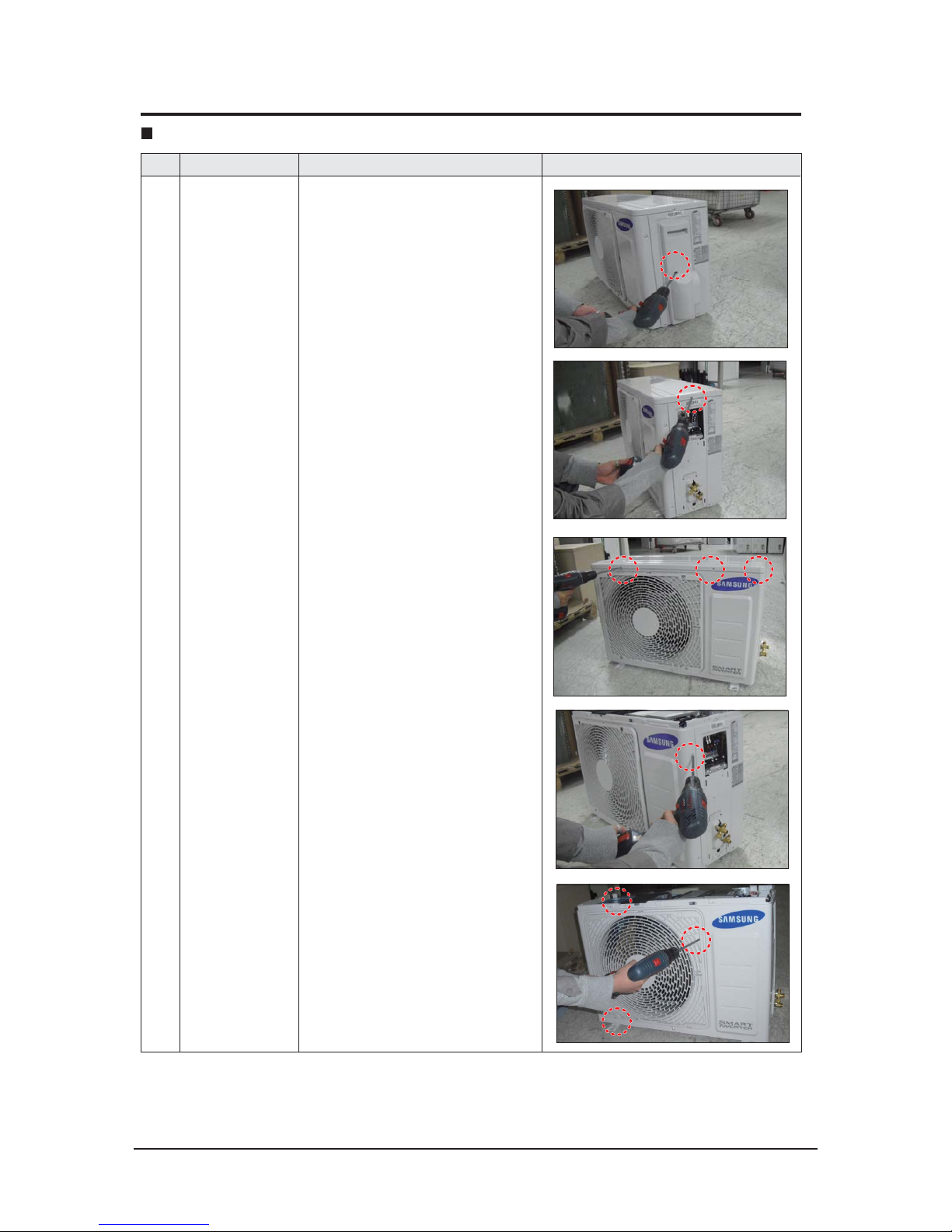
1 common work 1) loosen 1 pcs screw of cover control,and
detach it.
2) loosen 5 pcs screws on both right and
left cabniet side edges and to detach the
cover-top
3) Loosen 7 screwsxed to disassemble
cabi-front , and detach it.
AC018JXADCH
3-2 Outdoor Unit
Disassembly and Reassembly
3-8 Samsung Electronics
No Parts Procedure Remark
common work 4) loosen 7 screws to disassemble the cabi-
right ,and detach it.
5) loosen 2 screws to disassemble steel-bar.
6) loosen 3 screws to disassemble cabi-left.
Disassembly and Reassembly
Samsung Electronics 3-9
No Parts Procedure Remark
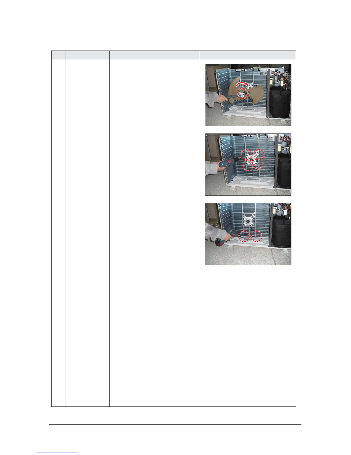
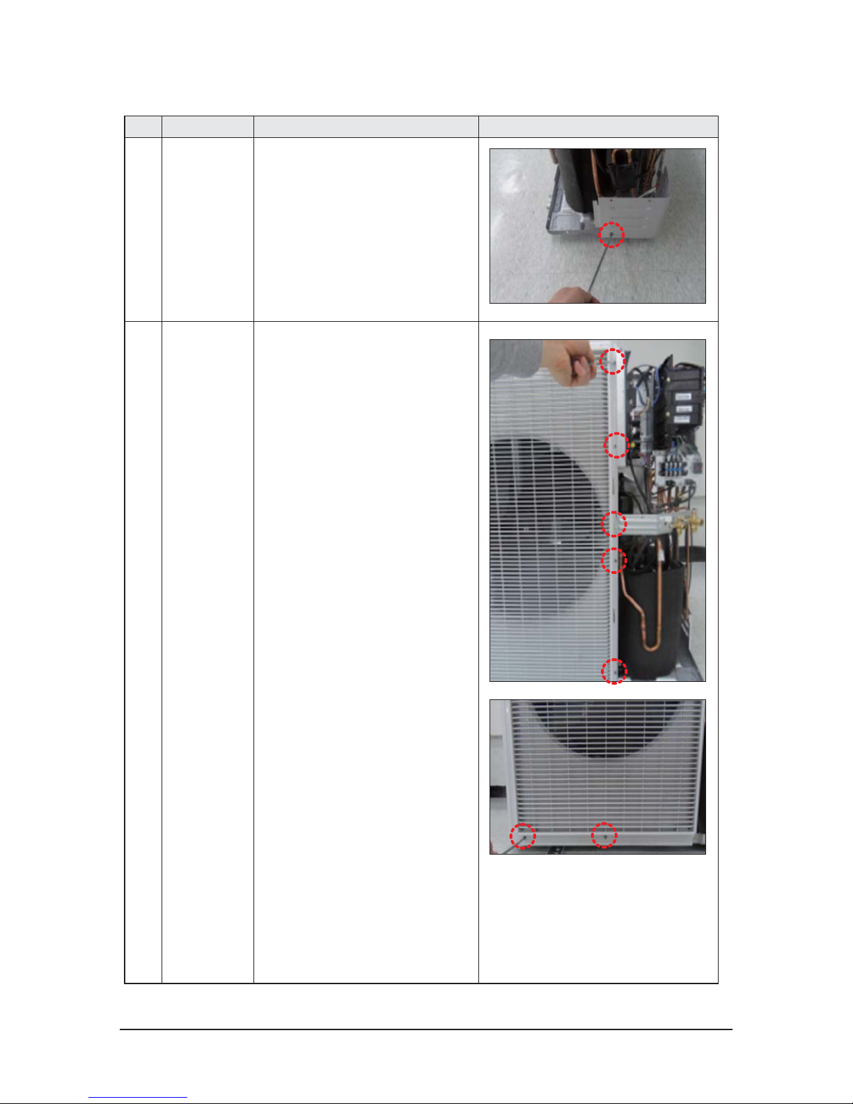
2 fan&motor 1) loosen 1 screw as indication and detached
the fan.
2) loosen 4 pcs motor screws and disconnect
the wire betwwen assy control out and motor.
3) loosen 2 pcs bracket-motor screw and
detach it.
Disassembly and Reassembly
3-10 Samsung Electronics
No Parts Procedure Remark
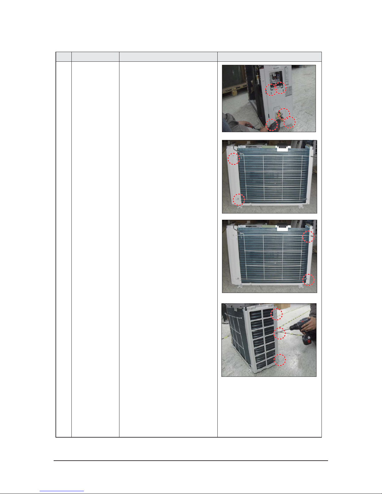
3 assy control out 1) lossen xing 1 screw from cover -control
2) detach several connections from assy control out, take out assy control out.
4 Heat exchanger 1) Release the refrigerant at rst
2) Looosen xing screw on both side.
3) disaessembly the pipes in both inlet and
outlet with welding torch.
4) detach the heat exchanger.
Disassembly and Reassembly
Samsung Electronics 3-11
No Parts Procedure Remark
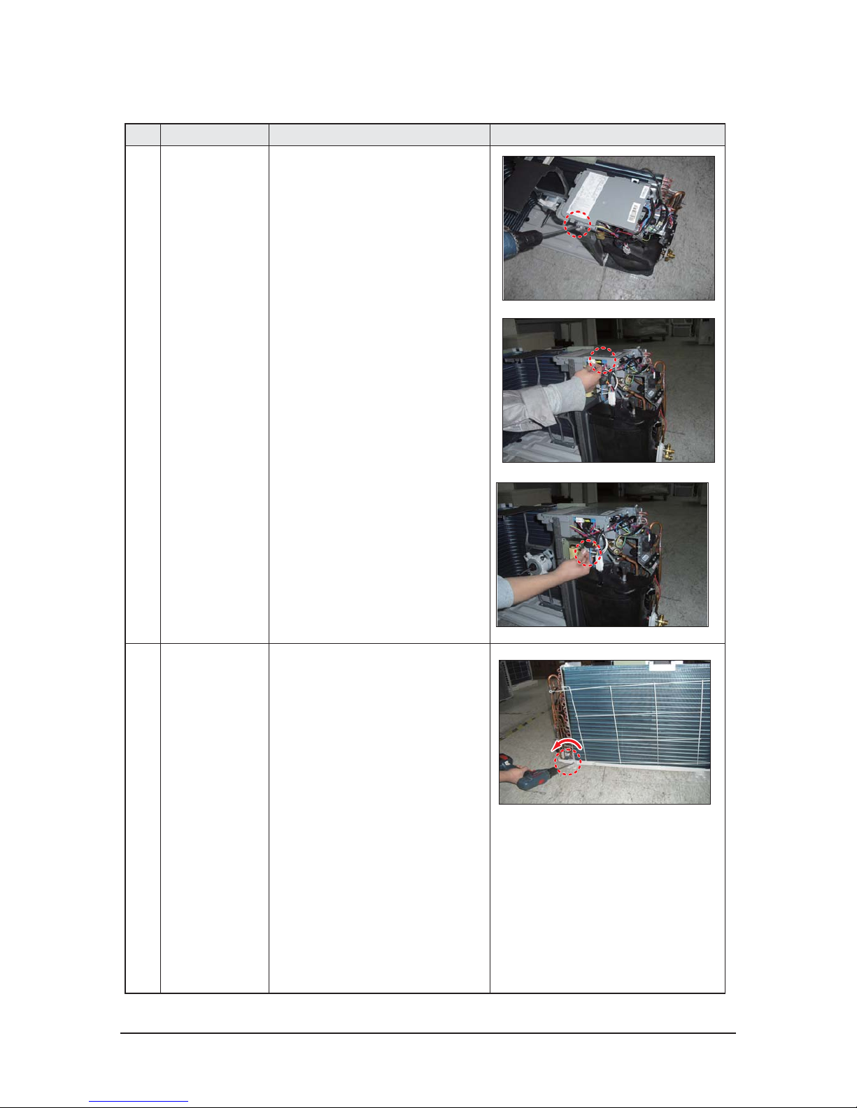
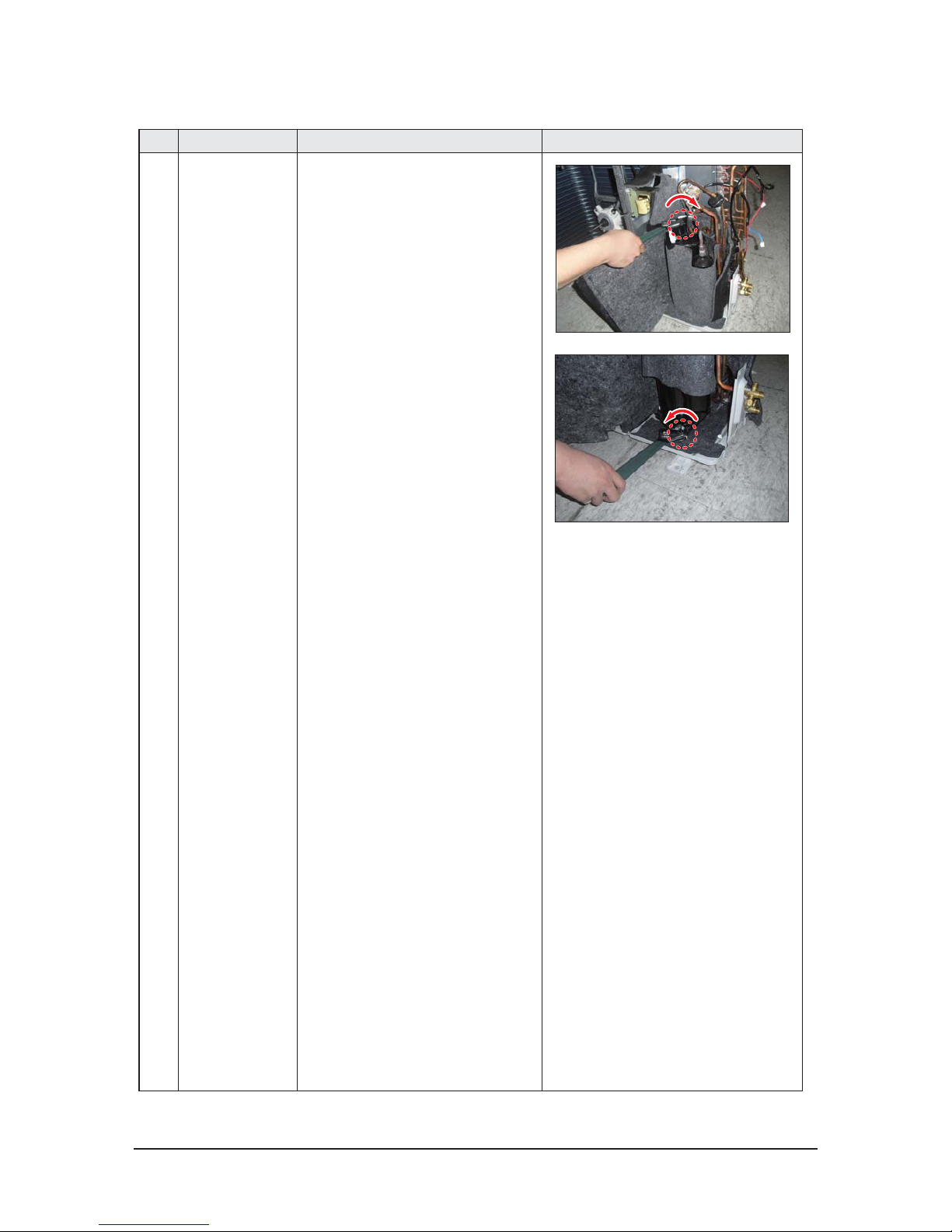
5 compressor 1) disconnect the compressor lead wire .
2)disassembly the felt comp sound.
loosen the 3 bolts at the bottom of
Disassembly and Reassembly
3-12 Samsung Electronics
No Parts Procedure Remark
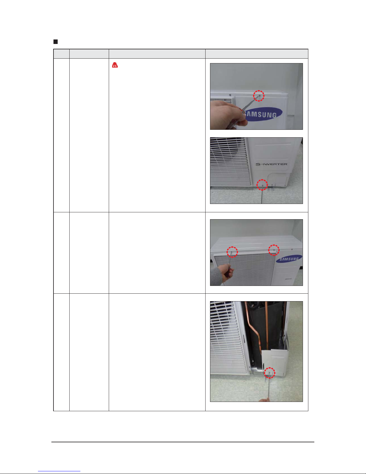
1 Cabi Front RH
You must turn o the Power before
disassembly.
1) Unscrew and remove two mounting screw
in the Cabinet Front RH. (Use +Screw Driver)
2 Cabi Top 1) Unscrew and remove 9 screws
on each side of the Cabinet-Top.
(Use +Screw Driver)
3 Cabi Install Front 1) Unscrew and remove 1 screw
in the Cabinet-Install Front.
(Use +Screw Driver)
AC024JXADCH, AC030JXADCH
Disassembly and Reassembly
Samsung Electronics 3-13
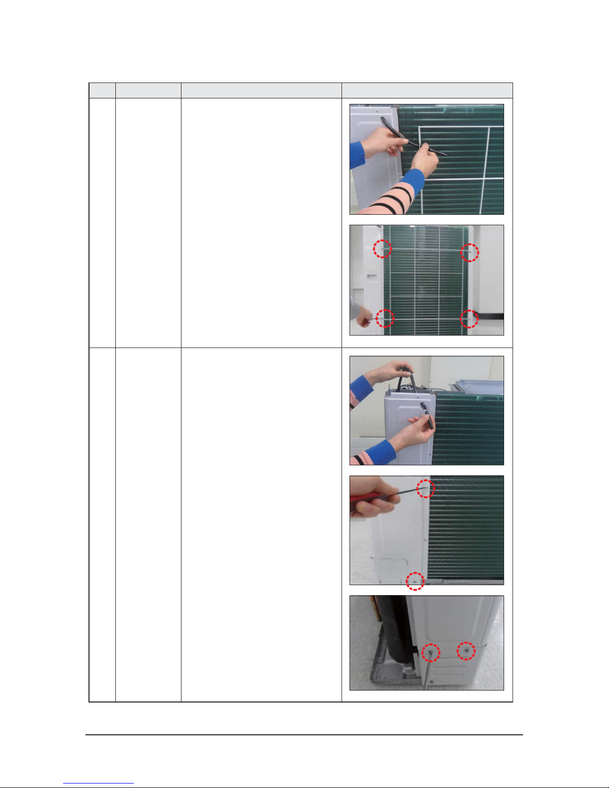
No Parts Procedure Remark
4 Guard Cond 1) Pull the sensor from Guard Cond.
2) Unscrew and remove 4 screws
in the Guard Cond.
(Use +Screw Driver)
5 Cabi Back RH 1) Pull the sensor from Cabi Back RH.
2) Unscrew and remove 4 screws
on each side of the Cabinet Back RH.
(Use +Screw Driver)
Disassembly and Reassembly
3-14 Samsung Electronics
No Parts Procedure Remark
6 Cabi Install Back 1) Unscrew and remove 1 screw
in the Cabinet-Install Back.
(Use +Screw Driver)
7 Cabi Front LF 1) Unscrew and remove 10 screws
in the Cabinet-Front LF.
(Use +Screw Driver)

Disassembly and Reassembly
Samsung Electronics 3-15
No Parts Procedure Remark
8 Fan 1) Turn 2 mounting nuts as shown in the
picture and remove it. (Use Adjustable
Wrench)

Disassembly and Reassembly
3-16 Samsung Electronics
No Parts Procedure Remark
9 Motor 1) Separate the Fan Propeller.
2) Unscrew and remove the 8 Motor mounting
screws. (Use +Screw Driver)
3) Disconnect the Motor wire From
Ass'y Control Out.
10 Bracket Motor 1) Unscrew and remove 2 mounting screws
in Bracket Motor. (Use +Screw Driver)

Disassembly and Reassembly
Samsung Electronics 3-17
No Parts Procedure Remark
11 Control Out 1) Disconnect 4 Connecters From
Ass'y Control Out.
2) Unscrew and remove 1 mounting screw
in Control Out. (Use +Screw Driver)
3) Separate Ass'y Control Out.

Disassembly and Reassembly
3-18 Samsung Electronics
No Parts Procedure Remark
12 Ass'y 4way Valve 1) Purge the Coolant rst.
2) Unscrew and remove 2mounting screws
in muer.
3) Unscrew and remove 2 mounting screws
in Service Valve. (Use +Screw Driver)
4) Separate the pipe from the Entrance/Exit
using a welder.
When removing the compressor,
Heat Exchanger, and Pipe, purge the
Coolant inside the Compressor
completely and remove the pipe
with a welding ame.

Disassembly and Reassembly
Samsung Electronics 3-19
No Parts Procedure Remark
13 Ass;y EEV Valve 1) Unscrew and remove 2 mounting screws
in Service Valve. (Use +Screw Driver)
2) Separate the pipe from the Entrance/Exit
using a welder.
14 Compressor 1) Unscrew and remove 1 mounting nut
in Cover Terminal. (Use Adjustable Wrench)
2) Separate the Compressor Felt Sound.

Disassembly and Reassembly
3-20 Samsung Electronics
No Parts Procedure Remark
3) As shown in the picture, unscrew and
remove 3 mounting screws from the
bottom. (Use Adjustable Wrench)
15 Cond Out 1) Unscrew and remove 3 screws
on each side of the Assy Cond Out.
(Use +Screw Driver)
2) Separate the Compressor Felt Sound.

Disassembly and Reassembly
Samsung Electronics 3-21
No Parts Procedure Remark
1 Cabi Front RH
You must turn o the Power before
disassembly.
1) Unscrew and remove two mounting
screw in the Cabinet Front RH.
(Use +Screw Driver)
2 Cabi Top
1) Unscrew and remove 9 screws
on each side of the Cabinet-Top.
(Use +Screw Driver)
3 Cabi Install Front
1) Unscrew and remove 1 screw
in the Cabinet-Install Front.
(Use +Screw Driver)
4 Guard Cond
1) Pull the sensor from Guard Cond.
2) Unscrew and remove 4 screws
in the Guard Cond.
(Use +Screw Driver)
QAC036JXADCH, AC042JXADCH, AC048JXADCH, AC054KXADCH

Disassembly and Reassembly
3-22 Samsung Electronics
No Parts Procedure Remark
5 Cabi Back RH
1) Pull the sensor from Cabi Back RH.
2) Unscrew and remove 4 screws
on each side of the Cabinet Back RH.
(Use +Screw Driver)
6 Cabi Install Back
1) Unscrew and remove 1 screw
in the Cabinet-Install Back.
(Use +Screw Driver)
7 Cabi Front LF
1) Unscrew and remove 10 screws
in the Cabinet-Front LF.
(Use +Screw Driver)
8 Fan
1) Turn 2 mounting nuts as shown in
the picture and remove it.
(Use Adjustable Wrench)

Disassembly and Reassembly
Samsung Electronics 3-23
No Parts Procedure Remark
9 Motor
1) Separate the Fan Propeller.
2) Unscrew and remove the 8 Motor
mounting
screws. (Use +Screw Driver)
3) Disconnect the Motor wire From
Ass'y Control Out.
10 Bracket Motor
1) Unscrew and remove 2 mounting
screws in Bracket Motor.
(Use +Screw Driver)
11 Control Out
1) Disconnect 4 Connecters From
Ass'y Control Out.
2) Unscrew and remove 1 mounting
screw in Control Out.
(Use +Screw Driver)
3) Separate Ass'y Control Out.

Disassembly and Reassembly
3-24 Samsung Electronics
No Parts Procedure Remark
12 Assy 4way Valve
1) Purge the Coolant rst.
2) Unscrew and remove 2 mounting
screws in Service Valve. (Use +Screw
Driver)
3) Separate the pipe from the
Entrance/Exit using a welder.
When removing the compressor, Heat Exchanger, and Pipe,
purge the Coolant inside the
Compressor completely and
remove the pipe with a welding
ame.
13 Assy EEV Valve
1) Unscrew and remove 2 mounting
screws in Service Valve.
(Use +Screw Driver)
2) Separate the pipe from the Entrance/
Exit using a welder.

Samsung Electronics 4-1
4. Troubleshooting
4-1 Indoor Display Error and Check Method
■Error detection and reoperation
● If error occurs during the operation, badness is indicated by LED flickering and all operation is stopped except LED.
● When reoperating by remote control and switch determine the error mode after normal operation.
4-1-1Indoor unit LED lamp display at error detecting
Abnormal conditions
Indicators
Remarks
Concealed Type
Green Red
Standard Type
Power reset. XXXX
Error of Room sensor in the indoor unit.(Open/Short) X X XX
Error of EVA-IN,EVA-OUT sensor in the indoor unit.
(Open/Short)
X XX
Error of Fan motor in the indoor unit. X X X
X
1. Error of Outdoo.r
2. Thermal Fuse Open Error of Indoor's Terminal Block.
XX
1. Clogging of outdoor's service valve.
2. the refrigerant leakage .
XX
Detection of the float switch. X X X
1. Error of EEPROM.
2. Error of Option setting.
1. Error of Outdoor Temp. sensor.
2. Error of Cond Temp. sensor.
3. Error of discharge Temp. sensor.
XX X
1. No communication for 2 minutes between indoor units
(Communication error for more than 2 minutes)
2. Indoor unit receiving the communication error from
outdoor unit
3. Outdoor unit tracking 3 minutes error
4. When sending the communication error from the outdoor unit, the mismatching of the communication numbers and installed numbers after completion of tracking.
(Communication error for more than 2 minutes)
XX
X
1. Indoor unit error
(Display is unrelated
with operation)
2. Outdoor unit error
(Display is unrelated
with operation)
LED Display on the receiver & display unit
●: On, ◑: Flickering, X : OFF
◆ If you turn off the air conditioner when the LED is flickering, the LED is also turned off.

Troubleshooting
4-2 Samsung Electronics
4-1-2 Wired Remocon Error Display
- If an error occurs, ( ) is displayed on the wired remote controller.
- If you would like to see an error code, press the Test button.
Error mode Contents Error type
Indoor unit communication error Communication error
Duplicated address setting error Communication error
No response error address from indoor unit Communication error
Indoor temperature sensor (open/short error) Indoor sensor error
Indoor unit Eva In sensor (Open/Short) Indoor sensor error
Indoor/outdoor communication error (1 min) Communication error
Communication error between indoor/outdoor INVlMAIN MICOM (1 min) Communication error
Outdoor temperature sensor error Outdoor sensor error
COND temperature sensor error Outdoor sensor error
[Inverter] Emission temperature sensor error Outdoor sensor error
Detection of Indoor Freezing (when Comp. Stops) Outdoor unit protection control error
Protection of Outdoor Overload (when Comp. Stops) Outdoor unit protection control error
Emission temperature excessively high Outdoor unit protection control error
High pressure blockage error
(Refrigerant completely Leakage error)
Self diagnostic error
Heating operation blocked Self diagnostic error
Cooling operation blocked Self diagnostic error
Outdoor fan 1 error Self diagnostic error
[Inverter] Compressor startup error Outdoor unit protection control error
[Inverter] Total current error/PFC over current error Outdoor unit protection control error
OLP Overheat and Comp. Stop Outdoor unit protection control error
[Inverter] IPM over current error Outdoor unit protection control error
Compressor V limit error Outdoor unit protection control error
DC LINK over/low voltage error Outdoor unit protection control error

Troubleshooting
Samsung Electronics 4-3
Wired remote controller (cont.)
Error mode Contents Error type
[Inverter] Compressor rotation error Outdoor unit protection control error
[Inverter] Current sensor error Outdoor unit protection control error
[Inverter] DC LINK voltage sensor error Outdoor unit protection control error
EEPROM Read/Write error Outdoor unit protection control error
[Inverter] OTP error Outdoor unit protection control error
AC ZERO CROSSING SIGNAL OUT error Outdoor unit protection control error
Compressor LOCK error Outdoor unit protection control error
Outdoor fan 2 error Self diagnostic error
IPM Overheat Error for Outdoor Unit Inverter Comp. Outdoor unit protection control error
Gas leak error Self diagnostic error
Capacities not matched Outdoor unit protection control error
Communication error between the indoor unit and wired remote controller Wired remote controller error
Communication error between the Master and Slave wired remote controllers Wired remote controller error
Do not install the electronic heater in the external supply duct connected to the AHU.

Troubleshooting
4-4 Samsung Electronics
Indoor unit display
X (Operation) X (Defrost) (Timer) X(Fan) X (Filter)
Wire remote controller display
E121
Symptom
Error of Room sensor in the indoor unit(Open/Short)
Failure
Short or leakage of the Room sensor
4-2 Troubleshooting by symptoms
4-2-1 Indoor temperature sensor (open/short)
Yes
No
No
In this case, is the resistance
value out of range in the temperature
table on the right?
Yes
Is indoor temperature
sensor disconnected from the
connector in PCB?
Restart the system after replacing the PCB
Restart the system after connecting
to the PCB connector
Indoor temperature sensor
failure (replace)
Remove the indoor temperature sensor
connector from the PCB and measure the
resistance between two terminals
Current temperature (°C)
Resistance
(kΩ)
40 5.800
35 6.900
30 8.300
25 10.00
20 12.10
15 14.70
10 18.00
5 22.00
0 28.30
-5 33.90
-10 42.30
<Temperature sensor
resistance value>

Troubleshooting
Samsung Electronics 4-5
Indoor unit display
(Operation) X (Defrost) (Timer) X(Fan) X (Filter)
Wire remote controller display
E122, E123
Symptom
Error of EVA-IN,EVA-OUT sensor in the indoor unit(Open/Short)
Failure
Short or leakage of the EVA sensor
4-2-2 Eva in and out sensor (open/short)
Yes
No
No
In this case, is the resistance
value out of range in the temperature table
on the right?
Yes
Is the indoor heat exchanger
temperature sensor connector disconnected
from the PCB?
Restart the system after replacing the PCB
Restart the system after
connecting the connector to PCB
Failure of the indoor heat
exchanger temperature sensor
(replace)
Remove the indoor heat exchanger
temperature sensor connector from
the PCB and measure the resistance
between two terminals
Current temperature (°C)
Resistance
(kΩ)
40 5.800
35 6.900
30 8.300
25 10.00
20 12.10
15 14.70
10 18.00
5 22.00
0 28.30
-5 33.90
-10 42.30
<Temperature sensor
resistance value>

Troubleshooting
4-6 Samsung Electronics
Indoor unit display
X (Operation) X (Defrost) X(Timer) (Fan) X (Filter)
Wire remote controller display
E154
Symptom
Error of Fan motor in the indoor unit
Failure
Fan error
4-2-3 Fan error
No
No
Yes
Yes
Is the motor connector
disconnected from the PCB?(CN301)
Is there foreign substance
stuck in the motor fan?
Replace the PCB and restart the unit.
Connect the connector to
PCB and restart the unit
Remove the foreign substance
and restart the unit

Troubleshooting
Samsung Electronics 4-7
Indoor unit display
X (Operation) X (Defrost) (Timer) (Fan) (Filter)
Wire remote controller display
E198
Symptom
Error of Terminal Block's Terminal Fuse(Open)
Failure
Fuse open
4-2-4 Terminal Block's Terminal Fuse(Open)
No
No
Yes
Is the resistance 0Ω ?
Yes
Is the wire connector
disconnected from the terminal block and
PCB?(CN140)
Replace the PCB and restart the unit
Connect the connector to
PCB and terminal block before
restart the unit
Replace the Terminal Block and
restart the unit
Remove the wire connector from the PCB
and measure the resistance between two
terminals

Troubleshooting
4-8 Samsung Electronics
Indoor unit display
(Operation) X (Defrost) X (Timer) (Fan) (Filter)
Wire remote controller display
E422
Symptom
Clogging of outdoor's service valve
Failure
Valve clog
4-2-5 Outdoor's service valve(Clog)
Yes
No
Is the outdoor service valve clogging?
Replace the PCB and restart the unit.
Open the outdoor's service valve.

Troubleshooting
Samsung Electronics 4-9
4-2-6 EEPROM error
Indoor unit display
(Operation) (Timer) (Fan) (Filter) (Defrost)
Wire remote controller display
E162
Symptom
EEPROM PCB disconnected from the MAIN PCB
Failure
Option error
Yes
Yes
No
No
Is the EEPROM PCB
disconnected from the MAIN PCB?
(CN201)
Is the error mode disappear ?
Connect the EEPROM PCB to MAIN PCB
The indoor unit work normaly
Connect the EEPROM PCB to
MAIN PCB
and restart the unit
Replace the PCB and
restart the unit

Troubleshooting
4-10 Samsung Electronics
4-2-7 Option error
Indoor unit display
(Operation) (Timer) (Fan) (Filter) (Defrost)
Wire remote controller display
E163
Symptom
EEPROM option setting error
Failure
Option error
Yes
No
Is the error mode disappear ?
Input the right option to EEPROM PCB
The indoor unit work normaly
Replace the PCB and
restart the unit

Troubleshooting
Samsung Electronics 4-11
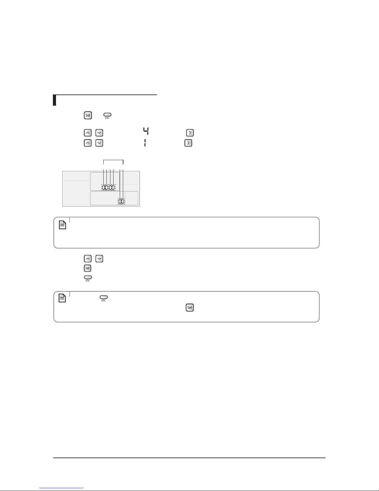
In order to set the indoor unit option code use the wired remote controller and follow the directions below.
1) Press the
and buttons at the same time for more than 3 seconds and then a Main menu will be
displayed.
2) Press the
/ button to select and then press button to enter a Sub-menu setting screen.
3) Press the
/ button to select and then press button to enter a Indoor unit option code setting
screen.
4) Press the
/
button to set the option code in order. Press button to go to the next page.
5) Press the
button to save and complete the option setting.
6) Press the
button to exit to normal mode.
t Option code will not be applied if you don’t press the
t Setting indoor unit option code is only possible in Master wired remote controller.
You can only check the indoor unit option code in Slave wired remote controller.
t Setting indoor unit option code is possible when one indoor unit is connected. If more than 2
indoor units are connected, you can only check the Master indoor unit option code.
t Press the
button anytime during setup to exit without setting.
NOTE
NOTE
t The first digit represents the page number and the remaining five digits are option codes.
t The option code which is currently setting will icker.
Main Menu
Sub-menu
123 546
Data bit
12 34 56
Option CodePage number
SEG1 SEG2 SEG3 SEG4 SEG5 SEG6
0
77777
Page number
SEG7 SEG8 SEG9 SEG10 SEG11 SEG12
1
77777
Page number
SEG13 SEG14 SEG15 SEG16 SEG17 SEG18
2
77777
Page number
SEG19 SEG20 SEG21 SEG22 SEG23 SEG24
3
77777
Page number
4-3 Setting the indoor unit option code
Troubleshooting
4-12 Samsung Electronics
Set the indoor unit address and installation option with remote controller option. Set the each option
separately since you cannot set the ADDRESS setting and indoor unit installation setting option at the same
time. You need to set twice when setting indoor unit address and installation option.
Setting an indoor unit address
1) Press the and buttons at the same time for more than 3 seconds and then a Main menu will be
displayed.
2) Press the
/ button to select and then press button to enter a Sub-menu setting screen.
3) Press the
/ button to select and then press button to enter a Indoor Address setting screen.
4) Press the
/ button to set the Indoor unit Main/RMC Address.
5) Press the
button to save and complete the option setting.
6) Press the
button to exit to normal mode.
t Press the button anytime during setup to exit without setting.
t Address will not be applied if you don't press
button.
t Setting Main/RMC Address of an Indoor unit is available only with a master wired remote controller.
NOTE
NOTE
t The Main/RMC Address which is currently setting will flicker.
t Data bit 1 and 2 present Indoor unit main address checking
t Data bit 3 and 4 present Indoor unit main address setting(outdoor unit reset is needed to set).
4-3-1 Setting an indoor unit address and installation option
12 34 56
Data bit

Troubleshooting
Samsung Electronics 4-13
Setting an indoor unit installation option
In order to check and set the indoor unit installation option code use the wired remote controller and
follow the directions below.
1) Press the
and buttons at the same time for more than 3 seconds and then a Main menu will be
displayed.
2) Press the
/ button to select and then press button to enter a Sub-menu setting screen.
3) Press the
/ button to select and then press button to enter a Indoor unit installation option
code setting screen.
4) Press the
/ button to set the installation option code in order. Press button to go to the
next page.
SGE1 SGE2 SGE3 SGE4 SGE5 SGE6
0 2 RESERVED
Exterior
temperature
sensor
Central control RESERVED
SEG7 SEG8 SEG9 SEG10 SEG11 SEG12
1 RESERVED RESERVED Use of Heater RESERVED Master / Slave
SEG13 SEG14 SEG15 SEG16 SEG17 SEG18
2 External control
External control
output
RESERVED Buzzer RESERVED
SEG19 SEG20 SEG21 SEG22 SEG23 -
3
Individual control
of a remote
controller
Heating setting
compensation
RESERVED RESERVED -
t The rst digit represents the page number and the remaining ve digits are installation option.
t The total option codes are 24 digits. You can set six digits at a time and it is distinguished by page
number (0, 1, 2, 3).
NOTE

Troubleshooting
4-14 Samsung Electronics
Option No. : 02XXXX-1XXXXX-2XXXXX-3XXXXX
Option SEG1 SEG2 SEG3 SEG4 SEG5 SEG6
Explanation PAGE MODE
RESERVED
Use of external
temperature
sensor
Use of central
control
RESERVED
Indication and Details
Indication Details Indication Details Indication Details Indication Details
02
0 Disuse 0 Disuse
1 Use 1 Use
Option SEG7 SEG8 SEG9 SEG10 SEG11 SEG12
Explanation PAGE Use of drain pump Use of Hot Coil Use of Heater
RESERVED
Master / Slave
Indication and Details
Indication Details
RESERVED RESERVED
Indication Details Indication Details
1
0 Disuse 0 slave
1Use
1 master
--
Option SEG13 SEG14 SEG15 SEG16 SEG17 SEG18
Explanation PA GE
Use of external
control
Setting the
output of external
control
RESERVED
Buzzer control
RESERVED
Indication and Details
Indication Details Indication Details Indication Details Indication D etails
2
0 Disuse 0 Thermo on 0
Use of
buzzer
1
ON/OFF
Control
1
Operation
on
1
Non use
of buzzer
2
OFF
Control
3
WINDOW
ON/OFF
Control
Option SEG19 SEG20 SEG21 SEG22 SEG23 -
Explanation PA GE
control of a remote
controller
Heating setting
compensation
RESERVED RESERVED
-
Indication and Details
Indication Details Indication Details Indication D etails -
3
0 or 1 Indoor 1 0 Disuse
-
2 Indoor 2 1 2°C
3 Indoor 3
2 5°C
4 Indoor 4
5. Press the button to save and complete the option setting.
6. Press the
button to exit to normal mode.
t Press button anytime during setup to exit without setting.
t Option code will not be applied if you don't press
button.
t Setting Installation option code is available only with a master wired remote controller.
t Setting Installation option code is available when there is one on one connection between a wired
remote controller and an indoor unit.
NOTE

Troubleshooting
Samsung Electronics 4-15
Selecting motor speed
Selecting the Constant Torque Blower Speed
This air handler uses a Constant Torque high eciency motor. This motor operates on 240 VAC. The motor speed
taps are 24 VAC, 0.03 amps, 60 Hz, 1 PH. The speed taps can be adjusted according to installation needs. Table 4
shows the motor lead connection labeling and the connection denitions. See blower tables in later section for
airow data.
Total 24 VAC circuit amps are 0.14 amps.
Change Motor Speeds
1. Turn o all electrical supply circuits to the air handler at the main service (House Circuit Breaker) panel.
2. Remove the blower door and switch air handler circuit breaker(s) to “OFF”.
3. Disconnect the wire from the isolation relay terminal and reconnect the desired wire to the terminal. The RED
wire is high speed. The VIOLET wire is mid speed. The GREEN wire is low speed. The ORANGE wire is electric
heat high fan speed. The ORANGE wire must be connected to a speed tap that will provide sucient airow for
the size of the electric heat kit. Refer to the heat kit installation manuals for minimum CFM for electric heat kit
activation (usually speed tap 5).
4. Turn the circuit breakers on and reinstall air handler blower door.
5. Turn on all electrical supply circuits to the air handler at the main service (House Circuit Breaker) panel.
6. When black wire(Standard) is required to be connected to tap 5, the orange wire which originally is connected
to tap 5 can be connected to any tap except tap 5.
Terminal Connection
Default speed tap settings
AC018KNZDCH/AAAC024KNZDCH/AAAC030KNZDCH/AAAC036/042KNZDCH/AAAC048KNZDCH/AAAC054KNZDCH/
AA
C
Speed tap common -
24 VAC common
L
Supply voltage -
240 VAC Line 1
G Ground connection
N/L2
Supply voltage -
240 VAC Line 2
T1
Low speed tap -
24 VAC input
"Low" speed "Low" speed "Low" speed "Low" speed "Low" speed
T2
Medium-low speed tap -
24 VAC input
"Low" speed "Mid" speed "Mid" speed "Mid" speed "Mid" speed
T3
Medium speed tap -
24 VAC input
"Mid" speed "High" speed
T4
Medium-high speed tap -
24 VAC input
"High" speed " "High" speed
High speed for
electric heat
"High" speed
High speed for
electric heat
T5
High speed tap -
24 VAC input
High speed for
electric heat
High speed for
electric heat
High speed for
electric heat
"High" speed
High speed for
electric heat
"High" speed
Motor control/voltage taps

Troubleshooting
4-16 Samsung Electronics
Blower CFM tables
AC018KNZDCH/AA,AC024KNZDCH/AA,AC030KNZDCH/AA,AC036KNZDCH/AA,
AC042KNZDCH/AA,AC048KNZDCH/AA,AC054KNZDCH/AA
AC018KNZDCH/AA
HP : 1/3
Default motor taps:
High / Mid /Low = 4/3/2
Motor TapP (inwg) CFMM otor Tap P(inwg)C FM
1
0.1 489
4
0.1 628
0.2 452 0.2 599
0.3 410 0.3 569
0.4 370 0.4 536
0.5 325 0.5 500
0.6 270 0.6 458
0.7 210 0.7 411
0.8 130 0.8 352
2
0.1 525
5
0.1 682
0.2 497 0.2 658
0.3 466 0.3 633
0.4 430 0.4 605
0.5 385 0.5 574
0.6 330 0.6 539
0.7 270 0.7 497
0.8 200
0.8
444444444444
3
0.1 560
= Default Setting
0.2 535
0.3 505
0.4 472
0.5 436
0.6 397
0.7 351
0.8 289
0
0.1
0.2
0.3
0.4
0.5
0.6
0.7
0.8
0.9
100 200 300 400 500 600 700
P (inwg)
Q (CFM)
1
2
3
4
5

Troubleshooting
Samsung Electronics 4-17
AC024KNZDCH/AA
HP : 1/3
Default motor taps:
High / Mid /Low = 4/2/1
Motor TapP (inwg) CFMM otor Tap P(inwg)C FM
1
0.1 561
4
0.1 798
0.2 527 0.2 771
0.3 491 0.3 740
0.4 452 0.4 707
0.5 410 0.5 671
0.6 365 0.6 630
0.7 317 0.7 580
0.8 262 0.8 530
2
0.1 658
5
0.1 888
0.2 625 0.2 859
0.3 589 0.3 831
0.4 550 0.4 799
0.5 508 0.5 764
0.6 462 0.6 723
0.7 410 0.7 675
0.8 349 0.8 620
3
0.1 726
= Default Setting
0.2 695
0.3 661
0.4 625
0.5 586
0.6 543
0.7 493
0.8 435
0
0.1
0.2
0.3
0.4
0.5
0.6
0.7
0.8
0.9
2503 50 4505 50 6507 50 850
)gwni(
P
)MFC( Q
1
2
3
4
5

Troubleshooting
4-18 Samsung Electronics
AC030KNZDCH/AA
HP : 1/2
Default motor taps:
High / Mid /Low = 3/2/1
Motor TapP (inwg) CFMM otor Tap P(inwg)C FM
1
0.1 891
4
0.1 1160
0.2 848 0.2 1126
0.25 826 0.25 1109
0.3 805 0.3 1092
0.4 758 0.4 1055
0.5 710 0.5 1019
0.6 658 0.6 982
0.7 605 0.7 943
0.8 547 0.8 904
0.9 486 0.9 864
1 419 1 823
2
0.1 987
5
0.1 1314
0.2 951 0.2 1282
0.25 932 0.25 1266
0.3 914 0.3 1251
0.4 875 0.4 1217
0.5 834 0.5 1183
0.6 790 0.6 1149
0.7 742 0.7 1113
0.8 690 0.8 1076
0.9 633 0.9 1039
1 567 1 1000
3
0.1 1060
= Default Setting
0.2 1025
0.25 1009
0.3 990
0.4 954
0.5 915
0.6 875
0.7 832
0.8 787
0.9 737
1 684
0
0.1
0.2
0.3
0.4
0.5
0.6
0.7
0.8
0.9
1
4005 00 6007 00 8009 00 1000 1100 1200 1300 1400
)gwni(
P
)MFC(Q
1
2
3
4
5

Troubleshooting
Samsung Electronics 4-19
AC036KNZDCH/AA
HP : 1/2
Default motor taps:
High / Mid /Low = 5/3/1
Motor TapP (inwg) CFMM otor Tap P(inwg)C FM
1
0.1 891
4
0.1 1160
0.2 848 0.2 1126
0.25 826 0.25 1109
0.3 805 0.3 1092
0.4 758 0.4 1055
0.5 710 0.5 1019
0.6 658 0.6 982
0.7 605 0.7 943
0.8 547 0.8 904
0.9 486 0.9 864
1 419 1 823
2
0.1 987
5
0.1 1314
0.2 951 0.2 1282
0.25 932 0.25 1266
0.3 914 0.3 1251
0.4 875 0.4 1217
0.5 834 0.5 1183
0.6 790 0.6 1149
0.7 742 0.7 1113
0.8 690 0.8 1076
0.9 633 0.9 1039
1 567 1 1000
3
0.1 1060
= Default Setting
0.2 1025
0.25 1009
0.3 990
0.4 954
0.5 915
0.6 875
0.7 832
0.8 787
0.9 737
1 684
0
0.1
0.2
0.3
0.4
0.5
0.6
0.7
0.8
0.9
1
4005 00 6007 00 8009 00 1000 1100 1200 1300 1400
)gwni( P
)MFC( Q
1
2
3
4
5

Troubleshooting
4-20 Samsung Electronics
AC042KNZDCH/AA
HP : 1/2
Default motor taps:
High / Mid /Low = 5/3/1
Motor TapP (inwg) CFMM otor Tap P(inwg)C FM
1
0.1 1090
4
0.1 1261
0.2 1048 0.2 1226
0.25 1026 0.25 1209
0.3 1005 0.3 1191
0.4 959 0.4 1155
0.5 909 0.5 1120
0.6 858 0.6 1082
0.7 805 0.7 1043
0.8 747 0.8 1005
0.9 685 0.9 964
1 620 1 922
2
0.1 1137
5
0.1 1315
0.2 1101 0.2 1282
0.25 1083 0.25 1266
0.3 1064 0.3 1251
0.4 1025 0.4 1217
0.5 984 0.5 1184
0.6 940 0.6 1149
0.7 892 0.7 1113
0.8 841 0.8 1076
0.9 783 0.9 1039
1 718 1 1000
3
0.1 1180
= Default Setting
0.2 1147
0.25 1128
0.3 1110
0.4 1074
0.5 1035
0.6 995
0.7 952
0.8 907
0.9 857
1 804
0
0.1
0.2
0.3
0.4
0.5
0.6
0.7
0.8
0.9
1
6007 00 8009 00 1000 1100 1200 1300 1400
)gwni( P
)MFC( Q
1
2
3
4
5

Troubleshooting
Samsung Electronics 4-21
AC048KNZDCH/AA
HP : 3/4
Default motor taps:
High / Mid /Low = 4/2/1
Motor TapP (inwg) CFMM otor Tap P(inwg)C FM
1
0.1 1260
4
0.1 1538
0.2 1167 0.2 1500
0.3 1075 0.3 1462
0.4 981 0.4 1422
0.5 887 0.5 1379
0.6 793 0.6 1331
0.7 699 0.7 1280
0.8 606 0.8 1224
0.9 510 0.9 1158
1 415 1 1078
2
0.1 1379
5
0.1 1739
0.2 1293 0.2 1705
0.3 1210 0.3 1670
0.4 1130 0.4 1633
0.5 1045 0.5 1597
0.6 963 0.6 1559
0.7 878 0.7 1522
0.8 795 0.8 1485
0.9 711 0.9 1446
1 627 1 1406
3
0.1 1475
= Default Setting
0.2 1410
0.3 1348
0.4 1282
0.5 1216
0.6 1148
0.7 1076
0.8 1003
0.9 929
1 850
0
0.1
0.2
0.3
0.4
0.5
0.6
0.7
0.8
0.9
1
3005 00 7009 00 1100 1300 1500 1700
)gwni( P
)MFC( Q
1
2
3
4
5

Troubleshooting
4-22 Samsung Electronics
Motor TapP (inwg) CFMM otor Tap P(inwg)C FM
1
0.1 1450
4
0.1 1767
0.2 1328 0.2 1727
0.25 1270 0.25 1705
0.3 1213 0.3 1682
0.4 1093 0.4 1638
0.5 975 0.5 1590
0.6 854 0.6 1541
0.7 732 0.7 1490
0.8 613 0.8 1437
0.9 490 0.9 1381
1 370 1 1325
2
0.1 1570
5
0.1 2000
0.2 1490 0.2 1960
0.25 1446 0.25 1940
0.3 1407 0.3 1923
0.4 1325 0.4 1887
0.5 1240 0.5 1847
0.6 1159 0.6 1807
0.7 1077 0.7 1762
0.8 993 0.8 1714
0.9 910 0.9 1664
1 826 1 1608
3
0.1 1642
= Default Setting
0.2 1587
0.25 1557
0.3 1528
0.4 1472
0.5 1412
0.6 1355
0.7 1294
0.8 1233
0.9 1172
1 1109
0
0.1
0.2
0.3
0.4
0.5
0.6
0.7
0.8
0.9
1
3005 00 7009 00 1100 1300 1500 1700 1900
)gwni( P
)MFC( Q
1
2
3
4
5
AC054KNZDCH/AA
HP : 3/4
Default motor taps:
High / Mid /Low = 5/2/1

Troubleshooting
Samsung Electronics 4-23
4-4 Items to be checked first
1. The input voltage should be rating voltage ±10% range.
The air conditioner may not operate properly if the voltage is out of this range.
2. Is the link cable linking the indoor unit and the outdoor unit linked properly?
The indoor unit and the outdoor unit shall be linked by 4 cables.
Check the terminals if the indoor unit and outdoor unit are properly linked by the same number of cables.
Otherwise the air conditioner may not operate properly.
3. When a problem occurs due to the contents illustrated in the table below it is a symptom not related to the malfunction of the
air conditioner.
No Operation of air conditioner Explanation
1 In a COOL operation mode, the compressor does not
operate at a room temperature higher than the setting
temperature that the INDOOR FAN should operate.
[In case of heat pump model]
In a HEAT operation mode, the compressor does not
operate at a room temperature lower than the setting
temperature that indoor fan should operate.
In happens after a delay of 3 minutes when the compressor is
reoperated. The same phenomenon occurs when a power is on.
As a phenomenon that the compressor is reoperated after a
delay of 3 minutes, the indoor fan is adjusted automatically with
reference to a temperature of the air blew.
2
Compressor stops operation intermittently in DRY(
)
mode.
Compressor operation is controlled automatically in DRY mode
depending on the room temperature and humidity.
3 [In case of heat pump model]
Compressor of the outdoor unit is operating although it is
turned off in a HEAT mode.
When the unit is turned off while de-ice is activated, the
compressor continues operation for up to 12 minutes(maximum)
until the deice is completed.
4 [In case of heat pump model]
The compressor and indoor fan stop intermittently in HEAT
mode.
The compressor and indoor fan stop intermittently if room
temperature exceeds a setting temperature in order to protect
the compressor from overheated air in a HEAT mode.
5 [In case of heat pump model]
Indoor fan and outdoor fan stop operation intermittently
in a HEAT mode.
The compressor operates in a reverse cycle to remove
exterior ice in a HEAT mode, and indoor fan and outdoor
fan do not operate intermittently for within 20% of the total
heater operation

Samsung Electronics 5-1
5-1-1 MAIN PCB Diagram
- AC018KNZDCH, AC024KNZDCH, AC030KNZDCH, AC036KNZDCH, AC042KNZDCH, AC048KNZDCH, AC054KNZDCH
5. PCB Diagram and Part List
5-1 Indoor Unit
10 9 8 4567
3
1
2

5-2 Samsung Electronics
①
#1:L(L1)
#2:NC
#3:N(L2)
②
#1:N(L2)
#2:NC
#3:L(L1)
③
#1:RELAYN(COMMON)
#3:RPMLOW‒LFSRconnect
#5:RPMMID‒MFSRconnect
#7:RPMHIGH‒HFSRconnect
#2,4,6,8,9:NC
④
#1:THERMALFUSESHORT/OPEN
CHECK
#2:SGND
⑤
#1:EVAINTEMP
#3:EVAOUTTEMP
#5:DISCHARGETEMP(NOTUSE)
#2,4,6:SGND
⑥
#1:INDOORROOMTEMP
#2:SGND
⑦
#1:12V
#2:LED1
#3:LED2
#4:LED3
#5:LED4
#6:LED5
#7:BUZZER
#8:SIGNALOUT(NOTUSE)
#9:AUTOSW(NOTUSE)
#10:REMOTECTRLRECEIVE
SIGNAL
#11:SGND
#12:5V
#13:BUZZER
⑧
#1:SGND
#2:NC
#3:5V
#4:EEPROMSELECT
#5:EEPROMSO
#6:EEPROMSI
#7:EEPROMCLK
⑨
#1:12V
#2:COM2PCTRLMICOM
#3:COM2VCHECKA
#4:COM2VCHECKB
#5:COM2MICOMAD
#6:VCCON/OFFCTRL
#7:COM2ENABLE
#8:COM2C
#9:COM2D
#10:COM2TX
#11:COM2RX
#12:SGND
⑩
#1:F1‒INDOOR/OUTDOOR
COMM
#2:F2‒INDOOR/OUTDOOR
COMM
#3:V1‒12V
#4:V2‒SGND
#5:F3‒WIREDCONTROLLER
COMM
#6:F4‒WIREDCONTROLLER
COMM
CN100 – POWER
CONNECTOR
CN702 – HEATER CONTROL
CN703 – FAN RPM CONTROL
CN140 – FUSE CHECK
CN413 – EVA SENSOR
CN311 – 2 WIRE COMM SUB
PBA
CN412 – ROOM SENSOR
CN302 – COMM
CN501 – DISPLAY & IR
RECEIVER KIT
CN201 – EEPROM
Samsung Electronics 5-3
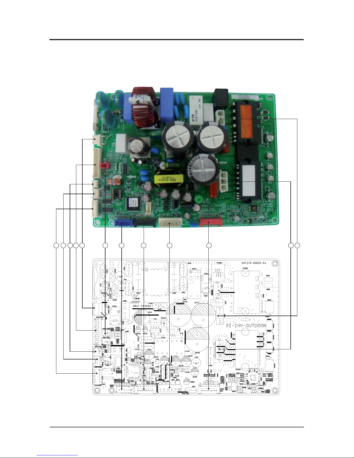
5-2-1 Main PCB
QAC018JXADCH
5 4 3 2 1 76 8 9 10 11 12
5-2 Outdoor Unit

PCB Diagram and Part List
5-4 Samsung Electronics
①
#1-#3:AC220V
②
#1~#28:SIGNALTOSUBPCB
③
#1~#2:OLPTHERMISTOR
④
#1:DC12V
#2:RXD
#3:TXD
#4:GND
⑤
#1~#5:EEVSIGNAL
#6:DC12V
⑥
#1:COM1(F1)
#2:COM2(F2)
⑦
#1~#2:OUTDOORTHERMISTOR
#3~#4:DISCHARGETHERMISTOR
#5~#6:CONDTHERMISTOR
⑧
#1~#10:Download
⑨
#1:DV310V
#3:GND
#4:DC15V
#5:FANPWM
#6:FANFeedback
⑩
#1~#10:Download
⑪
#1:COMPU-Phase
#2:COMPV-Phase
#3:COMPW-Phase
⑫
#1~#2:Reactor
CN030 : 4WAY VALVE
CN951 : SIGNAL TO SUB PCB
CN252 : THERMISTOR
CN851:S-NET Communication
CN701 : EEV
CN901 : BLDC MOTOR
CN302:Communication(COM1)
CN551: Downloader
CN251 : THERMISTOR
CN451 : COMP POWER
CN201 : Downloader
CN051 : Reactor

PCB Diagram and Part List
Samsung Electronics 5-5
5-2-2 SUB PCB
Q
AC018JXADCH
1 2
①
#1:DC12V
#2:GND
②
#1~#28:SIGNALTOMAINPCB
CN12 : DC12V
CN951 : SIGNAL TO MAIN PCB

PCB Diagram and Part List
5-6 Samsung Electronics
20 19 18 17 16 15 1314 12
11
10
9
8
765
1
2
3
4
No Part Code Local Function Description
1 3711-003404 CN703 BASE-HEATER YW396-03AV BLU
2 3711-003406 CN702 4WAY-1 YW396-03AV YEL
3 3711-003407 CN701 HOTGAS YW396-03AV RED
4 3711-000203 CN101 POWER YW396-03AV WHT
5 3711-002001 CN306 DOWNLOAD YDW200-20P BLK
6 3711-007817 CN806 EEPROM B7P-MQ WHT
7 3711-000024 CN501 MODE SELECTOR SMW250-03 WHT
8 DB65-00320A CN304 DRED DAPC-2009-6P BLK
9 3711-000744 CN103 EARTH YDW236-01 WHT
10 3711-000177 CN303 COMM-INDOOR YW396-02V RED
11 3716-001162 CN003 QUIET S/W BR-7623-2P BLK
12 3711-005096 CN302 COMM-OPTION SMW200-05 BLK
13 3711-007069 CN402 HIGH PRESSURE S/W B04B-XARK-1 RED
14 3711-007325 CN401 LOW PRESSURE S/W B04B-XARK-1 BLU
15 3711-001038 CN305 COMM INV SMW250-06 WHT
16 3711-000939 CN801 ERROR/COMP CHECK SMW250-04 RED
17 3711-000176 CN12 DC12V YW396-02V BLU
18 3711-000997 CN803 EEV1 SMW250-05 BLU
19 3711-001036 CN802 EEV4 SMW250-06 BLU
20 3711-001084 CN403 OUT TEMP/COND/DISQ/OLP SMW250-08 WHT
5-2-3 MAIN PCB
QAC024JXADCH, AC030JXADCH, AC036JXADCH, AC042JXADCH, AC048JXADCH,
AC054KXADCH

PCB Diagram and Part List
Samsung Electronics 5-7
①
#Reactor-A2:WHT
#Reactor-B2:WHT
②
#Reactor-A2:BLK
#Reactor-B2:BLK
③
#1:RXD,#2:TXD
#3:GND,#4:DC5V
#5:DC12V,#6:INV.SMPSsignal
④
#1:RXDATARO,#2:TXDATARO
#3,#8:N.C,#4~#7:DATAsignal
#9:GND,#10:DC5V
⑤
ForS/Wengineerdebugging
⑥
#1:DC360V
#2:N.C
#3:GND
#4:DC15V
#5:FANRPM
#6:FANRPMfeedback
⑦
#1:DC360V
#2:N.C
#3:GND
#4:DC15V
#5:FANRPM
#6:FANRPMfeedback
⑧
#1:COMP.U-phase(RED)
#2:COMP.V-phase(BLU)
#3:COMP.U-phase(YEL)
Reactor-A1/B1 Reactor-A2/B2
CN50(2PIN/RED)-Communication
CN22-Downloader
CN21-DAC/ENCODER
CN91-FAN2
CN90-FAN1 CN71-COMP.
2
3 465 8
7
1
QAC024JXADCH, AC030JXADCH, AC036JXADCH, AC042JXADCH, AC048JXADCH
5-2-4 INVERTER PCB

PCB Diagram and Part List
5-8 Samsung Electronics
QAC054KXADCH
①
#Reactor-A1 : WHT
#Reactor-B1 : WHT
②
#Reactor-A2 : BLK
#Reactor-B2 : BLK
③
#1 : RXD
#2 : TXD
#3 : GND
#4 : DV5V
#5 : DV12V
#6 : INV, SMPS SIGNAL
④
#1 : RXD_INV
#2 : TXD_INV
#3 : BOOT_INV
#4 : TDO_INV
#5 : TCK_INV
#6 : TDI_INV
#7 : TMS_INV
#8 : nTRST
#9 : GND
#10~#11: 5V
#14 #18 #19 : ENC
#17 : GND
#20 : SUB
⑤
#1 : DC310V #2 : N.C
#3 : GND
#4 : DV15V
#5 : FAN RPM #6 : FAN RPM
Feedback
⑥
#1 : DC310V #2 : N.C
#3 : GND
#4 : DV15V
#5 : FAN RPM #6 : FAN RPM
Feedback
⑦
#1 : Compressor U-phase(RED)
#2 : Compressor V-phase(BLU)
#3 : Compressor W-phase(YEL)
⑧
#1 : L-Phase/BRN
#2 :N-Phase/SKY
Reactor-A1/B1 Reactor-A2/B2 CN351 - Main COMM CN551 – Downloader
CN901 – FAN1
CN911 – FAN2
CN401 – Compressor L, N- 220V Power
8 2
1 4 3 7 6 5
PCB Diagram and Part List
Samsung Electronics 5-9
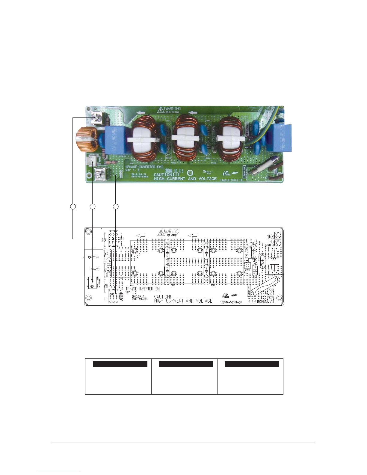
QAC024JXADCH, AC030JXADCH, AC036JXADCH, AC042JXADCH, AC048JXADCH, AC054KXADCH
①
L1:BRN
②
N1:SKY-BLU
③
#1-#3:AC220~240V
L1-AC POWER L phase N1-AC POWER N phase CN01-AC POWER
3 1
2
5-2-5 EMI PCB

Samsung Electronics 6-1
6. Wiring Diagram
6-1 Indoor Unit
- AC018KNZDCH / AC024KNZDCH / AC030KNZDCH / AC036KNZDCH / AC042KNZDCH /
AC048KNZDCH / AC054KNZDCH
This Document can not be used without Samsung’s authorization.
24 VAC
CTBM
L1
L2
GND
240 VAC
WHT
WHT
BLK
GRN
G
BLK
LADDER DIAGRAM
SCHEMATIC DIAGRAM
NO HEAT - 61CC0564D
Wire Colors
BLK - BLACK
BLU - BLUE
BRN - BROWN
ORN - ORANGE
YEL - YELLOW
WHT - WHITE
GRN - GREEN
SFSR COIL
240 VAC
24 VAC
TR
1
2
3
4
5
6
BMFP
3 Amp
Fuse
3 Amp
Fuse
BLK
TR
GGS
WHT
GND
GGS
S
AM
S
UNG
HEATING PRODUCTS
230
PRP
1
C
V1
V2
F3
F4
BLK- L1
WHT - L2
BLU - C
EVA IN
LFSR
6
8
RED
6 8
MFSR
ST3 COIL
C
BRN
C
6
5
ST1 COIL
3
L1
L2
GND
G
BLK
GRN
WHT
NO HEAT
BLK
BLK
BLK
BLK
BLK
8
ORN
LEGEND
TR - TRANSFORMER
BMFP - 9 PIN MOLEX BLOWER MOTOR PLUG ASSEMBLY
GND - GROUND CONNECTION
BMMP - 9 PIN MALE MOLEX BLOWER MOTOR PLUG
CTBM - CONSTANT TORQUE BLOWER MOTOR
GGS - GREEN GROUND SCREW
HFSR - HIGH FAN SPEED RELAY
MT - MOTOR TERMINAL
MFSR - MEDIUM FAN SPEED RELAY
LFSR - LOW SPEED TAP RELAY
LEGEND
WHT - L2
BLK - L1
HPF
BRN - R
BLU - C
ORN = PIN 1
BLK = PIN 2
HPF - 6 PIN HEATER FEMALE PLUG
FAN OUT
BLK
CNTRO BD
WHT
PNK
YEL - L2 - 230 VAC TO HC
RED - L1 - 230VAC TO HC
WHT = PIN 3
BLU = PIN 4
0
1
2
4
6
8
EVA OUT
Room IN
Sensor
Plate
"A" Coil
RED = PIN 5
ORN - DEFROST INDOOR BLOWER MOTOR HI SPEED TAP
ORN
ORN
ORN - ST5
ERROR
EXPLANATION
E101
E121
E122
E123
E162
E163
NO COMMUNICATION FOR 2 MINUTES
BETWEEN INDOOR AND OUTDOOR UNIT
ERROR ON ROOM TEMPERATURE
SENSOR OF INDOOR UNIT (SHORT OR
OPEN)
ERROR ON EVA IN TEMPERATURE
SENSOR OF INDOOR UNIT (SHORT OR
OPEN)
ERROR ON EVA OUT TEMPERATURE
SENSOR OF INDOOR UNIT (SHORT OR
OPEN)
EEPROM ERROR OF MICOM (PHYSICAL
PROBLEM OF PARTS/CIRCUIT)
INDOOR UNITS REMOTE CONTROLLER
OPTION INPUT IS INCORRECT OR
MISSING
F1
F2
1(L)
2(N)
RED
BLU
WHT
BLK
YEL
GRN
BRN
BLU
BRN
BLU
BLK
BLK
BLK
BLK
BLK
GRN
GRN
GRN
PRP
PRP
PRP
PRP
PRP
230
230
PNK
7
8
9
PNK
PNK
PNK
PNK
PNKGRN
GRN
GRN
PRP
PRP
PRP
BLU - C
BLU - C
BLU - C
BLU - C
BRN - R
BRN - R
BRN - R
BRN - R
BRN - R
BRN
BRN
BRN
BRN
RED JACKET
BLK
BLK
BLK
BLK
BLK
BLK
SFSR COIL
FAN OUT
BLK
CNTRO BD
WHT
PRP
SFSR COIL
FAN OUT
BLK
CNTRO BD
WHT
GRN
HFSR
MFSR
LFSR
ST5 COIL
HFSR
BRN
BRN
BRN
BRN
BRN
BRN
GRN
GND
GGS
GRN
BLK
BLK - L1
BLK - L1
BLK - L1
WHT
WHT - L2
WHT - L2
ST - BLOWER MOTOR SPEED TAP
1
2
3
4
5
C
L
G
N
BLOWER
MP
PIN NUMBER S
3
2 1
6
5 4
9
8 7
CT
MOTOR
ORN
PRP
PNK
GRN
GRN
WHT
BLK
BLU
MT
BMMP
Sensor
Sensor
PRP - PURPLE
PNK - PINK
EEV1
DISPLAY
IN/OUT/DIS/EVA
COM2
COM1
HOTCOIL
LOW
FAN OUT
POWER
DOWNLOAD
EXT-T
MED
HIGH
COMP/
ERROR
FUSE-CHK
DRAIN
DVM
SPI
TURBO
CN412
GND
GGS
BLK
BRN
BRN
BLK
BRN
VAC
VAC
VAC
PNK
GRN
PNK
GRN

6-2 Samsung Electronics
6-2 Outdoor Unit
- AC018JXADCH
This Document can not be used without Samsung’s authorization.

Samsung Electronics 6-3
- AC024JXADCH, AC030JXADCH, AC036JXADCH, AC042JXADCH, AC048JXADCH
This Document can not be used without Samsung’s authorization.

6-4 Samsung Electronics
- AC054KXADCH
This Document can not be used without Samsung’s authorization.

Samsung Electronics 7-1
7. Reference Sheet
7-1 Refrigerating Cycle Diagram
Indoor Unit Outdoor Unit
Heat
Exchanger
(Evaporator)
Heat
Exchanger
(Condenser)
Cooling
Gas leak check point
Liquid pipe
Gas pipe
Compressor
Accumulator
3-Way valve
Capillary
3-Way valve
Q CONDENSER
High temperature and high pressure gas state coolant discharged from the compressor is converted to a liquid state as it
is cooled down by the heat emission in the outdoor condenser unit, and sent to the evaporator.
Q COMPRESSOR
Low temperature and low pressure coolant is compressed and sent to the cycling system.
QEVAPORATOR
Liquid coolant sucked in through the capillary tubes cools down the room by absorbing the surrounding
heat as it evaporates (converting from liquid to gas). (Absorbing heat required for evaporation)
QSERVICE VALVE
You can open the valve by turning the need valve counterclockwise using hex wrench, and it is used for vacuum, gas
purging, coolant injection, coolant purging, and indoor-outdoor unit connection.
QACCUMULATOR
Accumulator prevents the flow of liquid-state coolant into the compressor. (Liquid-state coolant flowing into the compressor will overload the compressor.)

7-2 Samsung Electronics
Model Code
Product Type
AM DVM
AJ PMA
AC CAC (USD) / ASD
AE EHS
AN VTL
AK
PAK
(Packaged System)
AG CHR
Separator
S General Set (NASA)
N Indoor unit (NASA)
X Outdoor unit (NASA)
A General Set (Non-NASA)
B
Indoor unit (
Non-
NASA)
C
Outdoor unit (
Non-
NASA)
Feature
F FLAGSHIP
P PREMIUM
D DELUXE <- Basic
S STANDARD
L FLAGSHIP + TROPICAL
R PREMIUM + TROPICAL
T DELUXE + TROPICA <- Basic Model
N STANDARD + TROPICAL
Feature
Code Type Remark
1 1 WAY CST
CST
2 2 WAY CST
N MINI 4 WAY CST
4 4 WAY CST
H HSP DUCT
Duct
M MSP DUCT
L LSP DUCT
E FRESH AIR INTAKE DUCT
C CEILING
ETC
J CONSOLE
F Concealed Floor Mounting
G FLOOR MOUNTING
P FAC FAC/PAC
V RAC-A3050(EEV)
RAC
Q RAC-NEO FORTE(EEV)
T RAC-NEO FORTE
D RAC-Domestic
R RAC-MALDIVE
A RAC-A3050
7 RAC-Crystal
U AIR HANDIING UNIT
ASD
Z
AIR HANDLING UNIT WITH
FRESH
Y HYDRO UNIT (Wall mount)
EHS
B HYDRO UNIT (Standing)
X HYDRO UNIT (TANK Integrated)
W WATER TANK
K FLAT(CEILING TYPE)_VTL
VTL
S STAND(EXPOSURE TYPE)_VTL
Power
A A(115V, 60hz, 1Ф)
B B(220V, 60Hz, 1Ф)
C C(208~230V, 60Hz)
D D(200~220V, 50Hz)
E E(220~240V, 50Hz)
F F(208~230V, 60Hz, 3Ф)
G G(380~415V, 50Hz, 3Ф)
H H(380V, 60Hz, 3Ф)
J J(460V, 60Hz, 3Ф)
K K(220~240V, 50/60Hz, 1Ф)
M M(127V, 50Hz)
N N (380~415V, 50/60Hz, 3Ф)
Year
E 2012
F 2013
H 2014
J 2015
K 2016
L
2017
Buyer NameCapacity
Series
C
COOLING ONLY
R410a
H
HEAT PUMP
R
HEAT RECOVERY
D
COOLING ONLY
R22
E
HEAT PUMP
A
Cooling only
R134A
B
Heat Pump
N
N/A
HCH
0
H4H8H
K
H
N
H
Z
H
D
H
C
H
H
H
/
H
A
H
A
H
A
Capacity
1 BTU/H(*100)
2 CMH(*10)
3 HP(/10)
4 WATT(*100)
7-2 Index of Model Name
7-2-1 Indoor Unit
※
"/" can be removed from the buyer card if there are not enough digits.

Samsung Electronics 7-3
Model Code
7-2-2 Outdoor Unit
※
★
MCD: Dummy mock-up model
※
“/” can be removed from the buyer card if there are not enough digits.
Product Type
AM DVM
AJ PMA
AC CAC (USD) / ASD
AE EHS
AN VTL
AK
PAK
(Packaged System)
AG CHR
Separator
S General Set (NASA)
N Indoor unit (NASA)
X Outdoor unit (NASA)
A General Set (Non-NASA)
B
Indoor unit (
Non-
NASA)
C
Outdoor unit (
Non-
NASA)
Feature
F FLAGSHIP
P PREMIUM
D DELUXE <- Basic
S STANDARD
L FLAGSHIP + TROPICAL
R PREMIUM + TROPICAL
T DELUXE + TROPICA <- Basic Model
N STANDARD + TROPICAL
FEATURE
Code Type Remark
A Inv+Side+General Temp
CAC
S Inv+Side+Low Temp
Q Inv+Side+Tropical Temp
F Inv+Top+Tropical Temp
B Non Inv+Side+General Temp
N Non Inv+Side+Low Temp
R Non Inv+Side+Tropical Temp
ࣜ
Non Inv+Top+Tropical Temp
4Way : 4, MSP Duct : M, Ceiling : C
Power
A A(115V, 60hz, 1Ф)
B B(220V, 60Hz, 1Ф)
C C(208~230V, 60Hz)
D D(200~220V, 50Hz)
E E(220~240V, 50Hz)
F F(208~230V, 60Hz, 3Ф)
G G(380~415V, 50Hz, 3Ф)
H H(380V, 60Hz, 3Ф)
J J(460V, 60Hz, 3Ф)
K K(220~240V, 50/60Hz, 1Ф)
M M(127V, 50Hz)
N N (380~415V, 50/60Hz, 3Ф)
Year
E 2012
F 2013
H 2014
J 2015
K 2016
L
2017
Buyer NameCapacity
Series
C
COOLING ONLY
R410a
H
HEAT PUMP
R
HEAT RECOVERY
D
COOLING ONLY
R22
E
HEAT PUMP
A
Cooling only
R134A
B
Heat Pump
N
N/A
HCH
0
H5H4H
K
H
X
H
A
H
D
H
C
H
H
H
/
H
A
H
A
H
A
Capacity
1 BTU/H(*100)
2 CMH(*10)
3 HP(/10)
4 WATT(*100)

This Service Manual is a property of Samsung Electronics Co., Ltd.
Any unauthorized use of Manual can be punished under applicable
International and/or domestic law.
© Samsung Electronics Co., Ltd. March. 2016.
Printed in Korea.
Code No. AC-00154E_1
GSPN (GLOBAL SERVICE PARTNER NETWORK)
Area Web Site
Europe, CIS, Mideast & Africa gspn1.samsungcsportal.com
Asia gspn2.samsungcsportal.com
North & Latin America gspn3.samsungcsportal.com
China china.samsungportal.com
 Loading...