

AIR CONDITIONER
CONTENTS
FLOOR STAND TYPE AIR CONDITIONER
Basic : AF55JV1MAEE
CCPQXK840CA / CCPPNK840CA : ledoM
AC036KNPPCC / AC036KXQPCC
AC140KNPDEH / AC140KXADGH
AC100KNPDEH / AC100KXADEH
AC048KNPDEC / AC048KXADGC
AC036KNPDEC / AC036KXADEC
Model Code : AC048KNPPCC/MG AC048KXQPCC/MG
AC036KNPPCC/MG AC036KXQPCC/MG
AC140KNPDEH/EU AC140KXADGH/EU
AC100KNPDEH/EU AC100KXADEH/EU
AC048KNPDEC/TL AC048KXADGC/TL
AC036KNPDEC/TL AC036KXADEC/TL
1. Precautions
2. Product Specications
3. Disassembly and Reassembly
4. Troubleshooting
5. PCB Diagram
6. Wiring Diagram
7. Reference Sheet
AC048KXQPCC
AC036KXQPCC
AC140KXADGH
AC048KXADGC
AC048KNPDEC/SV AC048KXADGC/SV
AC048KNPPCC
AC036KNPPCC
AC140KNPDEH
AC100KNPDEH
AC048KNPDEC
AC036KNPDEC
AC100KXADEH
AC036KXADEC

Contents
1. Precautions ······································································································································· 1-1
1-1 Precautions for the Service ············································································································ 1-1
1-2 Precautions for the Static Electricity and PL ··············································································· 1-1
1-3 Precautions for the Safety ·············································································································· 1-1
1-4 Others ················································································································································ 1-1
2. Product Specifications ·············································································································· 2-1
2-1 The Feature of Product ··················································································································· 2-1
2-1-1 Features ·································································································································· 2-1
2-1-2 Changes in comparison to basic model ············································································ 2-2
2-2 The Comparative Specifications of Product ················································································ 2-3
2-3 Accessory and Option Specifications ··························································································· 2-5
2-3-1 Filter·········································································································································· 2-5
2-3-2 Accessory ································································································································· 2-5
3. Disassembly and Reassembly ······························································································ 3-1
3-1 Indoor Unit ······································································································································· 3-2
3-2 Outdoor Unit ···································································································································· 3-10
4. Troubleshooting ···························································································································· 4-1
4-1 Indoor Display Error and Check Method ····················································································· 4-1
4-1-1 Indoor unit LED display at error detecting ······································································· 4-1
4-2 Outdoor Trouble shooting ············································································································· 4-2
4-3 Troubleshooting by symptoms ····································································································· 4-5
4-3-1 Communication error after finishing tracking (E202) ······························································ 4-5
4-3-2 Outdoor's service valve(Clog) ············································································································ 4-6
4-3-3 No Power(completely dead) - Initial diagnosis ································································· 4-7
4-3-4 E102 : Communication error between indoor and outdoor unit
E201 : Unit quantity miss matching beween Indoor and Outdoor
E202 : Abnormal state, no communication between Indoor and Outdoor Main PCB
E203 : 1min Time out of communication error(MainļInverter) ········································· 4-11
4-3-5 External Sensor Error (Error Code: E221, E231, E251, E320) ·················································· 4-12
4-3-6 E403 : Freezing control causes comp. down ··············································································· 4-13
4-3-7 E416 : Dischage temperature sensor error ··················································································· 4-14
4-3-8 E440, E441 : Abnormal outside temperature halts operation of the compressor ······· 4-15
4-3-9 Outdoor unit BLDC Fan1 or Fan2 error (E458 : Fan1 error, E475 : Fan2 error) ··············· 4-16

Contents
4-3-10 E461: Compressor start error
E467: Compressor wire missing error ·························································································· 4-17
4-3-11 E462 : Current protection control causes comp. down
E484 : PFC overload error ·················································································································· 4-18
4-3-12 E463 : OLP protection control caused comp. down ······························································ 4-19
4-3-13 E464 : O.C. (Over Current) error······································································································· 4-20
4-3-14 E466: DC Link Over voltage/ Low voltage error······································································· 4-21
4-3-15 Pipe Blocking Error (Error Code: E422) ························································································ 4-22
4-3-16 The others ················································································································································ 4-23
4-3-17 Setting an indoor unit installation option ················································································· 4-24
5. PCB Diagram ··································································································································· 5-1
5-1 Indoor unit ········································································································································ 5-1
5-1-1 Main PCB ································································································································ 5-1
5-1-2 Power PCB ······························································································································ 5-3
5-1-3 Panel PCB ································································································································ 5-4
5-2 Outdoor unit ···································································································································· 5-5
5-2-1 Main PCB Diagram ················································································································ 5-5
5-2-2 Inverter PCB ··························································································································· 5-6
5-2-3 EMI PCB ··································································································································· 5-10
6. Wiring Diagram ····························································································································· 6-1
6-1 Indoor unit ········································································································································ 6-1
6-2 Outdoor unit ···································································································································· 6-2
7. Reference Sheet ···························································································································· 7-1
7-1 Index for Model Name ···················································································································· 7-1
7-2 Refrigerating Cycle Diagram ·········································································································· 7-2

Samsung Electronics 1-1
1. Precautions
1-1 Precautions for the Service
O Use the standard parts when replacing the electric parts.
– Confirm the model name, rated voltage, rated current of the electric parts.
O Repair the disconnection of HARNESS securely when repairing the break down.
– If there is any connection error, it causes an abnormal noise and incorrect operation.
O In case that you assemble or disassemble the products with laying it on the side, do work on the work cloth.
– If not, the exterior of products can be scratched.
O
Remove dust and foreign materials from harness, connection part, and inspection part thoroughly when repairing the break down.
– It protects the danger of fire such as tracking and short.
O Tighten tightly the service valve of outdoor unit and the cap of charging valve with a monkey spanner.
O Check the assembly status of parts after repairing the break down.
– It should be same as the status before repairing.
1-2 Precautions for the Static Electricity and PL
O As the PCB power terminal has a weakness for the static electricity, pay attention to it during the repair and measurement.
– Work with insulation gloves during the repair and measurement of PCB.
O
Check the distance between the product and the other electronic appliances such as TV, video, and audio. It should be over 2m.
– If not, it causes a bad picture quality or a noise.
O Repairing the products by consumer should be strictly prohibited.
– There is a danger of electric shock or fire due to incorrect disassembly.
1-3 Precautions for the Safety
O Do not pull any electric wires and do not touch an auxiliary power switch with a wet hand.
– There is a danger of electric shock or fire.
O In case any wire or power plug has been damaged, replace it to eliminate any possible danger.
O Do not bend the power cord by force and do not put any heavy object on the power cord.
– There is a danger of electric shock or fire.
O Do not use multi socket.
– There is a danger of electric shock or fire.
O Ground the product if necessary.
– Be sure to ground the product if there is any danger of electric leakage due to water or moisture.
O Be sure to turn off the auxiliary power switch or pull out the power plug during replacement or repair of electric parts.
– There is a danger of electric shock.
O In case the product will not be in use for a long time, the battery of remote control should be kept separately.
– Leakage of inside fluid can cause break down of remote control.
1-4 Others
O Never store or load the air conditioner upside down or sideways to prevent the damage to the compressor.
O Young children or infirm persons should be always supervised when they use the air conditioner.
O Max current is measured according to IEC standard for safety.
O Current is measured according to ISO standard for energy efficiency.
O
When installing, make sure there is no leakage. When recovering the refrigerant, ground the compressor first before removing the
connection pipe. If the refrigerant pipe is not properly connected and the compressor works with the service valve open, the pipe
inhales the air and it makes the pressure inside of the refrigerant cycle abnormally high. It may cause explosion and injury.
O Pump Down Procedure (When removing the product)
- Turn on the air conditioner and select Cool mode to run the compressor for 3 minutes.
- Release the valve caps on High and Low pressure side.
- Use L wrench to close the valve on the high pressure side.
- Approximately 2 minutes after, close the valve on the low pressure side.
- Stop operation of the air conditioner.
- Disconnect the pipes.

Product Specifications
Samsung Electronics 2-1
2. Product Specifications
2-1 The Feature of Product
2-1-1 Features
O Strong Turbo/convenient long-distance operation
Quicker and more consistent air cooling/warming is guaranteed by turbo operation that provides strong
cooling/warming for 30 minutes or by long-distance operation that ensures cooling/warming even in places a
long way from the air conditioner.
O Stylish, high quality design
Neat and luxurious style boasts high-quality interior design that ts naturally into any place.
O Compact Remote Controller
A small hand-size remote control makes it even easier to use.
O Long Piping(Length & Height)
It can give the benet to the installers and aries the reliability of the air conditioner.
O Long Ambient Operation(In Low Temperature)
It can arise the reliability and the capacity of the air conditioner, especially operated in low temperature.
O Eco-friendly Product (Lead-Free, RoHS, WEEE)
O
High Performance & Energy Saving
With the advanced BLDC inverter technology, it makes a room cool with highly energy saving and arises the efficiency of air
conditioner.
Product Specifications
2-2 Samsung Electronics
Changed part Changed item and feature Basic After changed
Indoor Unit Wi-Fi Function added.
Outdoor Unit
(AC048KXQPCC
AC036KXQPCC
AC140KXADGH
AC048KXADGC)
Inverter controller changed.
Outdoor Unit
(AC100KXADEH
AC036KXADEC)
--
2-1-2 Changes in comparison to basic model
2-3 Samsung Electronics
Product Specifications
Samsung Electronics 2-4
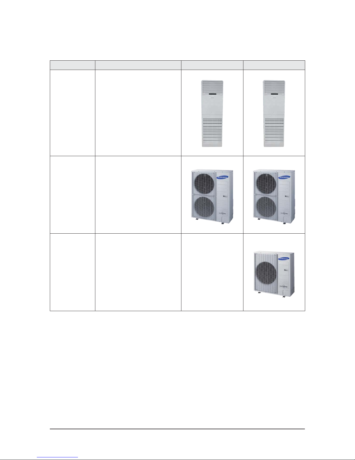
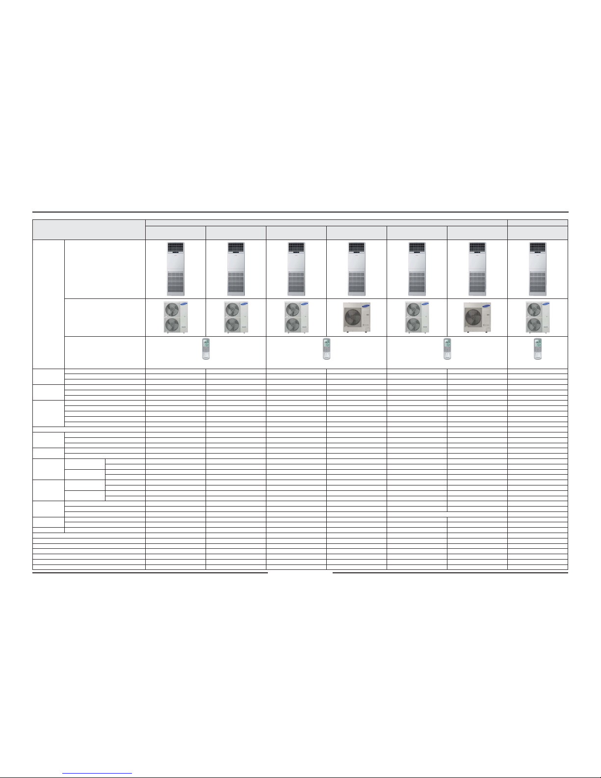
Item
Development Model Basic Model
AC048KNPPCC
AC048KXQPCC
AC036KNPPCC
AC036KXQPCC
AC140KNPDEH
AC140KXAPGH
AC100KNPDEH
AC100KXAPEH
AC048KNPDEC
AC048KXAPGC
AC036KNPDEC
AC036KXAPEC
AF55JV1MAEEN
AF55JV1MAEEX
Design
Indoor Unit
Outdoor Unit
Wireless Remote Controller
DB93-15883B DB93-15883B DB93-15883B DB93-14643X
Performance
Cooling (T1) [Btu/h or W] 15 000/48 000/60 000 12 300 / 36 000 / 45 700 4 200 / 13 400 / 16 700 3 500 / 10 000 / 12 300 3 600 / 14 000 / 16 700 3 400 / 10 000 / 13 000 15000/48000/60000
Cooling (T3) [Btu/h] 42 000 32 000 - - - - 42000
Heating [W] - - 4 000 / 15 500 / 20 000 4 200 / 11 200 / 14 000 - - -
Power Consump-
tion
Cooling (T1) [W] 890 / 4,050 / 6,600 1,100 / 3,030 / 4,000 900 / 4,320 / 5,900 1,100 / 3,700 / 4,900 820 / 5,040 / 5,600 880 / 3,270 / 4,900 890/3930/6600
Cooling (T3) [W] 4,920 3,700 - - - - 4950
Heating [W] - - 700 / 4,500 / 6,600 900 / 3,390 / 4,500 - - -
EER/COP
Cooling (T1) [Btu/h·W or W/W] 11.85 11.88 3.10 11.88 2.78 3.06 12.21
Cooling (T3) [Btu/h·W] 8.54 8.65 - 8.65 - - 8.48
Heating [W/W] - - 3.44 - - - -
SEER [W/W] - - - A+ (5.8) - - -
SCOP[ [W/W] - - - A+ (4.1) - - -
Voltage / Frequency 230V, 60Hz 3Φ 380-415V, 50Hz 220-240V, 50Hz 3Φ 380-415V, 50Hz 220-240V, 50Hz 230V, 60Hz
Operating Current
Cooling (T1) [A] 4.7 / 18.2 / 28.5 5.7 / 13.5 / 18.3 1.9 / 6.8 / 9.5 4.3 / 16.4 / 23.2 1.6 / 7.8 / 9.0 4.4 / 14.4 / 22.5 4.7/17.2/28.5
Cooling (T3) [A] 21.3 16.7 - - - - 21.1
Heating [A] - - 1.4 / 6.7 / 10.7 4.1 / 14.9 / 20.5 - - -
Noise
Indoor Unit [dBA] 51 / - 47 / - 51 / 51 47 / 47 51 / - 45 / - -
Outdoor Unit [dBA] 55 / - 51 / - 53 / 54 53 / 55 53 / - 51 / - -
Size
Net Dimension
(WxHxD)
Indoor Unit [mm] 610*1850*400 610*1850*400 610*1850*400 610*1850*400 610*1850*400 610*1850*400 610*1850*400
Outdoor Unit [mm] 940*1420*330 940*1210*330 940*1210*330 940*998*330 940*1210*330 940*998*330 940*1420*330
Shipping Dimension
(WxHxD)
Indoor Unit [mm] 705*1963*493 705*1963*493 705*1963*493 705*1963*493 705*1963*493 705*1963*493 705*1963*493
Outdoor Unit [mm] 995*1597*426 995*1388*426 995*1388*426 995*1096*426 995*1388*426 995*1096*426 995*1597*426
Weight
Net Dimension
Indoor Unit [kg] 46 46 46 42 46 42 46
Outdoor Unit [kg] 92 81 91 72 81 69 90
Shipping Dimension
Indoor Unit [kg] 52 52 52 49 52 49 51
Outdoor Unit [kg] 102 90 101 77 90 74 100
Harness
Specications
Indoor Fan Motor FMAF031SSA FMAF031SSA FMAF031SSA FMC9731SSC FMAF031SSA FMC9731SSC FMAF031SSA
Compressor UG5T450FXAJX UG5TK1450FJX UG5TK1450FJX UG8T300FUBJU UG5TK1450FJX UG8T300FUBJU UG5T450FXAJX
Outdoor Fan Motor DAO335130ZRD ATB125FGA DAO335130ZRD DAO335130ZRD DAO335130ZRD
Piping
High Pressure 3/8" 3/8" 3/8" 3/8" 3/8" 3/8" 3/8"
Low Pressure 3/4" 5/8" 5/8" 5/8" 5/8" 5/8" 3/4"
Exterior Display LED LED LED LED LED LED LED
Refrigerant Type R410A R410A R410A R410A R410A R410A R410A
Factory Charging [g] 2600 2400 3500 3000 2900 2400 2600
Additional Refrigerant (for every 1m) [g] 30 30 50 50 30 30 30
Basic Piping Length [m] 5 5 5 5 5 5 5
Max. Piping Length [m] 75 75 75 50 75 50 50
Max. Level Dierence [m] 30 30 30 30 30 30 30
Option Code 01146A-1900D7-278C00-370000 01146A-190096-276900-370000 01146A-1950C7-278C9B-370000 01146A-195085-276470-370000 01146A-1900C7-278C00-370000 01146A-190085-276400-370000 01144A-1900C7-279100-370010
2-2 The Comparative Specifications of Product
2-5 Samsung Electronics
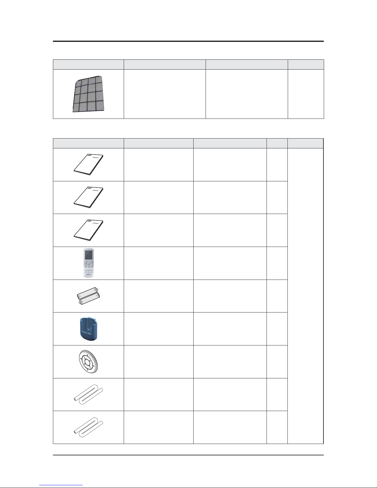
2-3-1 Filter
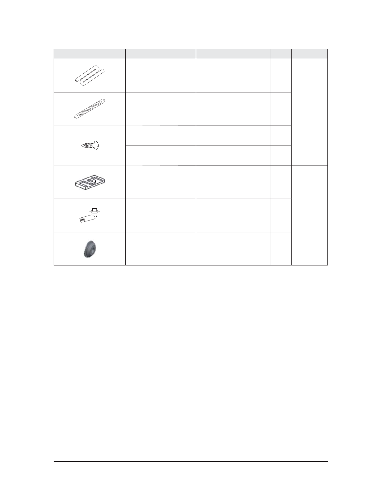
2-3-2 Accessory
2-3 Accessory and Option Specifications
Item Descriptions Code-No. Remark
Air Filter DB63-02928B
Basic/
Water Washing
Item Descriptions Code-No. Q'ty Remark
Manual
(AC048/036KNPPCC)
DB68-04872A 1
Indoor Unit
Manual
(AC140/100KNPDEH)
DB68-06271A
DB68-06272A
1
Manual
(AC048/036KNPDEC)
DB68-06270A 1
Wireless Remocon DB93-15883B 1
Battery DB47-90024A 2
Holder Remocon DB61-06087A 1
Rubber Cabi Hole DB73-00195A 1
Insulation Tube DB62-10944A 1
Insulation
(AC048/036KN*)
DB72-50300A 1
Product Specifications
Samsung Electronics 2-6
Item Descriptions Code-No. Q'ty Remark
Insulation
(AC140/100KN*)
DB72-50300C 1
Indoor Unit
Holder Top DB61-40042B 1
Screw (L14) 6002-000538 4
Screw (L12) 6002-000231 4
Rubber leg DB73-20134A 4
Outdoor Unit
Drain Plug DB67-00806A 1
CAP Drain DB63-10355C 3
Samsung Electronics 3-1
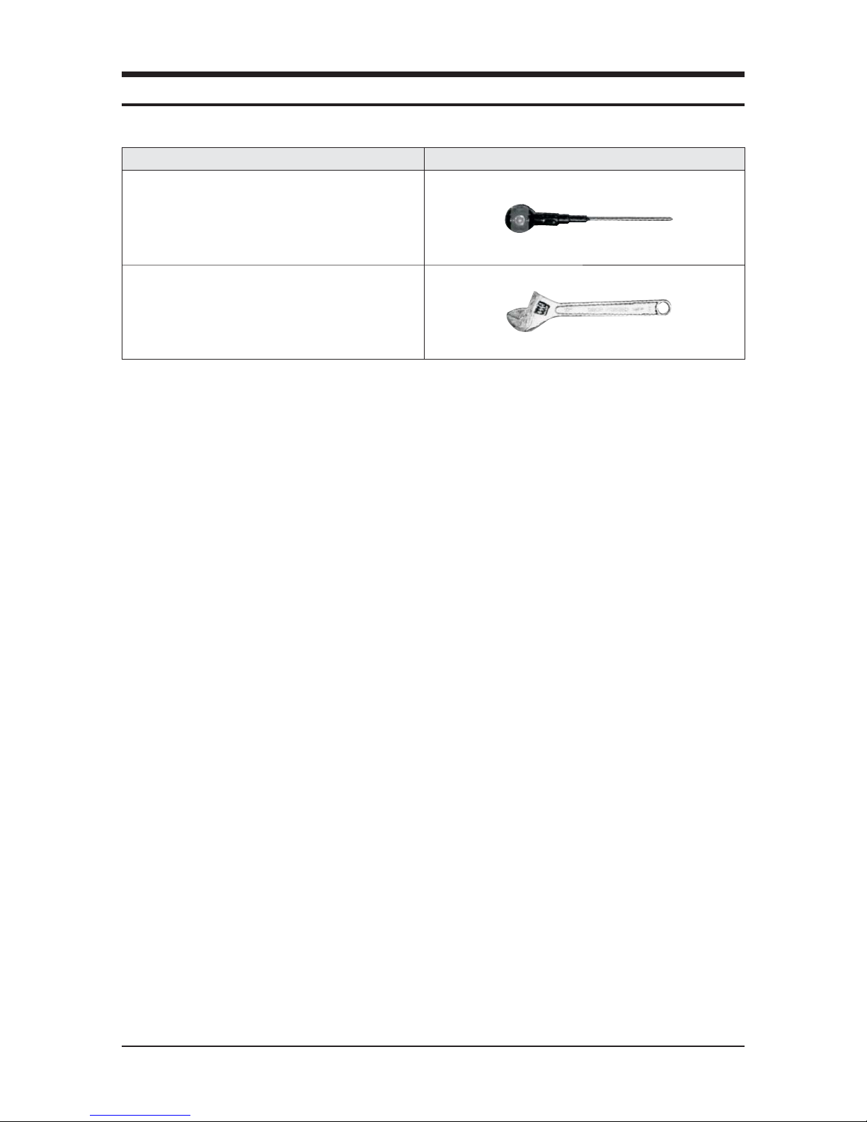
Item Remark
+Screw driver
Monkey spanner
QNecessary Tools
3. Disassembly and Reassembly
3-2 Samsung Electronics
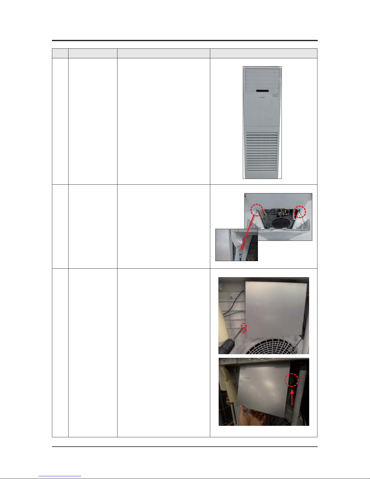
No Parts Procedure Remark
1 Indoor unit 1) Stop the operation of the air conditioner
and disconnect the main power supply.
2 Ass'y Inlet Part 1) Open the Ass'y Inlet and remove the
safety clips.
3 Ass'y Cover Control 1) Loosen one fixing screw of Ass'y Cover
Control. (Use +Screw driver) and detach
the cover.
2) Lift up the Ass'y Cover Control and detach
it by pulling the bottom outward.
3-1 Indoor Unit
Disassembly and Reassembly
Samsung Electronics 3-3
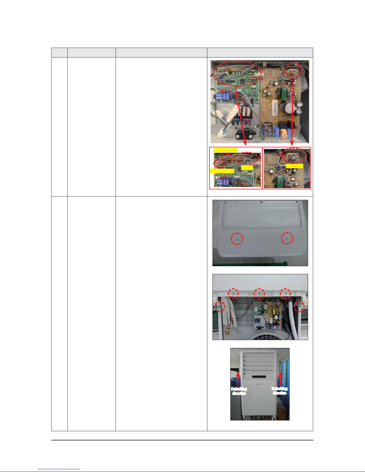
No Parts Procedure Remark
3) Detach the connectors connected to
Panel-Outlet and the Motor Connector.
Motor-In
Panel
Horizontal blade
Vertical blade
4 Ass'y Panel-outlet 1) Loosen the 7 fixing screws of
Ass'y Panel-Outlet and detach the
panel outlet by pushing upwards.
(Use +Screw driver)
Detaching
direction
Detaching
direction
Disassembly and Reassembly
3-4 Samsung Electronics
No Parts Procedure Remark
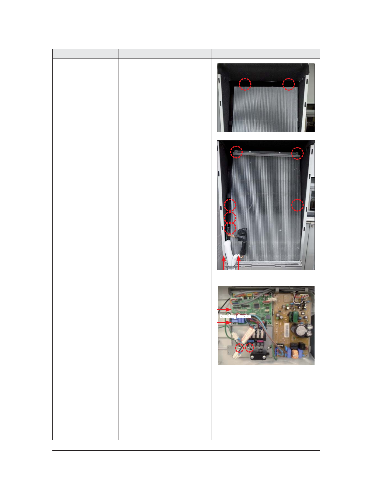
5 Ass’y Eva 1) Loosen the 2 fixing screws of Cover EVA
Top and detach the Top.
2) Loosen the 4 fixing screws of EVA.
3) Loosen the grounding screw.
4) Pull out the sensor cable.
5) Pull out the Bracket Pipe upward.
6) Pull the upper part of the Heat
Exchanger toward you and lift up the
Heat Exchanger to detach.
6 Ass'y Control In 1) Loosen the 1 fixing screw of Ass'y
Control.
2) Loosen the EVA grounding fixing screw.
3) Detach the Ass'y Control In by pushing
it to the right.
Detaching direction
❷
❶
Disassembly and Reassembly
Samsung Electronics 3-5
No Parts Procedure Remark
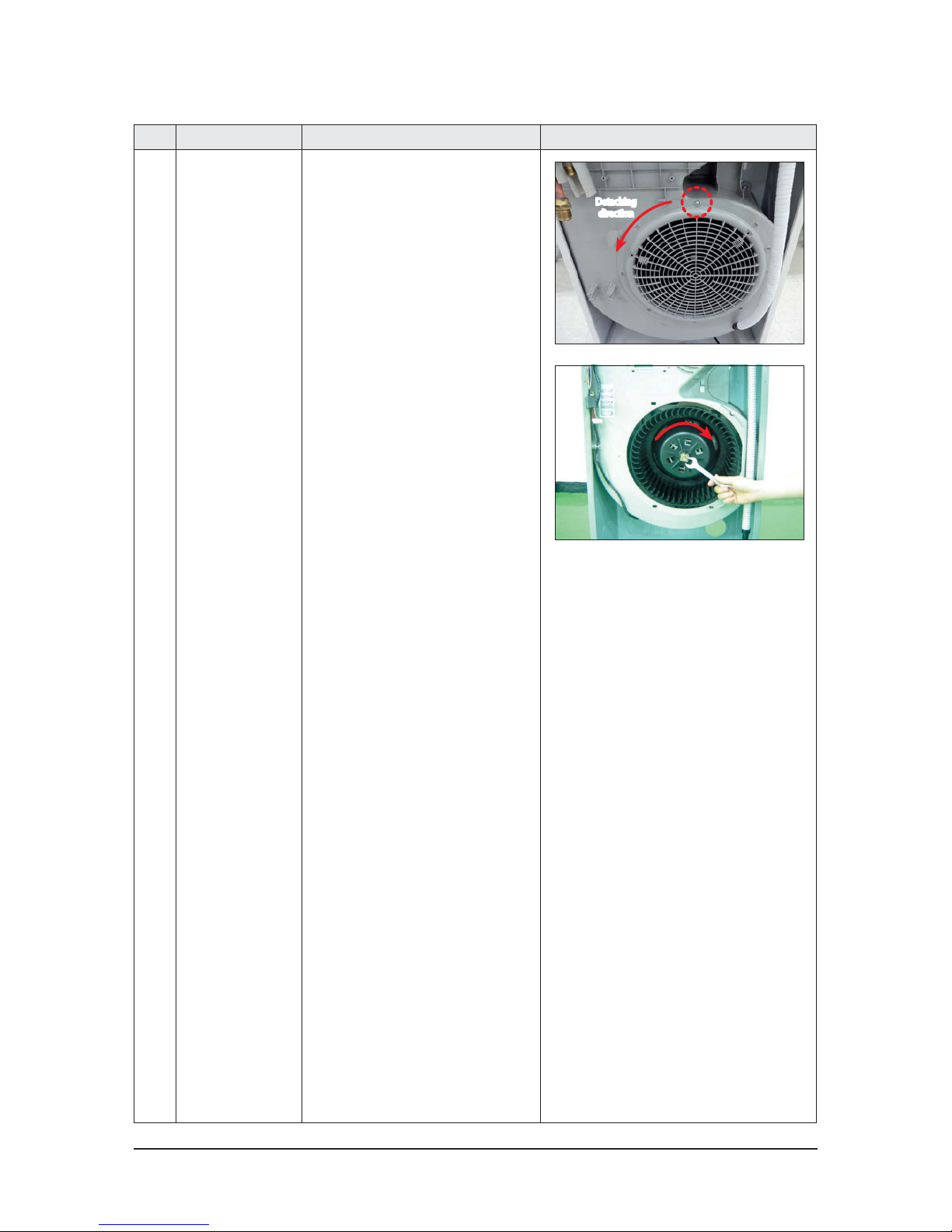
7 Ass’y Blower 1) Loosen the 1 fixing screw of Guard Fan.
(Use +Screw driver)
2) Push the Guard Fan in the arrow
direction and detach the guard.
3) Loosen the Blower nut clockwise and
pull the Blower toward you and detach
it. (Use a monkey spanner.)
Detaching
direction
Disassembly and Reassembly
3-6 Samsung Electronics
No Parts Procedure Remark
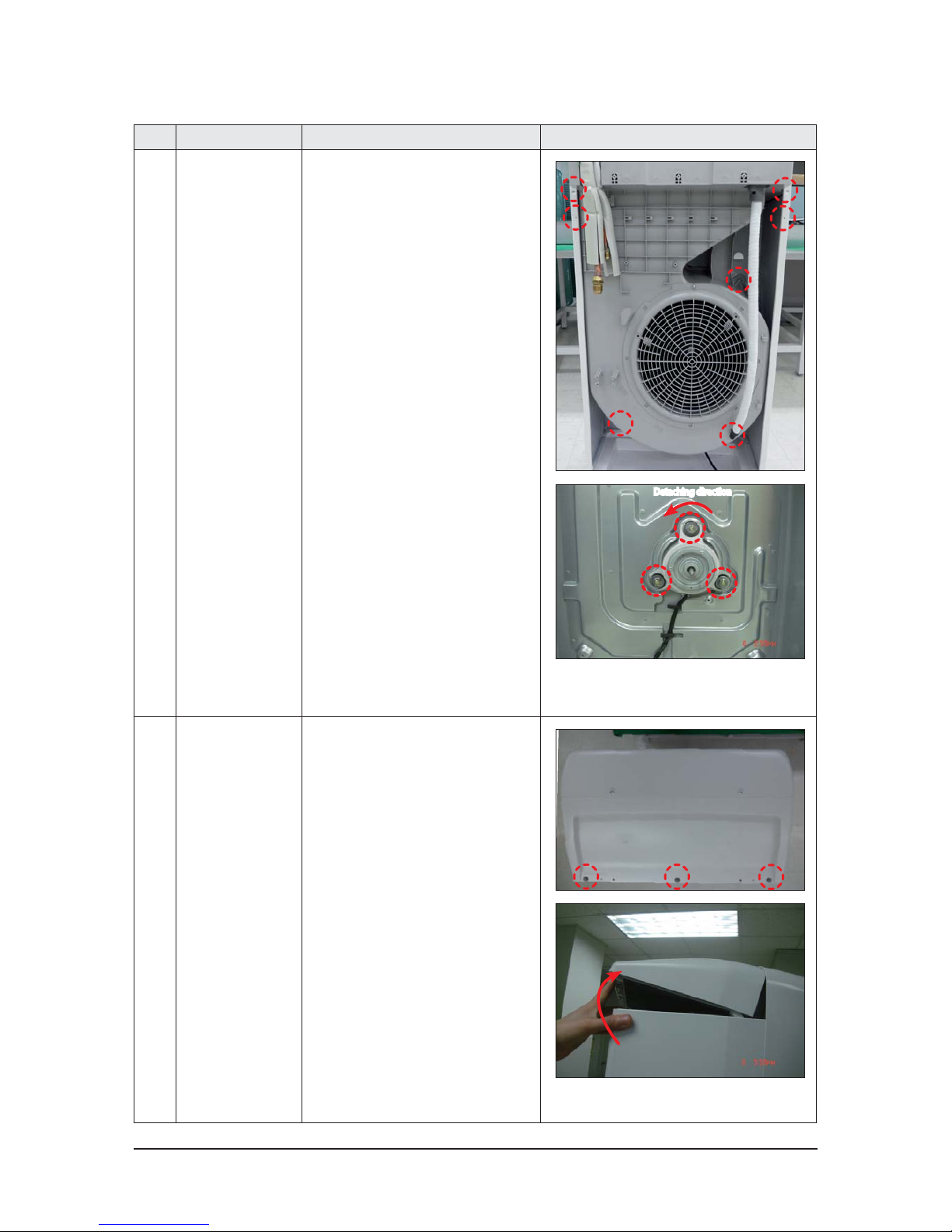
8 Ass’y Motor Blower 1) Loosen the 5 fixing screws of
Ass'y Duct Case and detach the case.
(Use +Screw driver)
2) Loosen the 3 fixing screws of
Motor and ground fixing screw.
(Use a monkey spanner.)
(Remove the connectors before
detaching the Motor.)
9 Cover Top 1) Loosen the 3 fixing screws of
Cover-Top and detach the cover.
(Use +Screw driver),
(Screw : TH type2 M4, L10, BLK)
2) Lift up the rear of Cover Top and
detach it.
Detaching direction
Disassembly and Reassembly
Samsung Electronics 3-7
No Parts Procedure Remark
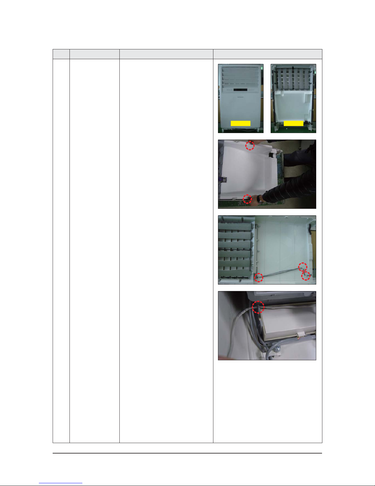
10 Ass'y Panel-Outlet
1) Panel-Outlet
2) As you push the 2 hooks on each side of
Panel outward, detach the bottom part
of Partition by lifting it toward you.
3) Detach the wire positioned with
Holder Wire.
4) Detach the wire positioned with
Holder Wire.
Rear sideFront side
Disassembly and Reassembly
3-8 Samsung Electronics
No Parts Procedure Remark
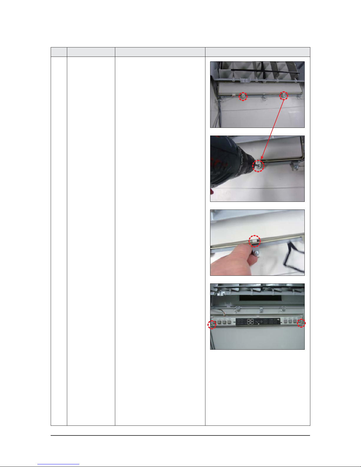
11 Ass'y Panel-outlet
- Seperate Display PBA
1) Loosen the 2 fixing screws of Case
Display PBA and detach the case.
(Use +Screw driver)
2) Unlink the fixing hook placed in the
middle of Case Display PBA.
3) Loosen the 2 fixing screws of PBA and
detach the PBA. (Use +Screw driver)
Disassembly and Reassembly
Samsung Electronics 3-9
No Parts Procedure Remark
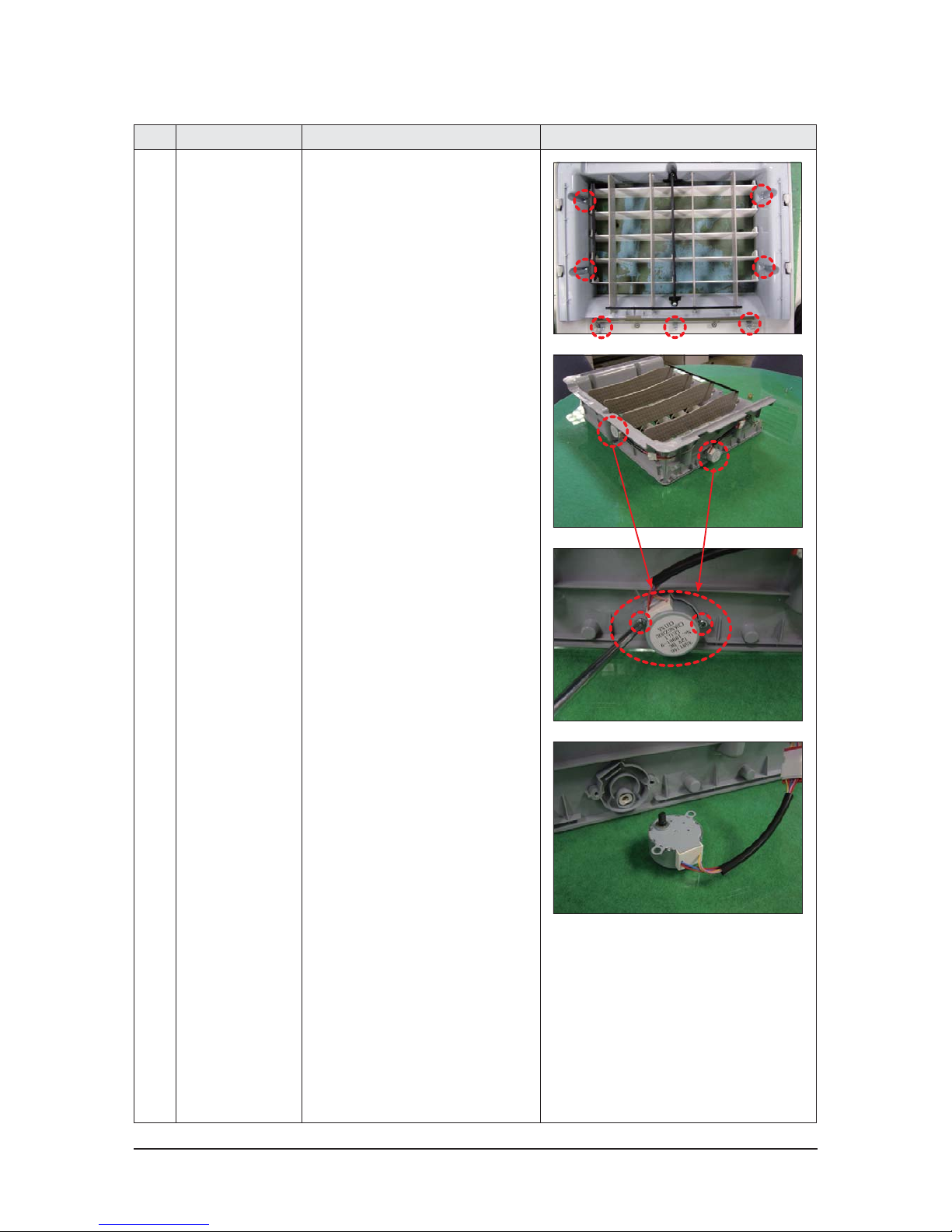
12 Ass'y Panel-outlet
- Motor Step
1) Loosen the 8 fixing screws of
Holder Blade and detach the holder.
(Use +Screw driver)
2) Loosen the 2 fixing screws of
Step Motor and detach the motor.
(Use +Screw driver)
3) The detached Step Motor.
3-10 Samsung Electronics
3-2 Outdoor Unit
No Parts Procedure Remark
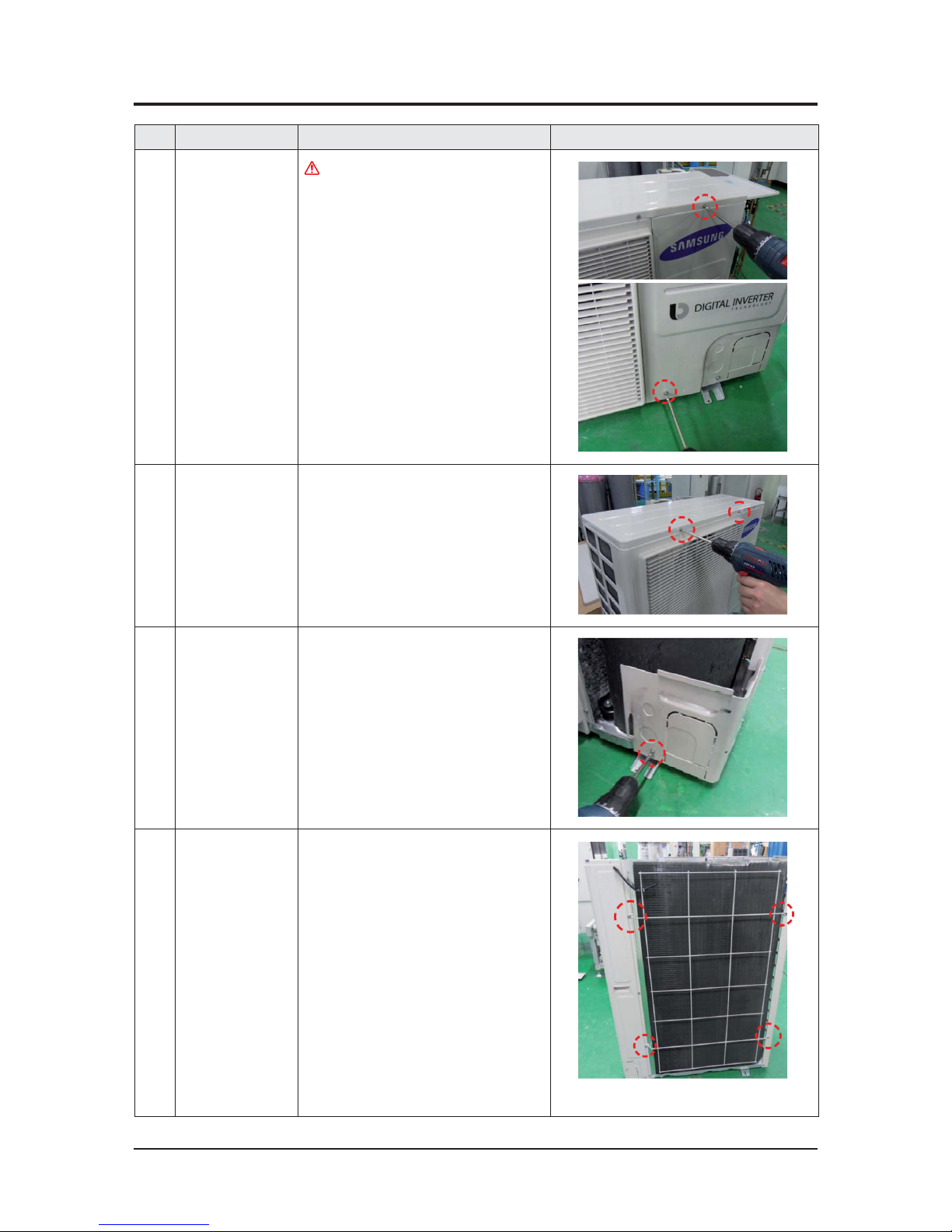
1 Cabi Front RH
You must turn off the Power before
disassembly.
1) Unscrew and remove two mounting
screw in the Cabinet Front RH.
(Use +Screw Driver)
2 Cabi Top
1) Unscrew and remove 9 screws
on each side of the Cabinet-Top.
(Use +Screw Driver)
3 Cabi Install Front
1) Unscrew and remove 1 screw
in the Cabinet-Install Front.
(Use +Screw Driver)
4 Guard Cond
1) Pull the sensor from Guard Cond.
2) Unscrew and remove 4 screws
in the Guard Cond.
(Use +Screw Driver)
Disassembly and Reassembly
Samsung Electronics 3-11
No Parts Procedure Remark
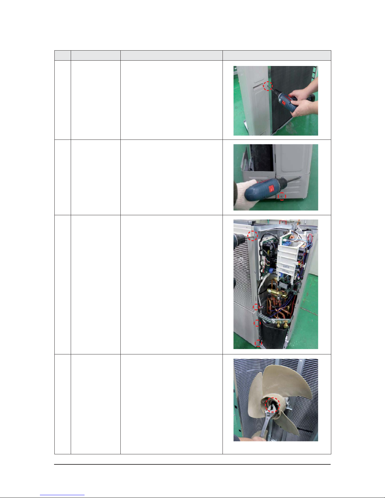
5 Cabi Back RH
1) Pull the sensor from Cabi Back RH.
2) Unscrew and remove 4 screws
on each side of the Cabinet Back RH.
(Use +Screw Driver)
6 Cabi Install Back
1) Unscrew and remove 1 screw
in the Cabinet-Install Back.
(Use +Screw Driver)
7 Cabi Front LF
1) Unscrew and remove 10 screws
in the Cabinet-Front LF.
(Use +Screw Driver)
8 Fan
1) Turn 2 mounting nuts as shown in
the picture and remove it.
(Use Adjustable Wrench)

Disassembly and Reassembly
3-12 Samsung Electronics
No Parts Procedure Remark
9 Motor
1) Separate the Fan Propeller.
2) Unscrew and remove the 8 Motor
mounting
screws. (Use +Screw Driver)
3) Disconnect the Motor wire From
Ass'y Control Out.
10 Bracket Motor
1) Unscrew and remove 2 mounting
screws in Bracket Motor.
(Use +Screw Driver)
11 Control Out
1) Disconnect 4 Connecters From
Ass'y Control Out.
2) Unscrew and remove 1 mounting
screw in Control Out.
(Use +Screw Driver)
3) Separate Ass'y Control Out.

Disassembly and Reassembly
Samsung Electronics 3-13
No Parts Procedure Remark
12 Assy 4way Valve
1) Purge the Coolant first.
2) Unscrew and remove 2 mounting
screws in Service Valve. (Use +Screw
Driver)
3) Separate the pipe from the
Entrance/Exit using a welder.
When removing the compressor, Heat Exchanger, and Pipe,
purge the Coolant inside the
Compressor completely and
remove the pipe with a welding
flame.
13 Assy EEV Valve
1) Unscrew and remove 2 mounting
screws in Service Valve.
(Use +Screw Driver)
2) Separate the pipe from the Entrance/
Exit using a welder.

Samsung Electronics 4-1
4. Troubleshooting
4-1 Indoor Display Error and Check Method
4-1-1 Indoor unit LED display at error detecting
- Thins to check before diagnosis
Display Explanation Check list
Product operation
Diagnosis
Method
Indoor
FAN
Outdoor
FAN
COMP
Indoor and Outdoor unit
communication Error
● Check the connection wire.
● Change the Main PCB.
Operation
OFF
Operation
OFF
Operation
OFF
Indoor unit room
temperature sensor
SHORT/OPEN
● Change the temperature sensor.
(Wire type)
Operation
OFF
Operation
OFF
Operation
OFF
Indoor unit Eva_in sensor
SHORT/OPEN
● Change the temperature sensor.
(Wire type)
Operation
OFF
Operation
OFF
Operation
OFF
Indoor unit
Fan motor Error
● Check the connection wire.
● Change the Fan motor.
● Change the Main PCB.
※ BLDC Motor is used as Fan Motor,
therefore if you connect or disconnect
the connector while the power is still
on, it may get damaged. Make sure to
turn off the power before performing
any operation.
Operation
OFF
Operation
OFF
Operation
OFF
EEPROM ERROR
● Change PCB.
Operation
OFF
Operation
OFF
Operation
OFF
EEPROM Option
Setting Error
● Input option.
- Cannot input KEY
Operation
OFF
Operation
OFF
Operation
OFF
Thermal Fuse Error
(TERMINAL BLOCK)
● Check the connection wire.
Operation
OFF
Operation
OFF
Operation
OFF
Duplicated address
setting error
● Check address setting of Indoor units.
Operation
OFF
Operation
OFF
Operation
OFF
No response error of
address from indoor unit
● Check indoor unit's quantity setting
in outdoor unit.
● Check electrical connection and set-
ting.
Operation
OFF
Operation
OFF
Operation
OFF

Troubleshooting
4-2 Samsung Electronics
4-2 Outdoor Trouble shooting
The table below give indication about self diagnostic routine. Some of error code requires activities exclusively
for Authorized Service Center.
Outdoor unit
If an error occurs during the operation, it is displayed on the outdoor unit PCB LED, both MAIN PCB and
INVERTER PCB.
No. Error Code Meaning Remarks
1 E108
Error due to repeated address setting(when 2 or more devices has
same address within the network)
Check on repeated indoor unit main address
2 E121 Error on indoor temperature sensor of indoor unit(Short or Open) Indoor unit Room Thermistor Open/Short
3 E122 Error on EVA IN sensor of indoor unit(Short or Open) Indoor unit EVA_IN Thermistor Open/Short
4 E123 Error on EVA OUT sensor of indoor unit(Short or Open) Indoor unit EVA_OUT Thermistor Open/Short
5 E153 Error on float switch (2nd detection)
"Indoor unit Float Switch Open/Short Drain Pump
operation Check"
6 E154 RPM feedback error of indoor unit Check on indoor unit indoor Fan operation
7 E162 Outdoor unit EEPROM Read/Write error (H/W) Check Outdoor EEPROM PBA
8 E163 Outdoor unit EEPROM Read/Write error (Option) Check Outdoor EEPROM Data
9 E198 Error on thermal fuse of indoor unit (Open)
Thermal Fuse Open Check of indoor unit Terminal
Block
10 E201
"Communication error between indoor and outdoor
unit(Installation number setting error repeated
indoor unit address,indoor unit communication cable error)"
Check indoor quantity setting in outdoor
11 E202
"Communication error between indoor and outdoor
unit(Communication error on all indoor unit,
outdoor unit communication cable error)"
Check electrical connection and setting between
indoor unit and outdoor unit
12 E205
Communication error on all PBA within the outdoor unit
C-Box,communication cable error
-
13 E206
E206-C002 : Fan PBA communication error, E206-C003 : INV PBA
communication error
-
14 E221 Error on outdoor temperature sensor (Short or Open) Check Outdoor sensor Open / Short
15 E231 Error on outdoor COND OUT sensor (Short or Open) Check Cond-Out sensor Open / Short
16 E251
Error on discharge temperature sensor of compressor 1 (Short or
Open)
Check Discharge sensor Open / Short
17 E320 Error on OLP sensor (Short or Open) Check OLP sensor Open / Short
18 E346 Error due to operation failure of Fan2 FAN2 error
19 E347 Motor wire of Fan2 is not connected FAN2 error
20 E348 Lock error on Fan2 of outdoor unit FAN2 error
21 E353 Error due to overheated motor of outdoor unit's Fan2 FAN2 error
22 E355 Error due to overheated IPM of Fan2 FAN2 error
23 E378 Error due to overcurrent of Fan2 FAN2 error
24 E386 Over-voltage/low-voltage error of Fan2 FAN2 error
25 E387 Hall IC connection error of Fan2 FAN2 error
26 E389 V-limit error on Fan2 of compressor FAN2 error
27 E391 Error due to DataFlash of Fan2 FAN2 error
28 E393 Output current sensor error of Fan2 FAN2 error

Troubleshooting
Samsung Electronics 4-3
No. Error Code Meaning Remarks
29 E396 DC voltage sensor error of Fan2 FAN2 error
30 E399 Heat sink temperature sensor error of Fan2 FAN2 error
31 E403 Compressor down due to freeze protection control Check Outdoor Cond.
32 E404 System stop due to overload protection control Check Comp. when it start
33 E416 System stop due to discharge temperature
-
34 E422 Blockage detected on high pressure pipe
1. Check if the service valve is open
2. Check for refrigerant leakage(pipe connections,
heat exchanger) and charge refrigerant if
necessary
3. Check if there's any blockage on refrigerant
cycle(indoor unit/outdoor unit)
4. Check if additional refrigerant has been added
after pipe extension
35 E425 Reverse phase or open phase
Check whether 3 phase is reversed or opened.
36 E440 Heating mode restriction due to high air temperature
HEATING
37 E441 Cooling mode restriction due to low air temperature
COOLING
38 E446 Error due to operation failure of Fan1
FAN1 error
39 E447 Motor wire of Fan1 is not connected
FAN1 error
40 E448 Lock error on Fan1 of outdoor unit
FAN1 error
41 E452 Error due to ZCP detection circuit problem or power failure
-
42 E453 Error due to overheated motor of outdoor unit's Fan1
FAN1 error
43 E455 Error due to overheated IPM of Fan1
FAN1 error
44 E458 Fan speed error
FAN1 ERROR
45 E461 Error due to operation failure of inverter compressor
-
46 E462 System stop due to full current control
-
47 E463 Over current trip / PFC over current error
Check OLP sensor
48 E464 IPM Over Current(O.C)
IPM
49 E465 Comp. Over load error
-
50 E466 DC-Link voltage under/over error
Check AC Power and DC Link Voltage
51 E467
Error due to abnormal rotation of the compressor or unconnected
wire of compressor
Check Comp wire
52 E468 Error on current sensor (Short or Open)
Check Outdoor Inverter PBA.
53 E469 Error on DC-Link voltage sensor (Short or Open)
-
54 E471
Outdoor EEPROM checksum error between MAIN and INVERTER
(AC
777
KXAPNH)
Check Outdoor EEPROM PBA
55 E472 AC Line Zero Cross Signal out
-
56 E473 Comp Lock error
-
57 E474 Error on IPM Heat Sink sensor of inverter 1 (Short or Open)
heck Outdoor Inverter PBA
58 E475 Error on inverter fan 2
FAN2 ERROR
59 E478 Error due to overcurrent of Fan1
FAN1 error
60 E484 PFC Overload (Over current) Error
Check Outdoor Inverter PBA.
61 E485 Error on input current sensor of inverter 1 (Short or Open)
Check Outdoor EEPROM PBA
62 E486 Over-voltage/low-voltage error of Fan1
FAN1 error

Troubleshooting
4-4 Samsung Electronics
No. Error Code Meaning Remarks
63 E487 Hall IC connection error of Fan1
FAN1 error
64
E489 V-limit error on Fan1 of compressor
FAN1 error
65
E491 Error due to DataFlash of Fan1
FAN1 error
66
E493 Output current sensor error of Fan1
FAN1 error
67
E496 DC voltage sensor error of Fan1
FAN1 error
68
E499 Heat sink temperature sensor error of Fan1
FAN1 error
69
E500 IPM over heat error on inverter 1
Check Outdoor Inverter PBA.
70
E508 Smart install is not installed
-
71
E554 Gas leak detected
Check the refrigerant
72
E556
Error due to mismatching capacity of indoor and outdoor
unit
Check the indoor and Outdoor unit
Capacity
73
E557
Option code miss matching among the indoor units (only
for DPM)
Check the indoor option code
74
E590
Outdoor EEPROM checksum error between MAIN
and INVERTER (AC
777
JXAFKH, AC
777
JXAFNH,
AC
777
JXAPNH)
-
75
E660 Inverter Boot Code error
-

Troubleshooting
Samsung Electronics 4-5
4-3 Troubleshooting by symptoms
4-3-1 Communication error after finishing tracking (E202)
1. Check items
1) Is the communication cable short/open?
2) Is there a response from the indoor unit PCB?
2. Check procedure
No
Yes
Is there a response from the
indoor unit PCB?
No
Yes
In this case, is the
voltage waveform between the lines square
wave with amplitude over ±0.7V as shown
in the following picture?
+0.7V
-0.7V
Good
Bad
Check the communication cable and
replace the indoor unit PCB?
Remove the communication cable
connecting the outdoor unit to indoor unit,
and measure the signal on LINE 2 of the
outdoor unit with a scope
Reconnect the cable connecting
the outdoor unit to the indoor unit
and restart the unit.
If the communication still doesn’t work,
eht ecalper indoor unit PCB and
Check the communication
cable in each PCB
and replace the PCB
Yes
Is the power/communication
cable connected correctly?
No
Connect the power/communication
cable correctly.
outdoor unit PCB in order of mention.
cf.) If there is no oscillo scope, it can be replaced multimeter instead of osillo scope.

Troubleshooting
4-6 Samsung Electronics
4-3-2 Outdoor's service valve(Clog)
Wire remote controller display
E422
Symptom
Clogging of outdoor's service valve
Failure
Valve clog
NoNo
Yes Yes
Is the outdoor service
valve clogged?
Was lacking in refrigerant?
Check the normal of EVA-IN
TEMP SENSOR.
Open the outdoor's service valve Refrigerant Charge.

Troubleshooting
Samsung Electronics 4-7
4-3-3 No Power(completely dead) - Initial diagnosis
Outdoor unit is not powered on – Initial diagnosis (1phase)
1. Check items
1) Is the power supply voltage 220V?
2) Is the AC power connected correctly?
3) Are the LEDs in the main PCB and inverter PCB of the outdoor unit ON?
4) Is the input power voltage of the indoor unit 220V?
5) Is the wired remote controller connected correctly?
2. Check procedure
Yes
Turn off the main power switch
(circuit break of power outlet) and turn on
again after 30 seconds.
Check the input power
No
Is the outdoor unit power
supply (L-N) 220V?
Yes
Check the connection of the terminal block
No
Is the outdoor unit power
voltage (L-N) 220V?
Yes
Replace the inverter PBA
No
Is the voltage between
the terminal 2 (~) and 4 (~) of the
bridge diode 220V?
Yes
Replace the fuse
No
Is the fuse connected?
Yes
Replace the inverter PBA
No
Is the resistance value of R001 200?
Cont.

Troubleshooting
4-8 Samsung Electronics
Yes
Outdoor unit is not powered on – Initial diagnosis (1phase) (cont.)
Yes
Connect the reactor
No
Is the reactor connector
connected correctly?
Replace the PBA.
Cont.

Troubleshooting
Samsung Electronics 4-9
Cont.
Outdoor unit is not powered on – Initial diagnosis ( 3phase)
1. Check items:
1) Is the power supply voltage 380V?
2) Is the AC power connected correctly?
3) Are the LEDs in the main PCB and inverter PCB of the outdoor unit ON?
4) Is the input power voltage of the indoor unit 220V?
5) Is the wired remote controller connected correctly?
2. Troubleshooting procedure
No
No
No
No
No
Check the input power
Check connection of the outdoor unit
terminal block
Check the connection wires and
connectors of the indoor and outdoor units
Replace the PCB of the indoor unit if
the PCB (Transformer, fuse, pcd, etc.) fails
Replace the wired remote controller
Turn off the main power switch
(circuit break of power outlet) and turn on again
after 30 seconds.
Is the outdoor unit power
supply (N-R, N-S, N-T) 220Vac?
Is the outdoor unit power
voltage (L-N) 220Vac?
Is the indoor unit power supply
voltage (L-N) 220Vac?
Is the indoor unit power supply
voltage (V1-V2) 12Vdc?
Does the air conditioner
operate when pressing ON/OFF button of the
wired remote controller?

Troubleshooting
4-10 Samsung Electronics
Yes
Outdoor unit is not powered on – Initial diagnosis ( 3phase) (cont.)
Yes
Yes
Reconfigure the option DIP switches
Check the system depending
on the error display
No
No
Are the option DIP switches
inside the wired remote controller configured
correctly?
Is there an error
message displayed on the wired remote
controller display?
Check the target temperature
Cont.

Troubleshooting
Samsung Electronics 4-11
4-3-4 E102 : Communication error between indoor and outdoor unit
E201 : Unit quantity miss matching beween Indoor and Outdoor
E202 : Abnormal state, no communication between Indoor and Outdoor Main PCB
E203 : 1min Time out of communication error(MainļInverter)
1. Checklist :
1) Is the communication cable between the indoor unit and outdoor unit connected correctly?
2) Isn’t the power cable and communication cable wiring error?
2. Troubleshooting procedure
Yes
Restart after power off.
Is the communication error
occurred again?
Isn't the power cable and
communication cable wiring error?
Replace the outdoor unit PCB.
Terminate the service.
Correct the wrong wiring.
Is the connection of
communication cable normal?
Correct the connection of
communication cable.
Yes
Yes
No
No
No

Troubleshooting
4-12 Samsung Electronics
4-3-5 External Sensor Error (Error Code: E221, E231, E251, E320)
1. Test Item
1) Check the connection of the temperature sensor connector.
2) Check the resistance value of the temperature sensor.
2. Check procedure
Error Code Description
E221 Error of the temperature sensor of the outdoor unit
E231 Error of the COND. sensor of the outdoor unit
E251 Error of the discharge sensor of the outdoor unit
E320 Error of the OLP sensor of the outdoor unit
Power OFF
Is the temperature sensor connector
reconnected?
No
Yes
Yes
Replace the temperature sensor, ױ
Power ON. ױ
After confirming the state is normal, end the service.
No
Is the temperature
sensor-measuring resistance similar to the
table on the left?
After confirming the state is normal,
end the service.
No
Yes
Replace the outdoor unit PBA. ױ
Power is on. ױ After confirming the state is
normal, end the service.
(Example) COND. sensor/outdoor unit temperature sensor measuring resistance value by temperature: E231, E221
(Example) OLP sensor/discharge temperature sensor measuring resistance value by temperature: E320, E251.
Current temperature (°C)
Resistance
(KΩ)
Current temperature (°C)
Resistance
(KΩ)
70 4 20 10
60 5 10 20
50 6 0 30
40 7 -10 40
30 8
Current temperature (°C)
Resistance
(KΩ)
Current temperature (°C)
Resistance
(KΩ)
80 40 30 180
70 50 20 220
60 60 10 320
50 90 0 550
40 110
Is the temperature sensor connector
connected?
e.g.) Room temperature: 26ఁ
- Resistance: 10.28 KΩ
e.g.) Room temperature: 21ఁ
- Resistance: 205.4 KΩ
Does the same error occur again
after power is on?

Troubleshooting
Samsung Electronics 4-13
4-3-6 E403 : Freezing control causes comp. down
No
No
No
Yes
Yes
Yes
Check the indoor fan.
Check the EEV.
Same as when checking other temp sensors.
Check for clogging in the suction area of the
indoor machine.
The indoor FAN/MOTOR operates normally?
The indoor EEV operates normally?
The indoor heat Exchanger sensor displays the
temperature ok?
Outdoor unit display E403
Criteria
t"MMUIFPQFSBUJOHJOEPPSNBDIJOFTEPOPUSFBDI¡$GPSNPSFUIBOGJWFNJOVUFT
Cause of problem
t$IFDLJGUIFJOEPPS'"/.0503PQFSBUFTOPSNBMMZ
t$IFDLJGUIFJOEPPS&&7PQFSBUFTOPSNBMMZ
t$IFDLUIFJOEPPSIFBU&YDIBOHFShT*/065TFOTPS
t$IFDLGPSDMPHHJOHJOUIFTVDUJPOBSFBPGUIFJOEPPSNBDIJOF
1. How to check

Troubleshooting
4-14 Samsung Electronics
4-3-7 E416 : Dischage temperature sensor error
No
Yes
Yes
Yes
Check the amount of coolant.
The sensor's resistance normal?
(Refer to E251.)
The outdoor/indoor EEV operates normally?
All the sub valves open?
Clogging in the pipeline?
(ex-filter)
Outdoor unit display E416
Criteria
t5IFDPNQSFTTPSUFNQFSBUVSFBCPWF¡$
Cause of problem
t*OTVGGJDJFOUDPPMBOU
t$MPHHJOHJOUIFPVUEPPSNBDIJOFhTTPMFOPJEWBMWF
t$MPHHJOHJOUIFTVCWBMWF
t.BMGVODUJPOJOHFYIBVTUHBTUFNQTFOTPS
t$MPHHJOHJOUIFQJQFMJOFBOEUIFGJMUFS
t-JRVJE&&7EBNBHFE
1. How to check
Test operation
Check the amount of coolant.
Connect S-net to vacuum.
(Forceful)
Open the sub valve.
Check the EEV.
Check the pipeline.

Troubleshooting
Samsung Electronics 4-15
4-3-8 E440, E441 : Abnormal outside temperature halts operation of the compressor
Outdoor unit display
E440 (No heater operation with the outside temperature above 30°C.)
E441 No AC operation with the outside temperature below -10°C.)
Criteria
t5IFDPNQSFTTPSUFNQFSBUVSFBCPWF¡$
Cause of problem
E440: If the outside temperature is above 30°C, operation of the indoor heater with a
remocon causes this error.
E441:The indoor machine remocon ON signal. If the outside temperature is below -10°C
before the AC runs, this error occurs.
Cause of problem
t0-14&/403UFNQBCPWF5SJQ@%JT
1. How to check
The above malfunction codes do not indicate a malfunction of the product. All you have to do is change the temperature suitably for
the limits shown in the manual. When the product malfunctions, if the actual situation does not match the above diagnosis, measure
the temperature of incoming air with S-net to see if the measurement is the same as the actual outdoor temperature. If not, replace
the temperature sensor.

Troubleshooting
4-16 Samsung Electronics
4-3-9 Outdoor unit BLDC Fan1 or Fan2 error (E458 : Fan1 error, E475 : Fan2 error)
1. Checklist :
1) Isn’t the fan locked?
2) Is the sensor placed correctly?
3) Does the both terminal of sensor satisfy the resistance value in accordance with temperature?
4) Is the resistance value of sensor connection pull_up correct?
2. Troubleshooting procedure
Isn't the Fan locked?
Is the connector connected correctly?
Is the color of Fan wire matched correctly?
Remove the Fan lock.
Connect the connector.
Replace the Fan.
Replace the PCB. Normal operation
Exit
Yes
Yes
Yes
No
No
No
No

Troubleshooting
Samsung Electronics 4-17
4-3-10 E461: Compressor start error
E467: Compressor wire missing error
1. Checklist :
1) Is the connection of cable for the compressor and power?
2) Is the interphase resistance of compressor normal?
2. Troubleshooting procedure
Yes
Restart after power off.
Is the restart error occurred again?
Is the interphase resistance value of
compressor(ulv, vlw, wlu) normal?
Is the connection cable for the
compressor and power terminal normal?
Replace the PCB.
Terminate the service.
Replace the compressor.
Is the compressor body and
interphase resistance insulated?
Replace the compressor.
Correct the cable connection.
Yes
Yes
Yes
No
No
No
No

Troubleshooting
4-18 Samsung Electronics
4-3-11 E462 : Current protection control causes comp. down
E484 : PFC overload error
No
No
Yes
Finished inspections
Outdoor unit display E462,E484
Criteria
t5IFPVUEPPSNBDIJOFJOQVUDVSSFOUBCPWF*@5SJQ
Cause of problem
t$IFDLUIFDPNQSFTTPSJOQVUWPMUBHFFSSPSGPSMPXWPMUBHF
t$IFDLUIFPWFSDVSSFOUPQUJPOTFUUJOH
1. How to check
Overcurrent option setting ok?
Compressor input voltage supplied ok?
Check the input power terminal.
Correct the overcurrent setting.

Troubleshooting
Samsung Electronics 4-19
4-3-12 E463 : OLP protection control caused comp. down
Outdoor unit display E463
Criteria
t0-14&/403UFNQBCPWF5SJQ@%JT
Cause of problem
t4FFJGUIFTVCWBMWFJTPQFO
t$IFDLUIFBNPVOUPGDPPMBOU
t$IFDLUIF0-1TFOTPS
1. How to check
No
No
No
No
No
Yes
Yes
Yes
Check the amount of coolant.
The sensor's resistance normal?
(Refer to E20.)
The outdoor/indoor EEV operates normally?
All the sub valves open?
Clogging in the pipeline?
(ex-filter)
Test operation
Replace the OLP sensor
Connect S-net to vacuum. (forceful)
Open the sub valve.
Check the EEV.
Check the pipeline.

Troubleshooting
4-20 Samsung Electronics
4-3-13 E464 : O.C. (Over Current) error
1. Checklist :
1) Is the refrigerant charged properly?
2) Does the compressor rotate normally?(Reverse rotation, Locking etc.)
3) Is connection of compressor wire normal?
4) Is compressor motor normal?(Insulation, Coil resistance etc.)
5) Does a temporary cycle overload condition happened?
2. Troubleshooting procedure
Yes
Yes
No
No
No
No
No
No
Yes
Yes
Yes
Does the compressor wire connected to the
compressor normally?
Yes
Yes
Replace the compressor
Reinstall and remove the obstructionIs the installation of outdoor unit good?
Reinstall and remove the obstruction
Is the installation of indoor unit good?
Open valve screw to the end.
Are the service valves full opened?
Correct the compressor wire connection
Is insuration resistance between each
compressor terminal and body normal?
Replace INVERTER PCB
No
Does the compressor rotate normally?
Did AC power voltage interruption happen
during the compressor in operation?
Replace the compressor
Check AC power source

Troubleshooting
Samsung Electronics 4-21
4-3-14 E466: DC Link Over voltage/ Low voltage error
1. Checklist :
1) Is the power voltage normal?(Lightning, Power interruption etc.)
2) Is AC Power cable connection normal?(Detaching the wire)
2. Troubleshooting procedure
Yes
No
No
No
No
Yes
Yes
Yes
Push the center bar of M/C and mesure the resis-
tance of each contact.
Yes
No
Replace M/C
Check and reconnecting the
AC power cable wire
Is the AC Power cable connection to the outdoor
unit terminal block good?
Check and reconnecting the reactor wire
at the TAB terminal
Is the connection of reactor terminal good?
Replace the blown FUSEAre the FUSEs on EMI PCB blown?
Is each contact resistance normal?
(less than 0.1ohm)
Does the error reappear frequently
The cause of this error may be power source trou-
ble as like power interruption.
Check the power source.
Replace INVERTER PCB

Troubleshooting
4-22 Samsung Electronics
4-3-15 Pipe Blocking Error (Error Code: E422)
1. Test Item
1) Check the open state of the outdoor unit ser vice valve.
2) Check the connection of the pipe.
3) Check the operation of the EE V.
4) Check the refrigerant leak age.
5) Check the connection of the indoor unit PBA EVA sensor.
6) Check the fault in the indoor unit E VA sensor.
2. Check procedure
Yes
Yes
Yes
If there occurs E422 error, reset the power and
check in the following order.
Check whether the pipe is empty and open all
the service valves on the gas and liquid pipes.
Change and connect the pipes immediately
and empty the pipes and then open the service
valves.
Check the replacement of the EEV (body/coil)
and the refrigerant leaking part. After that,
recharge.
Check the temperature value through
S-NET, etc. and then if there is a fault, replace
and reconnect.
No
No
No
No
Check the opening of the outdoor unit
service valve.
Check the connection of
the pipes (such as disconnection, bent, or
cross-connection with other sets).
Check the EEV operation and
the refrigerant leakage.
Check the fault in the indoor unit EVA
sensor and the connection state.

Troubleshooting
Samsung Electronics 4-23
4-3-16 The others
1. E465 : Compressor over load error
t*GBDPNQSFTTPSXPSLTJNQSPQFSMZDIBOHFUIFDPNQSFTTPSBOEDIFDLJGJUXPSLTQSPQFSMZ
¤ If a compressor is normal, check the assembly between Heatsink-Inverter PBA. If it is fine, change Inverter PBA.
2. E468 : Current sensor error
t
Check EEPROM data.
t
Check PCB operates properly.
3. E471 : Oudoor EEPROM error
t
Upload EEPROM on Outdoor unit Main PBA.
4. E474 : IPM(IGBT Module) or PFCM Temperature sensor Error
t
E500 : IPM is over heated
t
Check IPM is well assembled to heatsink
t
Check whether inlet port is clogged.
t
Change IPM if it is defective one
5. E554 : Gas leak error
t
Check refrigerant charge
t
Check Indoor EVA sensor
t
Check Service valve is open.
t
Check the pipes and wires correctly connected.
6. E556 : Capacity miss match between indoor and outdoor
t
Check the model name of indoor and outdoor unit and set option code on indoor unit again.
7. Outdoor overload protection control (at the stop of the compressor.) : E404
t
Check whether the fan and the motor operate normally.
t
Check the operation of EEV.
t
Check the temperature sensor of the indoor unit heat Exchanger.
t
Check the indoor unit inlet blocking.

Troubleshooting
4-24 Samsung Electronics
4-3-17 Setting an indoor unit installation option
䯴 Setting an indoor unit installation option(suitable for the condition of each installation location)
1. Check whether power is supplied or not.
- When the indoor unit is not plugged in, there should be additional power supply in the indoor unit.
2. The panel(display ) should be connected to an indoor unit to receive option.
3. Set the installation option according to the installation condition of an air conditioner.
- The default setting of an indoor unit installation option is 02000-100000-200000-300000.
4. Set the indoor unit option by wireless remote controller.
▶ Heating setting compensation (SEG21) is applied to Heat pump model only.
SEG1 SEG2 SEG3 SEG4 SEG5 SEG6
0 2 RESERVED RESERVED RESERVED RESERVED
SEG7 SEG8 SEG9 SEG10 SEG11 SEG12
1 RESERVED RESERVED RESERVED RESERVED RESERVED
SEG13 SEG14 SEG15 SEG16 SEG17 SEG18
2 External control
External control
output
RESERVED RESERVED RESERVED
SEG19 SEG20 SEG21
3 RESERVED
Heating setting
compensation

Samsung Electronics 5-1
5. PCB Diagram
5-1 Indoor unit
5-1-1 Main PCB
▶ This Document can not be used without Samsung’s authorization.

PCB Diagram and Parts List
5-2 Samsung Electronics
①
#1 : DETECT_OV_UV
#2 : INRUSH_RY
#3 : PWR_RY
#4 : Zerocrossing
#5 : RPM_Feedback
#6 : FAN_PWM
#7 : BLDC_PS
#8 : DC 5V
#9 : GND
#10 : DC 12V
②
#1 : -
#2 : -
#3 : FAN LOW_COMP
#4 : FAN HIGH_FAN
#5 : FAN TURBO_4WA
③
#1 : ROOM-TH
#2 : GND
#3 : EVA IN-TH
#4 : GND
④
#1 : DC 12V
#2 : ERROR_Check
#3 : DC 12V
#4 : Comp_Chec
⑤
#1 : GND
#2 : External control
⑥
#1 : DC 12V
#2 : GND
#3 : PANEL_TXD
#4 : PANEL_RXD
#5 : REMOCON_RXD
#6 : DC 5V
#7 : KEY_INT
⑦
#1 : GND
#2 : GND
#3 : SPI_Control
#4 : -
⑧
#1 : F1
#2 : F2
#3 : DC 12V
#4 : GND
#5 : F3
#6 : F4
⑨
#1 : DC 12V
#2 : UB_12B'
#3 : UB_12A'
#4 : UB_12B
#5 : UB_12A
⑩
#1 : DC 12V
#2 : UB_12B'
#3 : UB_12A'
#4 : UB_12B
#5 : UB_12A
CN02-CTRL-POWER-FAN CN01-AC LOAD CN41-EVA IN/ROOM CN81-ERROR/COMP
CN83-EXT_CTRL
CN61-STEP UP/DOWN
CN903-DISPLAY
CN63-STEP LEFT/RIGH
CN45-SPI CN302-COMM

PCB Diagram and Parts List
Samsung Electronics 5-3
5-1-2 Power PCB
▶ This Document can not be used without Samsung’s authorization.
①
CN02-MAIN PBA
#1 : DC12V
#2 : GND
#3 : DC5V
#4 : BLDC_PS
#5 : FAN_PWM
#6 : RPM_FEEDBACK
#7 : ZEROCROSS
#8 : PWR_RY_12
#9 : INRUSH_RY_12
#10 : DETECT_OV/LV
②
CN71-POWER
#1 : L
#2 : NC
#3 : N
#4 : NC
#5 : EARTH
③
CN501-BLDC MOTOR
#1 : DC310V
#2 : NC
#3 : AGND
#4 : DC15V
#5 : Vsp
#6 : RPM_FEEDBACK
④
CN02-MAIN PBA
#1 : FAN_TURBO_4WAWY_12
#2 : FAN_HIGH_FAN_12
#3 : FAN_LOW_COMP_12
#4 : HEATER_CTRL_12A
#5 : HEATER_ZC
⑤
CN72-AC LOAD
#1 : N
#2 : NC
#3 : COMPRESSOR
#4 : OUTDOOR FAN MOTOR
#5 : OUTDOOR 4WAY V/V

PCB Diagram and Parts List
5-4 Samsung Electronics
5-1-3 Panel PCB
▶ This Document can not be used without Samsung’s authorization.
①
CN903-DISPLAY
#1 : DC 12V
#2 : GND
#3 : PANEL_TXD
#4 : PANEL_RXD
#5 : REMOCON_RXD
#6 : DC 5V
#7 : KEY_INT
②
CN31-DOWNLOAD(MICOM)
#1~#20 : Download
③
CN01-DOWNLOAD(Touch-IC)
#1 : DC 5V
#2 : GND
#3 : #4 : I2C
#5 : I2C

PCB Diagram and Parts List
Samsung Electronics 5-5
5-2 OUTDOOR
5-2-1 MAIN PCB Diagram

PCB Diagram and Parts List
5-6 Samsung Electronics
#1 : L
#2 : N.C
#3 : N
#1 : N
#2 : N.C
#3 : 4WAY V/V SIGNAL
#1 : OUT TEMP
#2 : GND
#3 : COND TEMP
#4 : GND
#5 : DISCHARGE TEMP
#6 : GND
#7 : OLP TEMP
#8 : GND
#1 ~ #20 : DOWNLOAD
#1 ~ #4 : EEV SIGNAL
#5,#6 : DC 12V
#1 ~ #7 : EEPROM
#1 : COMM SIGNAL
#2 : COMM SIGNAL
#3 : GND
#4 : DC 5V
#5 : DC 12V
#6 : COMM SIGNAL
#1 : N.C
#2 : SENSOR SIGNAL
#3 : GND
#4 : DC 5V
#1 : SENSOR SIGNAL
#2 : N.C
#3 : GND
#4 : DC 5V
#1 ~ # 2: COMM SIGNAL
#1 : EARTH
CN101 - POWER CN702 - 4WAY
CN403 - SENSOR CN306 - DOWNLOAD
CN802 - EEV CN806 - EEPROM
CN305 - COMM INV
CN401 - LOW PRESSURE
CN402 - HIGH PREWSSURE
CN303 - COMM INDOOR CN103 - EARTH

PCB Diagram and Parts List
Samsung Electronics 5-7
QAC048KXQPCC
5-2-2 INVERTER PCB
①
# Reactor - A1 : WHT
# Reactor - B1 : WHT
②
# Reactor - A2 : BLK
# Reactor - B2 : BLK
③
#1 : RXD
#2 : TXD
#3 : GND
#4 : DV5V
#5 : DV12V
#6 : INV, SMPS Signal
④
#1 : RXD_INV
#2 : TXD_INV
#3 : BOOT_INV
#4 : TDO_INV
#5 : TCK_INV
#6 : TDI_INV
#7 : TMS_INV
#8 : nTRST
#9 : GND
#10~#11: 5V
#14 #18 #19 : ENC
#17 : GND
#20 : SUB
⑤
#1 : DC310V #2 : N.C
#3 : GND
#4 : DV15V
#5 : FAN RPM
#6 : FAN RPM Feedback
⑥
#1 : DC310V #2 : N.C
#3 : GND
#4 : DV15V
#5 : FAN RPM
#6 : FAN RPM Feedback
⑦
# 1 : COMP. U-phase(RED)
# 2 : COMP. V-phase(BLU)
# 3 : COMP. W-phase(YEL)
⑧
# 1 : L-phase(BRN)
# 2 : N-phase(SKY)
Reactor - A1/B1 Reactor - A2/B2 CN351 - Communicat ion CN551 - Dow nloader
CN901-FAN1
CN911-FAN 2
CN401-COMP. L , N - 220V Power

PCB Diagram and Parts List
5-8 Samsung Electronics
QAC036KXQPCC / AC100KXADEH / AC036KXADEC
①
#Reactor -A1 : WHT
#Reactor -B1 : WHT
②
#Reactor -A2 : BLK
#Reactor -B2 : BLK
③
#1 : RXD
#2 : TXD
#3 : GND
#4 : DV5V
#5 : DV12V
#6 : INV, SMPS Signal
④
#1 : RXD_INV
#2 : TXD_INV
#3 : BOOT_INV
#4 : TDO_INV
#5 : TCK_INV
#6 : TDI_INV
#7 : TMS_INV
#8 : nTRST
#9 : GND
#10~#11: 5V
#14 #18 #19 : ENC
#17 : GND
#20 : SUB
⑤
#1 : DC310V #2 : N.C
#3 : GND #4 : DV15V
#5 : FAN RPM
#6 : FAN RPM Feedback
⑥
#1 : DC310V #2 : N.C
#3 : GND #4 : DV15V
#5 : FAN RPM
#6 : FAN RPM Feedback
⑦
CN401 : COMP. U-phase(RED)
CN402 : COMP. V-phase(BLU)
CN403 : COMP. W-phase(YEL)
⑧
# 1 : L-phase(BRN)
# 2 : N-phase(SKY)
Reactor - A1/B1 Reactor - A2/B2 CN351 - Communicatio n CN551 - Downloa der
CN901-FAN1
CN911-FAN 2
CN401,402,403-COMP. L, N - 220V Power

PCB Diagram and Parts List
Samsung Electronics 5-9
QAC140KXADGH / AC048KXADGC
①
#R : AC 380~400V : WHT
#S : AC 380~400V : BRN
#T : AC 380~400V : BLK
②
#1-#3 : AC 220~240V
③
#1 : RXD, #2 : TXD
#3 : GND, #4 : DC 5V
#5 : DC 12V, #6 : INV. SMPS Signal
④
#1 : RXD_INV
#2 : TXD_INV
#3 : BOOT_INV
#4 : TDO_INV
#5 : TCK_INV
#6 : TDI_INV
#7 : TMS_INV
#8 : nTRST
#9 : GND
#10~#11: 5V
#14 #18 #19 : ENC
#17 : GND
#20 : SUB
⑤
#1 : DC310V #2 : N.C
#3 : GND #4 : DV15V
#5 : FAN RPM
#6 : FAN RPM Feedback
⑥
#1 : DC310V #2 : N.C
#3 : GND #4 : DV15V
#5 : FAN RPM
#6 : FAN RPM Feedback
⑦
#1 : COMP. U-phase(RED)
#2 : COMP. V-phase(BLU)
#3 : COMP. W-phase(YEL)
⑧
#1~#2 : Reactor
RST - AC Power 3 Phase CN152 - AC Power CN351 - Communication CN551 - Downloa der
CN901-FAN1 CN911-FAN 2 CN400-COMP.
CN101- Reactor

PCB Diagram and Parts List
5-10 Samsung Electronics
QAC048KXQPCC / AC036KXQPCC / AC100KXADEH / AC036KXADEC
①
L1:BRN
②
N1:SKY-BLU
③
#1-#3:AC220~240V
L1-AC POWER L phase N1-AC POWE R N phase CN01-AC POWER
5-2-3 EMI PCB

PCB Diagram and Parts List
Samsung Electronics 5-11
QAC140KXADGH / AC048KXADGC
①
#R:AC380~400V:WHT
#S:AC380~400V:BRN
#T:AC380~400V:BLK
②
#1-#3:AC220~240V
RST-AC POWER 3phase CN100-AC POWER

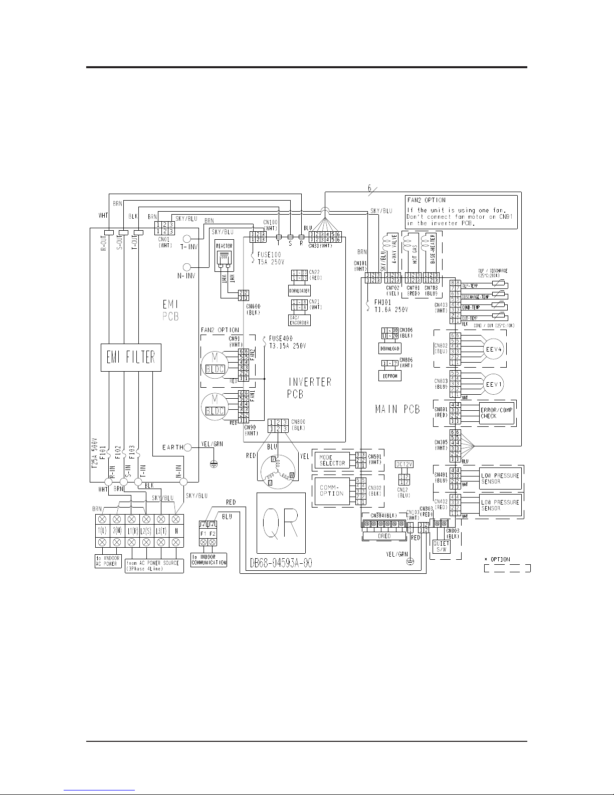
Wiring Diagram
Samsung Electronics 6-1
6. Wiring Diagram
6-1 Indoor Unit

Wiring Diagram
6-2 Samsung Electronics
6-2 Outdoor unit
QAC048KXQPCC / AC036KXQPCC / AC100KXADEH / AC036KXADEC
This Document can not be used without Samsung’s authorization.
Wiring Diagram
Samsung Electronics 6-3
QAC140KXADGH / AC048KXADGC
This Document can not be used without Samsung’s authorization.

Samsung Electronics 7-1
7. Reference Sheet
7-1 Index for Model Name
Model Code
+
P
+
P
+
C
+
MG
+
/
+
048
+
C
+
AC
+
K
+
N
Product Type
Code Type
AM
DVM
AJ PMA
AC CAC (USD) / ASD
AE EHS
AN VTL
AK
PAK (Packaged
System)
AG CHR
Product Type
Code Type
E 2012
F 2013
H 2014
J 2015
K 2016
L 2017
Product Type
Code Type
S Set (NASA)
N Indoor (NASA)
X Outdoor(NASA)
A Set ( NASA)
B
Indoor
( No NASA)
C
Outdoor
(No NASA)
Product Type (Indoor)
Code Type
1 1 WAY CST
2 2 WAY CST
N MINI 4 WAY CST
4 4 WAY CST
H
HSP DUCT
M
MSP DUCT
L LSP DUCT
E
FRESH AIR INTAKE
DUCT
G
CEILING CONCEILED
DUCT
C CEILING
J CONSOLE
F FLOOR MOUNTING
P FAC / PAC
Product Type (Outdoor)
Code Type
A
Inv+Side+General Temp
S Inv+Side+Low Temp
Q Inv+Side+Tropical Temp
F Inv+Top+Tropical Temp
B Non Inv+Side+General Temp
N Non Inv+Side+Low Temp
R Non Inv+Side+Tropical Temp
Z Non Inv+Top+Tropical Temp
1:1
(In/
out)
->4Way : 4 , MSP Duct :
M , Ceiling : C
Product Type (Indoor)
Code Type
F FLAGSHIP
P PREMIUM
D DELUXE
S STANDARD
Product Type (Outdoor)
Code Type
A
STANDARD+GENERAL
Temp.+MODULE
B
STANDARD+LOW
Temp.+MODULE
C
STANDARD+
TROPICAL+MODULE
D
STANDARD+GENERAL
Temp.+NON MODULE
S STANDARD
T DELUXE + TROPICAL
Capacity (3 DIGIT)
KW / BTU / Liter
Rating Voltage
Code Type
A A(115V, 60hz, 1Ф)
B B(220V, 60Hz, 1Ф)
C C(208~230V, 60Hz)
D D(200~220V, 50Hz)
E E(220~240V, 50Hz)
F F(208~230V, 60Hz, 3Ф)
G G(380~415V, 50Hz, 3Ф)
H H(380V, 60Hz, 3Ф)
J J(460V, 60Hz, 3Ф)
K K(220~240V, 50/60Hz, 1Ф)
M M(127V, 50Hz)
N N (380~415V, 50/60Hz, 3Ф)
Refrigerant
Code Type
Refrigerant
C
COOLING ONLY
R410a
H HEAT PUMP
R HEAT RECOVERY
D COOLING ONLY
R22
E HEAT PUMP
A Cooling only
R134
B Heat Pump
N N/A
ö
/ can be removed from the buyer card if there are not enough digits.
Buyer Name

7-2 Samsung Electronics
7-2 Refrigerating Cycle Diagram
QAC048KXQPCC
QAC036KXQPCC
Indoor unit
Heat Exchanger PFE 12mm, 2X63X785, 6-1PASS, FP1.5, Louver
Fan Motor BLDC, Sirocco, [C/H] 510/450/390 [rpm]
Outdoor unit
Heat Exchanger FMC 16mm, 1R*69S*910, 2EA, FP1.4, Corrugate
Fan Motor BLDC, Propeller, RPM MAX : 800 [rpm]
Indoor unit
Heat Exchanger PFE 12mm, 2X63X785, 6-1PASS, FP1.5, Louver
Fan Motor BLDC, Sirocco, [C/H] 430/390/370 [rpm]
Outdoor unit
Heat Exchanger PFC 16mm, 1R*69S*910, 2EA, FP1.4, Corrugate
Fan Motor BLDC, Propeller, RPM MAX : 800 [rpm]

Samsung Electronics 7-3
QAC140KXADGH
Indoor unit
Heat Exchanger PFE 12mm, 2X63X785, 6-1PASS, FP1.5, Louver
Fan Motor BLDC, Sirocco, [C/H] 490/430/390 [rpm]
Outdoor unit
Heat Exchanger F&T Φ7W, 2R*66S*950, FP1.7, Louver
Fan Motor BLDC, Propeller, RPM MAX : 800 [rpm]
QAC100KXADEH
Indoor unit
Heat Exchanger PFE 8mm, 2X63X785, 6-1PASS, FP1.5, Louver
Fan Motor BLDC, Sirocco, [C/H] 410/370/350 [rpm]
Outdoor unit
Heat Exchanger F&T Φ7W, 2R*46S*950, FP1.7, Louver
Fan Motor BLDC, Propeller, RPM MAX : 830 [rpm]

7-4 Samsung Electronics
QAC048KXADGC
Indoor unit
Heat Exchanger PFE 12mm, 2X63X785, 6-1PASS, FP1.5, Louver
Fan Motor BLDC, Sirocco, [C/H] 490/440/390 [rpm]
Outdoor unit
Heat Exchanger F&T Φ7W, 2R*66S*950, FP1.7, Louver
Fan Motor BLDC, Propeller, RPM MAX : 800 [rpm]
QAC036KXADGC
Indoor unit
Heat Exchanger PFE 12mm, 2X63X785, 6-1PASS, FP1.5, Louver
Fan Motor BLDC, Sirocco, [C/H] 410/370/350 [rpm]
Outdoor unit
Heat Exchanger F&T Φ7W, 2R*46S*950, FP1.7, Louver
Fan Motor BLDC, Propeller, RPM MAX : 830 [rpm]

This Service Manual is a property of Samsung Electronics Co., Ltd.
Any unauthorized use of Manual can be punished under applicable
International and/or domestic law.
© Samsung Electronics Co., Ltd. May. 2016.
Printed in Korea.
Code No. AC-00163E_1
*631*/2%$/6(59,&(3$571(51(7:25.
$UHD :HE6LWH
(XURSH&,60LGHDVW$IULFD JVSQVDPVXQJFVSRUWDOFRP
$VLD JVSQVDPVXQJFVSRUWDOFRP
1RUWK/DWLQ$PHULFD JVSQVDPVXQJFVSRUWDOFRP
&KLQD FKLQDVDPVXQJSRUWDOFRP
 Loading...